
Related Manuals for Microchip Technology ADM00902


Summary of Contents for Microchip Technology ADM00902
- Page 1 ADM00902 Demonstration Board for EMC2103 User’s Guide 2019 Microchip Technology Inc. DS50002905A...
- Page 2 Technology, and Symmcom are registered trademarks of Microchip Technology Inc. in other countries. GestIC is a registered trademark of Microchip Technology Germany II GmbH & Co. KG, a subsidiary of Microchip Technology Inc., in other countries. All other trademarks mentioned herein are property of their respective companies.
-
Page 3: Table Of Contents
Chapter 1. Product Overview ..................9 1.1 Introduction ..................... 9 1.2 EMC2103-4 Device Short Overview ............... 9 1.3 What is the ADM00902 Demonstration Board? ..........9 1.4 ADM00902 Demonstration Board Kit Contents ..........10 Chapter 2. Installation and Operation ................ 11 2.1 Introduction .................... - Page 4 ADM00902 Demonstration Board for EMC2103 User’s Guide A.6 Board – Top Silk ..................46 A.7 Board – Top Copper and Silk ............... 46 A.8 Board – Top Copper ..................47 A.9 Board – Bottom Copper ................47 A.10 Board – Bottom Copper and Silk ............... 48 A.11 Board –...
-
Page 5: Preface
Customer Support • Document Revision History DOCUMENT LAYOUT This document describes how to use the ADM00902 Demonstration Board for EMC2103 as a development tool to emulate and debug firmware on a target board. The manual layout is as follows: •... -
Page 6: Conventions Used In This Guide
ADM00902 Demonstration Board for EMC2103 User’s Guide CONVENTIONS USED IN THIS GUIDE This manual uses the following documentation conventions: DOCUMENTATION CONVENTIONS Description Represents Examples Arial font: ® Italic characters Referenced books MPLAB IDE User’s Guide Emphasized text ...is the only compiler... -
Page 7: Recommended Reading
Preface RECOMMENDED READING This user’s guide describes how to use the ADM00902 Demonstration Board for EMC2103. Other useful documents are listed below. The following Microchip document is available and recommended as a supplemental reference resource: EMC2103 Data Sheet – “RPM-Based Fan Controller with Hardware Thermal Shutdown”... - Page 8 ADM00902 Demonstration Board for EMC2103 User’s Guide NOTES: 2019 Microchip Technology Inc. DS50002905A-page 8...
-
Page 9: Chapter 1. Product Overview
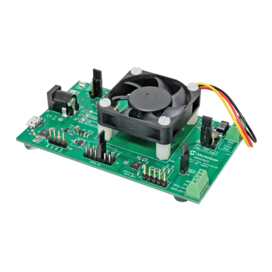
WHAT IS THE ADM00902 DEMONSTRATION BOARD? The ADM00902 Demonstration Board for EMC2103 provides an example of a fan control application using the EMC2103-4 fan controller. There is one fan channel, one internal temperature sensor and three remote temperature sensor inputs available. -
Page 10: Adm00902 Demonstration Board Kit Contents
ADM00902 Demonstration Board for EMC2103 User’s Guide ADM00902 DEMONSTRATION BOARD KIT CONTENTS The ADM00902 Demonstration Board kit includes the following: - One ADM00902 Demonstration Board for EMC2103 - Important Information Sheet - USB cable - Two NPN transistors in TO-92 package to be used as remote temperature diodes ... -
Page 11: Chapter 2. Installation And Operation
This section describes how to install the Microchip Thermal Management Utility GUI required in order to interact with the ADM00902 Demonstration Board. SYSTEM REQUIREMENTS The ADM00902 Demonstration Board is designed to be used with a personal computer ® ® (desktop or laptop) running Microsoft Windows 7 or later. - Page 12 ADM00902 Demonstration Board for EMC2103 User’s Guide FIGURE 2-2: Thermal Management Utility – License Agreement Window. Read and accept the License Agreement. Click the Next button to proceed. FIGURE 2-3: Thermal Management Utility – Installation Directory Window. Choose the desired installation directory and click Next.
- Page 13 Thermal Management Utility – Ready to Install Window. Once the installation directory has been chosen, click Next to begin the installation. FIGURE 2-5: Thermal Management Utility – Installing Window. Wait for the setup wizard to finish the installation. 2019 Microchip Technology Inc. DS50002905A-page 13...
- Page 14 ADM00902 Demonstration Board for EMC2103 User’s Guide FIGURE 2-6: Thermal Management Utility – Install Complete Window. Once the installation is complete, click Finish to exit the setup wizard. 2019 Microchip Technology Inc. DS50002905A-page 14...
-
Page 15: Chapter 3. Microchip Thermal Management Utility
EMC2103-4 device for temperature and fan control applications. FIRST LAUNCH The ADM00902 Demonstration Board for EMC2103 is required in order to start the Graphical User Interface. When the GUI is launched for the first time after the installation, or a new board is connected, it reads and displays the current settings of the fan driver. - Page 16 FIGURE 3-2: Thermal Management Utility Main Window.
-
Page 17: Control Toolbar
The loading process repopulates all the available fields and writes the settings into the connected ADM00902 Demonstration Board. This process takes up to 30 seconds to complete. 3.3.2... - Page 18 ADM00902 Demonstration Board for EMC2103 User’s Guide 3.3.4 Temperature Related Options The Temperature Related Options section is marked in Figure 3-3 with the number 4. The Heat Source Power Dissipation controls the on-board heat source connected to Channel 1 of the temperature sensor.
- Page 19 Note that the IC does not automatically determine the Min and Max values. This is done by software and is automated for the user’s convenience. FIGURE 3-4: Determine Fan Min/Max RPM Dialog Box. 2019 Microchip Technology Inc. DS50002905A-page 19...
- Page 20 ADM00902 Demonstration Board for EMC2103 User’s Guide 3.3.5.2 DEMO RPM OFFSET BUTTON The Demo RPM Offset button (marked as 5.2 in Figure 3-3) opens a dialog box (Figure 3-5) in which the Min RPM offset values can be configured. This relates only to the fan control algorithm implemented in software for the demo application example.
- Page 21 FIGURE 3-6: Advanced Settings Dialog Box. 3.3.5.4 UPDATE BUTTON The Update button (marked as 5.4 in Figure 3-3) refreshes the GUI fields with the values read from the chip. 2019 Microchip Technology Inc. DS50002905A-page 21...
-
Page 22: Demo Tab
ADM00902 Demonstration Board for EMC2103 User’s Guide DEMO TAB The Demo View section (Figure 3-7) consists of a Demo Options area (1) and a Temp/RPM Charts area (2). FIGURE 3-7: Demo View Section. 3.4.1 Demo Options This section provides control over the operating mode of the fan and its associated temperature source;... - Page 23 Advanced Settings menu (Figure 3-6). This outcome is dependent on the cooling solution (appropriate heat sink to dissipate the heat). FIGURE 3-9: Demo Options Fan – Auto Mode. 2019 Microchip Technology Inc. DS50002905A-page 23...
- Page 24 ADM00902 Demonstration Board for EMC2103 User’s Guide In Constant mode, the user can select only one temperature channel for monitoring and the fan speed will be adjusted as follows: • If the temperature is below the target temperature value, the fan is running at the minimum RPM value summed with the offset value.
- Page 25 For better visibility of the plotted values, a data table can be enabled from the chart’s context menu. The user must right-click the plot in order to trigger this menu and select the Both Graph and Table option, as displayed in Figure 3-13. FIGURE 3-13: Chart Options. 2019 Microchip Technology Inc. DS50002905A-page 25...
-
Page 26: Measurements Tab
ADM00902 Demonstration Board for EMC2103 User’s Guide MEASUREMENTS TAB This view contains all the values related to the temperature channels, fan parameters and status of the device features. FIGURE 3-14: Temperature Sensor View – Measurements Tab. The Measurements tab provides an overview of all the temperature, fan speed and state-related readings from the EMC2103-4 device: •... -
Page 27: Gpio Settings
ALERT pin indication of the GPIO status change (the on-board ALERT LED will turn on for every high-to-low or low-to-high transition detected on the GPIO pin). FIGURE 3-15: GPIO Settings. 2019 Microchip Technology Inc. DS50002905A-page 27... - Page 28 ADM00902 Demonstration Board for EMC2103 User’s Guide 3.6.2 Look-up Table In this section, the user can set up the configuration for the look-up table and set the parameters for the Drive and Temperature registers. FIGURE 3-16: Look-up Table. The Look-up Table Settings section (marked in...
- Page 29 Read. FIGURE 3-17: Registers List Tab. 3.6.4 Temperature Sensor Settings The Temperature Sensor Settings provides access to all of the sensor’s settings and limit configurations. FIGURE 3-18: Temperature Sensor. 2019 Microchip Technology Inc. DS50002905A-page 29...
- Page 30 ADM00902 Demonstration Board for EMC2103 User’s Guide Note that the TCRIT values can only be changed once after power-up. When starting the board with the SHDN_SEL jumper on a position that loads the settings from EEPROM (15k, 22k, 33k and open positions), this one-time TCRIT write operation will automatically be exhausted and the GUI will not update the values any more, nor be able to write other values to the EEPROM.
-
Page 31: Demo Exercises
Fan subtab and in the “Limit Settings (C)”, modify the Ext 1 “High” temperature to 45. 3. In the “ALERTS” section, in the “Mask individual settings”, check the corresponding box to “Ext 1”. 2019 Microchip Technology Inc. DS50002905A-page 31... - Page 32 ADM00902 Demonstration Board for EMC2103 User’s Guide 4. In the Demo tab, in the “Control and Plot Options” section, check the “Ext 1” box from the “Channel” column, and from the “Plot” column, check the boxes corresponding to “Ext 1” and “RPM”.
- Page 33 ALERT LED on the board turn on. When lowering the “Heat Source Power Dissipation” back to 80%, the LED will turn off after the temperature falls below the set target. The plot from the “Demo Data Acquisition” chart should look like the picture below. 2019 Microchip Technology Inc. DS50002905A-page 33...
- Page 34 ADM00902 Demonstration Board for EMC2103 User’s Guide 3.7.2 Look-up Table (LUT) Mode Example Steps: 1. From the taskbar, select the Load Settings button and load the configuration file named, ‘ADM00902_Default_Settings.bin’. 2. In the Demo tab, in the “Control and Plot Options”, check the “Ext 1” box from the “Channel”...
- Page 35 The Ext 1 temperature channel is used in this case as this is the channel that is affected by the on-board heat source. 4. From the taskbar, press the Start Acquisition button in order to start the demo. 2019 Microchip Technology Inc. DS50002905A-page 35...
- Page 36 ADM00902 Demonstration Board for EMC2103 User’s Guide 5. In the “Operating Mode” section, select from the drop-down menu, the LookUp Table option. 6. From the taskbar, set the “Heat Source Power Dissipation” to 80%. The fan speed will change to set to the defined RPM setting from the “LUT Config”...
-
Page 37: Chapter 4. Hardware Description
FOR EMC2103 USER’S GUIDE Chapter 4. Hardware Description ADM00902 DEMONSTRATION BOARD FOR EMC2103 DESCRIPTION The ADM00902 Demonstration Board for EMC2103 becomes fully functional when it is powered through the USB connector and the 12V BOOST for the V supply is selected. - Page 38 ADM00902 Demonstration Board for EMC2103 User’s Guide 4.1.1 Power Selection The fan and heat source power input (V ) is selectable through a 3-way jumper assembly comprised of J3 and J4 with the following options: • 5V USB (direct 5V option for 5V fans) •...
- Page 39 Note that by setting the PWM duty cycle at 50%, the fan RPM won’t be set at 50%. This is where the EMC2103-4 RPM-based Fan Speed Control Algorithm solves the problem, by automatically adjusting the PWM duty cycle to achieve a target RPM. 2019 Microchip Technology Inc. DS50002905A-page 39...
- Page 40 ADM00902 Demonstration Board for EMC2103 User’s Guide 4.1.4 On-Board Demonstration Heat Source and Remote Diode The Q1 dual NPN transistor is used both as a heat source and as a remote diode, in order to help provide an out-of-the-box demonstration of the implemented PID (proportional-integral-derivative) controller in the Thermal Management Utility GUI.
-
Page 41: Appendix A. Schematic And Layouts
ADM00902 DEMONSTRATION BOARD FOR EMC2103 USER’S GUIDE Appendix A. Schematic and Layouts INTRODUCTION This appendix contains the following schematics and layouts for the ADM00902 Demonstration Board for EMC2103: • Board – Schematic – EMC2103-4 • Board – Schematic – Fan Drive •... -
Page 42: Board - Schematic - Emc2103-4
BOARD – SCHEMATIC – EMC2103-4 +3.3V +12V_Boost +VFan +12V_Ext 2200 pF +3.3V 0.1 μF 0603 50V 0603 +5V_USB +3.3V +3.3V +3.3V VFan Power Selector ALERT DP2/DN3 SYS_SHDN 6.8k 2200 pF +VFan 0603 0603 0603 GPIO2 50V 0603 GPIO2 DP2/DN3 +VFan 6.8k 0603 ALERT... -
Page 43: Board - Schematic - Fan Drive
BOARD – SCHEMATIC – FAN DRIVE +VFan +VFan +3.3V 0.1 μF 0603 10 μF 1206 MCP1401 0603 PWM_FAN PWM_DRV DMP3099 0603 PWM_FAN V_DRV TACH 68 μH TERMINAL 1x4 MBR230LSFT1G 47 μF... -
Page 44: Board - Schematic - Interface And Power
BOARD – SCHEMATIC – INTERFACE AND POWER MCP1703A/3.3V +12V_Ext +12V +12V_Ext +3.3V TP TAB Silver TP TAB Silver +5V_USB 220R 2.1mm 4.7 μF 0.17 μF 0.1 μF 4.7 μF BAT54C 0805 0603 0603 0805 +12V_Ext + 5V_USB +3.3V +VFan USB_N USB_P 0603 0603... -
Page 45: Board - Schematic - Mechanical
Nut M3 Nylon Nut M3 Nylon Nut M3 Nylon RUBBER PAD D9.4 H4.8 CBL1 Shunt 2.54 mm 1x2 Handle USB Male-A to Male Micro-B FAN1 FAN 40x10 mm 3-Wire 2N3904TA 2N3904TA MECH MECH 2019 Microchip Technology Inc. DS50002905A-page 45... -
Page 46: Board - Top Silk
ADM00902 Demonstration Board for EMC2103 User’s Guide BOARD – TOP SILK BOARD – TOP COPPER AND SILK 2019 Microchip Technology Inc. DS50002905A-page 46... -
Page 47: Board - Top Copper
Schematic and Layouts BOARD – TOP COPPER BOARD – BOTTOM COPPER 2019 Microchip Technology Inc. DS50002905A-page 47... -
Page 48: A.10 Board - Bottom Copper And Silk
ADM00902 Demonstration Board for EMC2103 User’s Guide A.10 BOARD – BOTTOM COPPER AND SILK A.11 BOARD – BOTTOM SILK 2019 Microchip Technology Inc. DS50002905A-page 48... -
Page 49: Appendix B. Bill Of Materials (Bom)
ADM00902 DEMONSTRATION BOARD FOR EMC2103 USER’S GUIDE Appendix B. Bill of Materials (BOM) ADM00902 DEMONSTRATION BOARD FOR EMC2103 – BILL OF MATERIALS (BOM) TABLE B-1: ADM00902 DEMONSTRATION BOARD FOR EMC2103 – BILL OF MATERIALS (BOM) Qty. Reference Description Manufacturer Part Number Ceramic Capacitor, 0.1 F, 25V, 10%,... - Page 50 ADM00902 Demonstration Board for EMC2103 User’s Guide TABLE B-1: ADM00902 DEMONSTRATION BOARD FOR EMC2103 – BILL OF MATERIALS (BOM) (CONTINUED) Qty. Reference Description Manufacturer Part Number Connector Header-2.54, Male, 1x1, Samtec, Inc. TSW-101-07-S-S Gold, 5.84 MH, Through-Hole, Vertical Connector Header-2.54, Male, 1x4,...
- Page 51 Bill of Materials (BOM) TABLE B-1: ADM00902 DEMONSTRATION BOARD FOR EMC2103 – BILL OF MATERIALS (BOM) (CONTINUED) Qty. Reference Description Manufacturer Part Number Resistor, Thick Film, 30 k 1%, Stackpole RMCF0603FT30K0 1/10W, Surface Mount, 0603 Electronics, Inc. ® R4, R12, R20, Resistor, Thick Film, 10 k...
- Page 52 ADM00902 Demonstration Board for EMC2103 User’s Guide TABLE B-2: BILL OF MATERIALS – MECHANICAL PARTS Qty. Reference Description Manufacturer Part Number CBL1 Mechanical Headers & Wires Cable, USB DongGuan A006ZX027 Male-A to Male Micro-B, Clear, 4 ZhanXin ® FAN1 Mechanical Headers & Wires Fan, 12V, DC,...
- Page 53 Bill of Materials (BOM) NOTES: 2019 Microchip Technology Inc. DS50002905A-page 53...
-
Page 54: Worldwide Sales And Service
New York, NY Tel: 46-31-704-60-40 Tel: 631-435-6000 Sweden - Stockholm San Jose, CA Tel: 46-8-5090-4654 Tel: 408-735-9110 UK - Wokingham Tel: 408-436-4270 Tel: 44-118-921-5800 Canada - Toronto Fax: 44-118-921-5820 Tel: 905-695-1980 Fax: 905-695-2078 2019 Microchip Technology Inc. DS50002905A-page 54 05/14/19...
Need help?
Do you have a question about the ADM00902 and is the answer not in the manual?
Questions and answers