Table of Contents
Advertisement
Quick Links
ATtiny817 Xplained Mini
ATtiny817 Xplained Mini
Preface
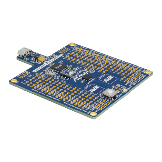
The ATtiny817 Xplained Mini evaluation kit is a hardware platform to evaluate the ATtiny817 microcontroller.
®
Supported by the Atmel Studio and MPLAB
X integrated development platform, the kit provides easy access to the
features of the ATtiny817 and explains how to integrate the device into a custom design.
The Xplained Mini series evaluation kits include an on-board mini embedded debugger. No external tools are
necessary to program the ATtiny817.
User Guide
DS50002657B-page 1
©
2019 Microchip Technology Inc.
Advertisement
Table of Contents

Related Manuals for Microchip Technology ATtiny817 Xplained Mini


Summary of Contents for Microchip Technology ATtiny817 Xplained Mini
-
Page 1: Preface
ATtiny817 Xplained Mini ATtiny817 Xplained Mini Preface The ATtiny817 Xplained Mini evaluation kit is a hardware platform to evaluate the ATtiny817 microcontroller. ® Supported by the Atmel Studio and MPLAB X integrated development platform, the kit provides easy access to the features of the ATtiny817 and explains how to integrate the device into a custom design. -
Page 2: Table Of Contents
ATtiny817 Xplained Mini Table of Contents Preface................................1 Introduction............................. 3 1.1. Features............................3 1.2. Kit Overview..........................3 Getting Started............................5 2.1. Xplained Mini Quick Start......................5 2.2. Design Documentation and Relevant Links................. 5 Xplained Mini............................6 3.1. Mini Embedded Debugger......................6 3.2. -
Page 3: Introduction
– 5.0V from USB – 3.3V regulator – External voltage • Arduino Shield Compatible Footprints Kit Overview The ATtiny817 Xplained Mini evaluation kit is a hardware platform to evaluate the ATtiny817. User Guide DS50002657B-page 3 © 2019 Microchip Technology Inc. - Page 4 ATtiny817 Xplained Mini Introduction Figure 1-1. ATtiny817 Xplained Mini Evaluation Kit Overview Power CDC UART Power source Status Micro USB Target power mEDBG Ground (J105) (J102) Con nector (J100) (ATmega32U4) Target I/O Shared I/Os Disconnected with N.M. 0-Ohm Digital I/O High (J201)
-
Page 5: Getting Started
The ATtiny817 device is programmed and debugged by the on-board Mini Embedded Debugger and, therefore, no external programmer or debugger tool is required. Design Documentation and Relevant Links The following list contains links to the most relevant documents and software for the ATtiny817 Xplained Mini. • Xplained Products - Xplained Evaluation Kits are a series of easy-to-use evaluation kits for Microchip microcontrollers and other Microchip products. -
Page 6: Xplained Mini
The mEDBG controls one status LED on the ATtiny817 Xplained Mini. The table below shows how the LED is controlled in different operation modes. -
Page 7: Medbg Configuration
ATtiny817 Xplained Mini Xplained Mini Figure 3-1. External Clock Footprint The mEDBG CPU clock frequency depends on the selected voltage, see the table below. Table 3-2. CPU Clock vs. Voltage Target Voltage mEDBG CPU Clock 3.3V 8 MHz 5.0V 16 MHz mEDBG Configuration The operation of the mEDBG can be configured by writing registers in the mEDBG. - Page 8 ATtiny817 Xplained Mini Xplained Mini Info: The fuse filter prevents users from changing critical fuses using Atmel Studio. However, it does not prevent users from setting fuses freely using the command line interface atprogram bundled with Atmel Studio. User Guide DS50002657B-page 8 ©...
-
Page 9: Medbg Firmware Upgrade And Manual Bootloader Entry
The mEDBG firmware is updated through the programming dialog in Atmel Studio. If you are unable to upgrade the mEDBG firmware on your ATtiny817 Xplained Mini, you can try the command line utility atfw.exe provided with the Atmel Studio. atfw.exe is located in the atbackend folder in your Atmel Studio install location. -
Page 10: Hardware User Guide
The following sections describe the implementation of the relevant peripherals, headers, and connectors on ATtiny817 Xplained Mini and their connection to the ATtiny817. The tables of connections in the sections also describe which signals are shared between the headers and on-board functionality. - Page 11 ATtiny817 Xplained Mini Hardware User Guide Figure 4-1. ATtiny817 Xplained Mini Assembly Drawing User Guide DS50002657B-page 11 © 2019 Microchip Technology Inc.
-
Page 12: Power Sources
Power Sources The ATtiny817 Xplained Mini kit can be powered by a USB or an external voltage input VIN. The default power source is 5.0V from a USB. The USB port is protected with a 500 mA PTC resettable fuse. - Page 13 ATtiny817 Xplained Mini Hardware User Guide Table 4-2. J201 Digital I/O High Header J201 ATtiny817 Pin Arduino Numbering Functions Comment TCA_W5 Not connected by default. Can be connected by adding a 0Ω resistor to R204. Shared with J200, J203, and user button.
- Page 14 ATtiny817 Xplained Mini Hardware User Guide ...continued J203 ATtiny817 Pin Arduino Numbering Functions Comment External voltage input Table 4-5. J204 Analog I/O Header J204 ATtiny817 Pin Arduino Numbering Functions Comment AIN04 AIN05 AIN06 Shared with QTouch Button 1 AIN07 Shared with...
-
Page 15: Current Measurement
ATtiny817 Xplained Mini Hardware User Guide ...continued Signal Name Signal Description ADC(-) Analog-to-Digital converter, alternatively negative part of differential ADC GPIO1 General purpose I/O GPIO2 General purpose I/O PWM(+) Pulse-Width Modulation, alternatively positive part of differential PWM PWM(-) Pulse-Width Modulation, alternatively negative part of differential PWM... -
Page 16: Disconnecting Medbg
ATtiny817 Xplained Mini Hardware User Guide Figure 4-4. Current Measurement VCC_BOARD VCC_TARGET Remove 0-Ohm res istor Disconnecting mEDBG The target controller ATtiny817 can be completely separated from the mEDBG, but this requires some small modifications to the board using a soldering iron. By removing the resistors in the sections shown in the figure below, the mEDBG is completely disconnected from the target controller. -
Page 17: Peripherals
PB3 UART RX Peripherals 4.5.1 There is one yellow LED available on the ATtiny817 Xplained Mini board that can be turned ON and OFF. The LED can be activated by driving the connected I/O line to VCC. Table 4-8. LED Connection... -
Page 18: Embedded Debugger Implementation
Hardware User Guide Embedded Debugger Implementation ATtiny817 Xplained Mini contains a Mini Embedded Debugger (mEDBG) that can be used to program the ATtiny817 using Unified Program and Debug Interface (UPDI). The mEDBG also includes a Virtual Com port interface over UART. -
Page 19: Hardware Revision History And Known Issues
"nnnnrrssssssssss" n = product identifier r = revision s = serial number The product identifier for ATtiny817 Xplained Mini is A09-2658. Revision 6 Revision 6 is identical to revision 5 and revision 4 with increased test coverage. Revision 5 Revision 5 is identical to revision 4 with increased test coverage. -
Page 20: Document Revision History
ATtiny817 Xplained Mini Document Revision History Document Revision History Doc. Rev Date Comment 12/2019 Removed the section covering the mEDBG command line interface as it was obsolete. 08/2017 Converted to Microchip format and replaced the Atmel document number 42726A. Added links to QTouch example application in 4.5.3 QTouch... -
Page 21: The Microchip Website
ATtiny817 Xplained Mini The Microchip Website Microchip provides online support via our website at http://www.microchip.com/. This website is used to make files and information easily available to customers. Some of the content available includes: • Product Support – Data sheets and errata, application notes and sample programs, design resources, user’s guides and hardware support documents, latest software releases and archived software •... -
Page 22: Trademarks
The Adaptec logo, Frequency on Demand, Silicon Storage Technology, and Symmcom are registered trademarks of Microchip Technology Inc. in other countries. GestIC is a registered trademark of Microchip Technology Germany II GmbH & Co. KG, a subsidiary of Microchip Technology Inc., in other countries. -
Page 23: Worldwide Sales And Service
New York, NY Tel: 46-31-704-60-40 Tel: 631-435-6000 Sweden - Stockholm San Jose, CA Tel: 46-8-5090-4654 Tel: 408-735-9110 UK - Wokingham Tel: 408-436-4270 Tel: 44-118-921-5800 Canada - Toronto Fax: 44-118-921-5820 Tel: 905-695-1980 Fax: 905-695-2078 User Guide DS50002657B-page 23 © 2019 Microchip Technology Inc.
Need help?
Do you have a question about the ATtiny817 Xplained Mini and is the answer not in the manual?
Questions and answers