Table of Contents
Advertisement
Quick Links
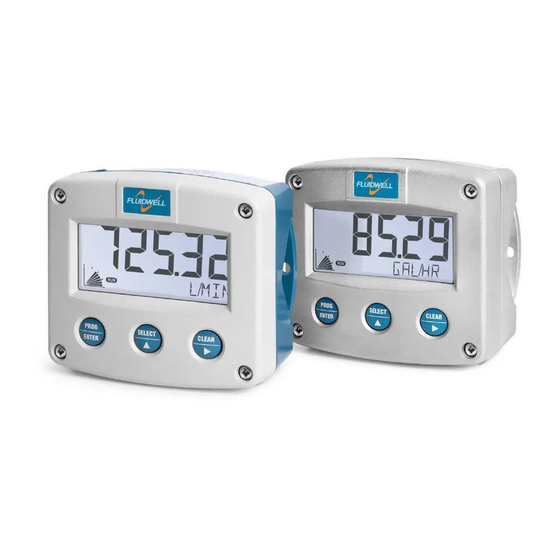
F133-P
Delivery controller / Dispenser
with pump start and valve control
Signal input flowmeter: pulse, Namur and coil.
Status inputs: start and stop.
Control outputs: two pump / valve control outputs.
Options: Intrinsically Safe, Modbus communication and backlight.
F-Series - Field mounted indicators for safe and hazardous areas.
More info: www.fluidwell.com/fseries
Advertisement
Table of Contents

Related Manuals for Fluidwell F133-P


Summary of Contents for Fluidwell F133-P
- Page 1 Signal input flowmeter: pulse, Namur and coil. Status inputs: start and stop. Control outputs: two pump / valve control outputs. Options: Intrinsically Safe, Modbus communication and backlight. F-Series - Field mounted indicators for safe and hazardous areas. More info: www.fluidwell.com/fseries...
- Page 2 Page 2 FW_F133P_v1702_02_EN...
-
Page 3: Safety Instructions
This unit must be installed in accordance with the EMC guidelines (Electro Magnetic Compatibility). Do connect a proper grounding to the metal enclosure as indicated if the F133-P has an incoming power line which carries a 115-230V AC. The Protective Earth (PE) wire may never be disconnected or removed. -
Page 4: About The Manual
This manual describes the standard unit as well as most of the options available. For additional information, please contact your supplier. A hazardous situation may occur if the F133-P is not used for the purpose it was designed for or is used incorrectly. Please carefully note the information in this operating manual indicated by the pictograms: A "warning !"... -
Page 5: Table Of Contents
Operator information and functions ................7 2.4. dispenser functional diagram ..................9 Configuration........................10 3.1. How to program the F133-P ..................10 3.1.1. Setup menu - Settings ....................12 3.1.2. Explanation of Setup menu 1 - Total ................. 13 3.1.3. -
Page 6: Introduction
Fig. 1: Typical application Configuration of the unit The F133-P is designed for use in many types of applications. For that reason, a setup menu is available to program the F133-P according to your specific requirements. The setup includes several important features, such as K-Factors, engineering units, signal selection, power management (to extend battery life-time), etc. -
Page 7: Operational
Take careful notice of the "Safety rules, instructions and precautionary measures" in the front of this manual. This chapter describes the daily use of the F133-P . This instruction is meant for users / operators. 2.2. CONTROL PANEL The control panel has three keys. The available keys are: Fig. - Page 8 "LO RATE" or "HI RATE". If pause is enabled, the delivery can be restarted. Maximum batch: When the total quantity delivered exceeds a certain quantity, the F133-P will switch-off all relays and generate an "MAX BATCH" alarm. If pause is enabled, the delivery can be restarted. ...
-
Page 9: Dispenser Functional Diagram
Page 9 2.4. DISPENSER FUNCTIONAL DIAGRAM The function of the F133-P depends on the different settings in the setup menu. The example is given for a typical configuration. START THE DELIVERY PAUSE / STOP THE DELIVERY (pause is enabled) STOP THE DELIVERY (overrun timer is set) LEGEND Idle, waits for new delivery. -
Page 10: Configuration
How to enter the setup menu When the setup menu is protected by a password, the F133-P asks for a password to access the setup menu. When in the operator mode, press and hold the PROG/ENTER key for 7 seconds to access the setup menu. - Page 11 The START/▲ key and the STOP/► key are used for navigation. The explanation assumes that you are in the submenu PRESET. When you are: in the first setting and you navigate to the previous setting, the F133-P goes back to the related main menu.
-
Page 12: Setup Menu - Settings
1 - 247 mode bus-rtu; bus-asc; off databits 7 bits; 8 bits parity odd; even; none comm. lock disable; time-out; full OTHERS model F133-P software version nn:nn:nn serial no. nnnnnnn password 0000 - 9999 tag-nr 0000000 - 9999999 FW_F133P_v1702_02_EN... -
Page 13: Explanation Of Setup Menu 1 - Total
Page 13 3.1.2. EXPLANATION OF SETUP MENU 1 - TOTAL This setting is used to select the engineering unit for the indication of the batch UNIT total and the accumulated total. When you change the engineering unit, you must recalculate and reprogram the K-factor for the (accumulated) total. -
Page 14: Explanation Of Setup Menu 3 - Display
The backlight brightness can be adjusted from 0% (off) to 100% (full brightness) in steps of 20%. When the F133-P is only loop powered, the backlight is disabled. An external power supply is required to supply the backlight. This setting is used to set the behavior of the backlight (bl) during an alarm BL ALARM condition. -
Page 15: Explanation Of Setup Menu 5 - Flowmeter
As soon as the unit is full operational, the flow can be monitored. The F133-P will switch-off relay 1 and 2 (or relay 2 only: see setting 65/66) as soon as during X-seconds no pulses have been received from the flowmeter. -
Page 16: Explanation Of Setup Menu 7 - Status
0.0 seconds, this function is disabled. 3.1.7. EXPLANATION OF SETUP MENU 7 - STATUS For external control of the F133-P, the unit can be started and/or stopped with two external switches. STATUS INPUT 1 Following functions can be selected: OFF: status input is disabled. -
Page 17: Explanation Of Setup Menu 9 - Others
Page 17 3.1.9. EXPLANATION OF SETUP MENU 9 - OTHERS For support and maintenance it is important to have information about the characteristics of the F133-P. Your supplier will ask for this information when support is required. MODEL This setting shows the model name. -
Page 18: Dimensions- Enclosure
Page 18 4.3. DIMENSIONS- ENCLOSURE 75 mm (2.95") 112 mm (4.40") 130 mm (5.12") 12mm 12mm 30mm 30mm 24mm 24mm M20 x 1,5 6 x M12 36mm 36mm 25mm 25mm 1/2"NPT 1/2"NPT 1/2"NPT 30mm 30mm 0.12" 0.12" M16 x 1,5 M16 x 1,5 3x 1/2"NPT M20 x 1,5... - Page 19 Page 19 GRP enclosures: 75 mm (2.95") 112 mm (4.40") 130 mm (5.12") HK back box: (flat bottom) 75 mm (2.95") 118 mm (4.65”) 25mm 25mm D=20mm D=20mm 12mm 12mm 30mm 30mm 24mm 24mm D=12mm D=16mm D=16mm D=20mm 36mm 36mm 0.12”...
-
Page 20: Installing The Hardware
4.4.1. GENERAL INSTALLATION GUIDELINES In the F133-P , different types of bonding and earthing are used. The common (ground) is mostly used for termination of the wire shields and the Protective Earth (PE) is used for electrical safety. The F133-P that came with a power module type PM; 110V-230V AC or type PD/PF with an option OR (the relays can handle 110V-230V AC) shall be connected to the Protective Earth (PE) stud which is installed in the metal back panel. -
Page 21: Aluminum Enclosure - Field Mounted
Do not use the terminal 00 to connect the protective earth wire, the 00 and the common ground terminals are internally connected. Be careful, to prevent damage to equipment when you connect different power supplies (sensor, PLC, etc.). Inside the Fluidwell display, the common grounds are internally connected to each other. -
Page 22: Plastic (Grp) Enclosure
Page 22 4.4.4. PLASTIC (GRP) ENCLOSURE The PE connection The F133-P in a GRP enclosure meets the requirements of class 2 (double insulated). Therefore the incoming PE wire is terminated with an insulating end cap. Type PM (110-230V AC) Type PD-OR / PF-OR (8-24V AC) -
Page 23: Terminal Connectors
Page 23 4.4.3. TERMINAL CONNECTORS Refer to Appendix A: Technical Specification Fig. 9: Overview of terminal connectors - Standard configuration and options SENSOR SUPPLY For type PB/PC; PX; AP: There is no real sensor supply out available. Only a limited power supply is available. - Page 24 5. Close the F133-P . Risk of electrocution - High voltage! Make sure, all the leads to the terminals are disconnected from the F133-P and NEVER connect the mains power supply to the unit when the protection cover has been removed!
- Page 25 Page 25 Option OT: A passive transistor output is available with this option. Max. driving capacity 300mA@50V DC. Fig. 11: Terminal connections - Passive transistor output (typical) Option OA: An active 24V DC signal according to the functions R1 and R2 is available with this option. Max.
- Page 26 Fig. 14: Terminal connections - Coil signal input (typical) Pulse-signal NPN / NPN-LP: The F133-P is suitable for use with flowmeters which have a NPN output signal. For reliable pulse detection, the pulse amplitude has to go below 1.2V. Signal setting NPN-LP employs a low-pass signal noise filter, which limits the maximum input frequency (read chapter 3).
- Page 27 Pulse-signal PNP / PNP-LP: The F133-P is suitable for use with flowmeters which have a PNP output signal. 3V is offered on terminal 11 which has to be switched by the sensor to terminal 10 (SIGNAL). For a reliable pulse detection, the pulse amplitude has to go above 1.2V.
- Page 28 Page 28 NAMUR-signal: The F133-P is suitable for flowmeters with an Namur signal. The standard F133-P is not able to power the Namur sensor, as an external power supply for the sensor is required. However, a 8.2V sensor supply voltage (terminal 11) can be provided with power supply type PD, PF, PM.
- Page 29 Page 29 Terminal 26-31: type CB / CH / CI / CT - communication RS232 / RS485 / TTL (option) For connections, refer to figure: Overview of terminal connectors - Standard configuration and options Full serial communications and computer control in accordance with RS232 (length of cable max. 15 meters) or RS485 (length of cable max.
-
Page 30: Intrinsically Safe Applications
KEMA 03ATEX1071 U or IECEx KEM 08.0005U is allowed in Hazardous Area. Read chapter 6 for battery replacement instructions. When the enclosure of the F133-P is made of aluminum alloy, when used in a potentially explosive atmosphere requiring apparatus of EPL Ga, the indicator shall be installed so, that even in the event of rare incidents, an ignition source due to impact or friction sparks between the enclosure and iron/steel is excluded. -
Page 31: Terminal Connectors Intrinsically Safe Applications
Page 31 Label information pulse input type – F1xx-..-..-XI (inside and outside the enclosure) Fig. 23: Label information - Intrinsically safe application (typical) 5.2. TERMINAL CONNECTORS INTRINSICALLY SAFE APPLICATIONS The unit is classified as group IIB/IIIC by default. Classification of the unit as group IIC is only possible under the following conditions: The indicator is either supplied by ... - Page 32 5. Close the F133-P. Risk of electrocution - High voltage! Make sure, all the leads to the terminals are disconnected from the F133-P and NEVER connect the mains power supply to the unit when the protection cover has been removed! Type PD-XI Power supply in: 16-30V DC / max.
-
Page 33: Configuration Examples Intrinsically Safe Applications
Page 33 5.3. CONFIGURATION EXAMPLES INTRINSICALLY SAFE APPLICATIONS Fig. 26: F133-P-(CT)-OT-PC-(PX)-XI - Battery powered - IIB/IIC – IIIC Fig. 27: F133-P-(CT)-OT-(PX)-XI - Basic power supply - IIB/IIC – IIIC FW_F133P_v1702_02_EN... - Page 34 Page 34 Fig. 28: F133-P-(CT)-OT-PD-XI - External power supply - IIB/IIC – IIIC Fig. 29: F133-P-CT-OT-PX-XI - Basic power supply - IIB/IIC – IIIC FW_F133P_v1702_02_EN...
-
Page 35: Battery Replacement Instructions
Page 35 BATTERY REPLACEMENT INSTRUCTIONS 5.4.1. SAFETY INSTRUCTIONS Handle the battery with care. A mistreated battery can become unsafe. Unsafe batteries can cause (serious) injury to persons. Only use batteries which are certified for use in hazardous areas. The use of standard batteries in hazardous area's is not safe and prohibited. -
Page 36: Maintenance
Repairs should only be carried out by the manufacturer or his authorized agent. 6.3. REPAIR POLICY I you have any problem with your Fluidwell product and you wish to repair it, please follow the procedure below: a. Obtain a Return Material Authorization (RMA) from your supplier or distributor Together with the RMA, you need to complete a repair form to submit detailed information about the problem. -
Page 37: Appendix A: Technical Specification
Page 37 APPENDIX A: TECHNICAL SPECIFICATION GENERAL Display Type High intensity reflective numeric and alphanumeric LCD, UV-resistant. Digits Seven 17mm (0.67") and eleven 8mm (0.31"). Various symbols and measuring units. Refresh rate User definable: 8 times/sec - 30 secs. Type ZB LCD with LED backlight. - Page 38 Page 38 Sensor excitation Type PB / PC / PX 3V DC for low power pulse signals and 1.2V DC for coil pick-up. Type PD 1.2; 3; 8.2; 12; 24V DC - max. 50mA@24V DC Type PD-XI Intrinsically safe: Pulse signals: 1.2; 3; 8.2 - max. 7mA@8.2V DC. Type PF / PM 1.2;...
- Page 39 Page 39 OPERATIONAL Operator functions Functions start / interrupt and stop the delivery, total can be reset to zero. Shown information delivered total flow rate accumulated delivered total (7 digits) number of delivies executed ...
-
Page 40: Appendix B: Problem Solving
Page 40 APPENDIX B: PROBLEM SOLVING In this appendix, several problems are included that can occur when the F133-P is going to be installed or while it is in operation. Flowmeter does not generate pulses: Check: Signal selection; ... -
Page 41: Appendix C: Communication Variables
Although most Modbus Masters will support variables that span 2 registers, variables spanning more registers sometimes require you to manually calculate the resulting value. For additional information regarding using your Fluidwell Modbus device, please read the ‘Fluidwell General Modbus Communication Protocol’ and ‘Modbus troubleshooting guide’ that are available through our website or your distributor. - Page 42 Page 42 SETUP VARIABLES OF THE F133-P REGISTER TYPE VALUE / REMARKS VARIABLE ADDRESS TOTAL REGISTERS [d] 32 40033 unit uint16 0=none 3=kg 6= USGAL [h] 0x020 4= lb 7=bbl 2= m 5=GAL [d] 33 40034 decimals uint16 0…3 [h] 0x021...
- Page 43 2=test 7=pause 130=alarm hi 3=delay 8=stop 131=dispense 4=begin 9=finish 1=3=max error 132=error [d] 57 40058 batch action Uint16 0=none 2= n/a 4=finish [h] 0x09D 1=n/a 3= n/a Do write finish to the unit to release the F133-P according setup FW_F133P_v1702_02_EN...
-
Page 44: Appendix D: Declaration Of Conformity
Page 44 APPENDIX D: DECLARATION OF CONFORMITY FW_F133P_v1702_02_EN... -
Page 45: Index Of This Manual
Page 45 INDEX OF THIS MANUAL accumulated Total Intrinsically Safe options active output IP classification actual settings maintenance backlight model density NAMUR-signal batch counter 9, 14 no-pulse time batch total 9, 14 operational 8, 11, 12, 18, 37 battery life time operator level begin time overrun time... -
Page 46: List Of Figures In This Manual
Fig. 25: Switch position voltage selection option PD-XI ..............32 Fig. 26: F133-P-(CT)-OT-PC-(PX)-XI - Battery powered - IIB/IIC – IIIC ..........33 Fig. 27: F133-P-(CT)-OT-(PX)-XI - Basic power supply - IIB/IIC – IIIC ..........33 Fig. 28: F133-P-(CT)-OT-PD-XI - External power supply - IIB/IIC – IIIC ..........34 Fig. - Page 47 8 – COMM modB 81 speed 9600 82 address 83 mode BUS-RTU 84 databits 85 parity none 86 comm.lock disabled 8 - OTHERS 81 model F133-P F133-P F133-P 82 software version 03.03.xx 83 serial number xxxxxxxx 84 Password 0000 85 Tag-nr. 0000000 FW_F133P_v1702_02_EN...
- Page 48 Page 48 Fluidwell B.V. FW_F133P_v1702_02_EN PO box 6 Voltaweg 23 Website: www.fluidwell.com 5460 AA Veghel 5466 AZ Veghel Find your nearest representative: www.fluidwell.com/representatives the Netherlands the Netherlands © 2017 Fluidwell B.V.: FW_F133P_v1702_02_EN...
Need help?
Do you have a question about the F133-P and is the answer not in the manual?
Questions and answers