Table of Contents
Advertisement
Quick Links
RESISTRON
RES-430
Operating
Instructions
Important features
•
Microprocessor technology
•
LC display (green), 4 lines, 20 characters (multilingual)
•
Automatic zero calibration (AUTOCAL)
•
Automatic optimization (AUTOTUNE)
•
Automatic frequency adjustment
•
Secondary control
•
Heatsealing band alloy and temperature range selectable
•
Time control, heatsealing time and cooling time settable
•
Configurable relay output, e.g. "end of cycle"
•
Time or temperature-controlled cooling phase
•
0...10VDC analog output for ACTUAL temperature
•
Load cell interface for monitoring closing pressure
•
Serial data interface (optional)
•
Fault diagnosis
Industrie-Elektronik GmbH
Gansäcker 21
D-74321-Bietigheim-Bissingen (Germany)
GB
Tel: +49/(0)7142/7776-0
Fax: +49/(0)7142/7776-19
E-mail:
info@ropex.de
Internet:
www.ropex.de
Data subject to change
Advertisement
Table of Contents

Related Manuals for Ropex Resistron RES-430 Series


Summary of Contents for Ropex Resistron RES-430 Series
- Page 1 0…10VDC analog output for ACTUAL temperature • Load cell interface for monitoring closing pressure • Serial data interface (optional) • Fault diagnosis Industrie-Elektronik GmbH Tel: +49/(0)7142/7776-0 E-mail: info@ropex.de Gansäcker 21 Fax: +49/(0)7142/7776-19 Internet: www.ropex.de D-74321-Bietigheim-Bissingen (Germany) Data subject to change...
-
Page 2: Table Of Contents
Wiring diagram with solenoid drive 11.1 Ropex settings ....46 (optional) ..... . 15 11.2 Customer settings . -
Page 3: Safety And Warning Notes
Heatsealing band Line filter A basic prerequisite for reliable and safe operation of The use of an original ROPEX line filter is mandatory in the system is the use of suitable heatsealing bands. order to comply with the standards and provisions mentioned in section 1.6 "Standards / CE marking"... -
Page 4: Standards / Ce Marking
ROPEX are used. If not, then devices that have been modified, relabeled or the equipment is operated on the user's own otherwise altered by the customer, for example in an responsibility. -
Page 5: Principle Of Operation
Principle of operation Principle of operation The resistance of the heatsealing band, which is PLEASE NOTE! temperature-sensitive, is monitored 50x per second RESISTRON temperature controllers play a significant (60x at 60Hz) by measuring the current and voltage. role in enhancing the performance of modern The temperature calculated with the help of these machines. -
Page 6: Modifications (Mods)
Modifications (MODs) / optical data interface the plug-in connections make this controller easy to install. Modifications (MODs) / optical data interface Modifications Optional data interface (piggyback module) No modifications are available for the RESISTRON temperature controller RES-430. A serial data interface (piggyback module) is optionally available for the RES-430 controller. - Page 7 Modifications (MODs) / optical data interface 5.2.1 Scope of supply / installation The serial piggyback module is supplied with spacers for installation on the motherboard of the RES-430. Proceed as follows to install the module. Sub-D connector, 9-pole 4x spacer for serial Piggyback module Snap-on...
-
Page 8: Technical Data
Technical data Technical data Type of construction RES-430 motherboard with power section: Open design for installation in the machine frame Dimensions (L x W): 210 x 110mm, height: 45mm (incl. terminals) T-430 display terminal: For installation in the machine frame Dimensions (W x H): 144 x 72mm;... - Page 9 Technical data Temperature sensor Measuring range: 0…+80°C, Terminals 26+27 For connecting a Philips Type KTY-81-121 temperature sensor Display LC display (green), 4 lines, 20 characters Ambient temperature +5…+45°C Degree of protection Motherboard: IP00 Display terminal: Front: IP42 (IP65 with transparent front cover, Art No. 887000) Back: IP20 Installation...
-
Page 10: Dimensions / Front Panel Cutout
Dimensions / front panel cutout Dimensions / front panel cutout Motherboard 210.0 105.0 6 x fixing hole Piggyback module Connector Specified component heights Diameter: 3.2mm (optional data for T-430 terminal for connectors, incl. interface) plug-in parts Spacing bolts with a minimum length of 6mm must be used to fasten the printed circuit board underside. -
Page 11: Display Terminal
Dimensions / front panel cutout Display terminal Panel cutout Outline dimensions of front frame ±0.2 ±0.2 x 68 Rubber seal Mounting clamp Connector Front frame Front panel Connecting cable (length: 250mm) RES-430 Page 11... -
Page 12: Installation
6 „Technical data“ on page 8, section 8.4 „Wiring diagram with relay K1 (standard)“ on • Use a heatsealing band with a suitable (positive) page 14 and the ROPEX Application Report. The temperature coefficient. information provided in section 8.2 „Installation •... -
Page 13: Power Supply
Use transformers with a one-section bobbin. The power, duty cycle and voltage values must be SEC. Short determined individually according to the application wires ROPEX Application Report and "Accessories" leaflet for impulse transformers). ROPEX temperature RES-430 RESISTRON temperature controller controller... -
Page 14: Wiring Diagram With Relay K1 (Standard)
Installation Wiring diagram with relay K1 (standard) GND/ Earth RES-430 A16F LINE Fuse A16F Main switch START FOOT SWITCH ANALOG OUTPUT (ACTUAL temperature of heatsealing band) +0...10VDC Impulse transformer 2x 47nF/560R Load cell interface temperature sensor Band 1 Band 2 IMPORTANT: If only ONE heatsealing band is used, output terminals 7+8 must be jumped... -
Page 15: Wiring Diagram With Solenoid Drive (Optional)
Installation Wiring diagram with solenoid drive (optional) GND/ RES-430 Earth A16F LINE Fuse A16F Main switch START FOOT SWITCH ANALOG OUTPUT (ACTUAL temperature of heatsealing band) +0...10VDC Impulse transformer Solenoid Line Load cell interface temperature sensor Band 1 Band 2 IMPORTANT: If only ONE heatsealing band is used, output terminals 7+8 must be jumped... -
Page 16: Startup And Operation
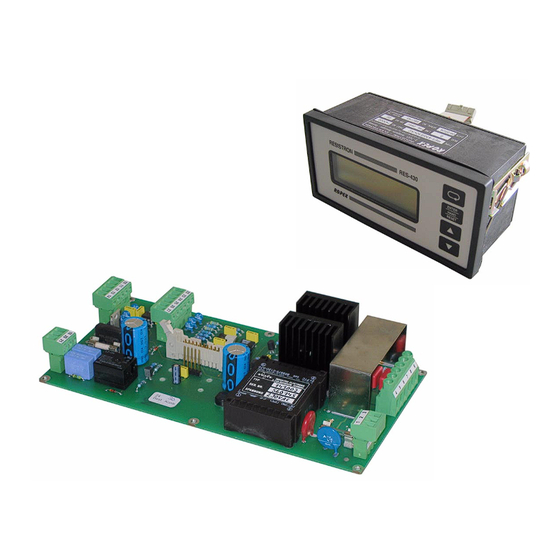
Startup and operation Startup and operation View of the controller 9.1.1 Motherboard Connector for terminal Terminals Connector for piggyback module (optional data interface) Terminals Nameplate 9.1.2 Front view of the terminal Connecting cables Nameplate Mounting clamps Display Operator keys Page 16 RES-430... -
Page 17: General Controller Configuration
It is set with step 201 in (e.g. Alloy-20) the Configuration menu: 3. Temperature coefficient 1400ppm The following settings are possible: (e.g. ROPEX CIRUS system) English, German, Italian 4. Temperature coefficient 1700ppm The language which is selected in this menu (e.g. ROPEX CIRUS system) remains set even if the factory settings are 5. -
Page 18: Time Control (Timer Function)
Startup and operation Menu step 204 is only available if you It is only possible to start a heating process selected "Variable" with step 203. with the "HAND" key on the controller. The timeout of the internal time control cannot be 9.2.4 Configuration of the temperature started with this key. - Page 19 Startup and operation 9.3.3 Setting the heatsealing time The direction arrow disappears again at the end of the cooling phase (i.e. at the end of the internal timeout). The heatsealing time can be set in the range from 0 to The current condition of relay K1 (or the optional 99.9s with step 104 in the Settings menu.
- Page 20 Startup and operation The various cooling modes are shown below: The possible settings are as follows: 1. "Cooling temp. in °C" START (if setting with menu step 210 = "Absolute") signal The cooling phase of the internal timeout ends when the ACTUAL temperature of the heatsealing band falls below the SET temperature.
- Page 21 Startup and operation These two alternatives are shown below: solenoid drive) closes as soon as the "START" signal is activated and remains closed until the end START of the parameterized timeout (i.e. until the end of the signal cooling phase). 2.
-
Page 22: Temperaturediagnosis
Startup and operation The possible settings are shown below: If the actual temperature is outside the specified tolerance during the parameterized monitoring time, START the heatsealing cycle is immediately interrupted and an signal alarm is indicated on the display. This monitoring function serves to maintain a constant temperature. -
Page 23: Load Cell Interface / Temperature Sensor
Startup and operation Load cell interface / separately by means of steps 242+243 in the Configuration menu. temperature sensor 9.5.1 General RES-430 Load cell The RES-430 controller can be connected to a load cell and a temperature sensor. The load cell is used to +Vcc measure the closing force of the heatsealing mechanism. -
Page 24: Heatsealing Band
Startup and operation 4. "End of cooling phase" immediately output by the controller if this maximum A single force diagnosis takes place at the end of temperature is exceeded. the cooling phase. RES-430 Alarm signal Temp. Force sensor Maximum force ϑ... -
Page 25: Startup Procedure
47 to 63Hz. recooling, the controller usually indicates a value less 3. Heed the information contained in the ROPEX than 20°C. Repeat the "AUTOCAL" function. The Application Report as well as the specifications for heatsealing band has now been burned in and the the heatsealing band that is used (section 9.2... - Page 26 104…106, 111…113, 211, section 9.2 "General controller configuration" on 302, 303 page 17 and ROPEX Application Report). Repeat the zero point calibration after the controller has Alarm signal with error codes Fault diagnosis been configured correctly.
-
Page 27: Controller Functions
ENTER HAND HAND function: Manual mode RESET RESET function: Reset after alarm ROPEX "UP" and "DOWN" keys for setting values Press (< 2 sec.): Slow change Hold (> 2 sec.): Fast change LC display, 4 lines, multilingual 10.2 Display switched on. This message also includes details of the software version. - Page 28 Controller functions 10.2.2 Display in home position in other words it indicates the SET temperature as a digital value and the ACTUAL temperature as a digital If no settings are entered on the controller and no alarm value and a dynamic bar. signals are present, the display is in the home position, Specified heatsealing Icon indicates that NO...
-
Page 29: Navigation In The Menus
Controller functions 10.3 Navigation in the menus structure, providing a controller alarm is not active. In this case, the Alarm menu is opened instead. If the display is in the home position or an alarm is 10.3.1 Navigation in menus without an indicated and you press the "MENU"... - Page 30 Controller functions 10.3.2 Navigation in menus with an alarm can then activate the "AUTOCAL" function by pressing the "ENTER" key ( section 10.8 "Automatic zero If an alarm is signaled, the controller switches to the calibration (AUTOCAL)" on page 35). Alarm menu.
-
Page 31: Menu Structure
Controller functions 10.4 Menu structure Settings Configuration Power-up message Home position Language 1) Force sensor active 2) Force sensor not Display actual force Factory settings active 3) Time control: OFF 101 Heatsealing temp. Alloy 4) Time control: ON 5) TCR not variable 6) TCR = variable 102 Preheating temp. - Page 32 Controller functions Configuration Continued from previous page 240 Sealing mode s/d Sensor mode 1) Force sensor or force and tem- Minimum force perature sensor active 2) Temp. sensor Maximum force active 3) No sensors active Force tare 4) Temp. sensor not active Reference force 246 Max.
-
Page 33: Two-Digit Numbering System
Controller functions 10.5 Two-digit numbering system revision 006. Three-digit numbers were introduced in SW revision 007 to improve the clarity of the menu up to SW revision 006 structure. The table below compares the two numbering systems: A system of one and two-digit numbers was used for the Settings and Configuration menus up to SW Numbering Numbering... -
Page 34: Temperature Setting
Controller functions 10.6 Temperature setting In addition, the RES-430 outputs an analog 0…10VDC signal, which is proportional to the real ACTUAL (set point selection) temperature, at terminals 10+11. The heatsealing temperature can be set by means of menu step 101. RES-430 The maximum value of the setting range is limited... -
Page 35: Automatic Zero Calibration
Controller functions this function by selecting step 107 in the Settings menu 0 - 500°C range °C and then pressing the "ENTER" key. The initial temperature (ambient temperature) of the heatsealing bar(s) which is currently valid for calibration can be set beforehand in the 0…40°C range using the "UP"... -
Page 36: Foot Switch" Signal
Controller functions 10.9 "FOOT SWITCH" signal activating and deactivating the "FOOT SWITCH" signal. The hold time is deactivated if the value entered is "0" (factory setting). The "FOOT SWITCH" signal is activated by means of a control contact at terminals 12+13. The time control must energize relay K1 within parameterized... -
Page 37: Cycle Counter
Controller functions 10.12 Cycle counter change configuration with step 240, you must run the AUTOCAL function with step 107. If not, the controller will no Each activation of the "START" signal during operation longer function correctly. is detected by a cycle counter integrated in the controller. -
Page 38: Locking The "Hand" Key
Controller functions 10.15 Locking the "HAND" key The various hold modes are shown below: START (As of SW revision 007) signal The "HAND" key function can be configured with step 213 in the Configuration menu when the display is in the home position. This prevents the heatsealing bands from being heated if the "HAND"... -
Page 39: Undervoltage Detection
Controller functions the power-up message is displayed). The display then a standby mode. No more heatsealing processes take shows a message confirming that the lock function has place and no more measuring impulses are generated. been canceled. The display changes to indicate this. In the factory setting the Configuration menu is not The main menu is displayed again, and operation is locked. - Page 40 Controller functions 10.17.1 Example The heatsealing process is started by means of a foot switch. The example below illustrates the basic design of a pneumatically operated L-sealer with a solenoid valve. Solenoid valve Cylinder START contact Relay K1 Sealing bar START Heatsealing band Film...
- Page 41 Controller functions The timing sequence can be represented as follows: Required controller settings: The following controller settings are required for time FOOT SWITCH control (the basic settings such as the temperature signal range, alloy etc. should already have been entered). The settings should be undertaken in the specified order.
-
Page 42: System Monitoring / Alarm Output
Controller functions 10.18 System monitoring / alarm output Since a temperature indication is no longer necessary if a fault occurs, the actual value output is used to display error codes in the event of an alarm. To increase operating safety and to avoid faulty 13 voltage levels are offered for this purpose in the heatsealing, controller... - Page 43 Controller functions RES-430 Page 43...
- Page 44 Controller functions Page 44 RES-430...
-
Page 45: Fault Areas And Causes
- Conducting part bypasses heatsealing band completely Controller voltage measurement - Check impulse transformer specification, signal outside permissible range heed information in ROPEX Application Report Controller current measurement - Check impulse transformer specification, signal outside permissible range heed information in ROPEX Application Report... -
Page 46: Factory Settings
Factory settings Factory settings 11.1 Ropex settings The RES-430 RESISTRON temperature controller is configured in the factory as follows (Ropex settings): Values in the Settings Settings menu and Configuration Step 101 Heatsealing temperature: 0°C menus Step 103 Starting delay: Step 104 Heatsealing time:... -
Page 47: Customer Settings
1. "Restore Ropex settings" (•) approximately 2seconds. Selecting this option restores the menu values listed in section 11.1 "Ropex settings" on page 46. These values correspond to the factory settings with which the controller was delivered. 2. Define customer settings"... -
Page 48: How To Order
T-430 terminal Line filter LF- 06480 Continuous current 6A, 480VAC, Art. No. 885500 Impulse transformer See ROPEX Application Report for design and ordering information Optional data interface (piggyback module) Art. No. 743099 Sub-D connecting cable for optional data interface... -
Page 49: Index
Controller configuration Power supply Controls Principle of operation Cooling mode Customer settings Relay K1 Replacing heatsealing band Data interface Ropex settings Degree of protection Delay time, force diagnosis Delay time, temperature diagnosis Set point selection Dimensions Single/double sealing Display Software... -
Page 50: Wiring Diagram With Solenoid Drive
Index View Wiring Visualization software Wiring diagram with relay K1 Wiring diagram with solenoid drive Page 50 RES-430...
Need help?
Do you have a question about the Resistron RES-430 Series and is the answer not in the manual?
Questions and answers