
Related Manuals for ATN Thermal Entry Wizard

Summary of Contents for ATN Thermal Entry Wizard
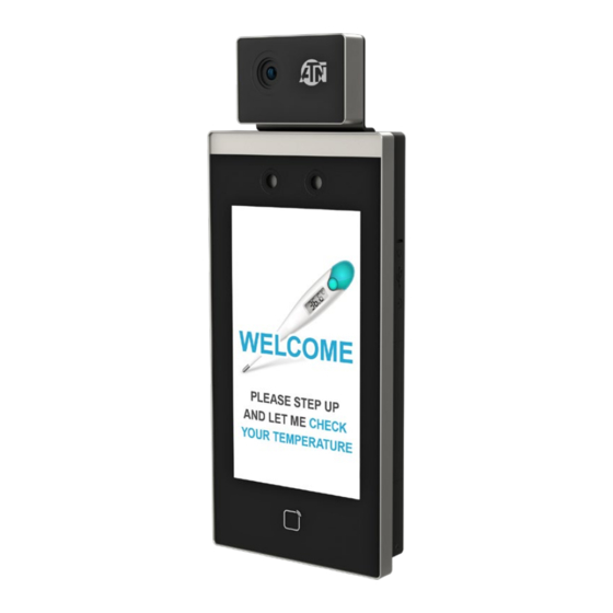
- Page 1 ATN Thermal Entry Wizard TOUCHLESS FEVER DETECTOR M A N U A L AMERICAN TECHNOLOGIES NETWORK CORP .
-
Page 2: Table Of Contents
TA B L E O F C O N T E N T S TA B L E O F C O N T E N T S 6 .3 . 1 . Set Network Parameters . . . . . . . . . . . . . . . . . . . . . . . . . . . . . . 32 Legal Information . - Page 3 7 .9 .3 . Search Historical Events . . . . . . . . . . . . . . . . . . . . . . . . . . . . . . 96 ATN Corp . assumes no responsibility or liability for any errors or inaccuracies that may appear in this book .
-
Page 4: Legal Information
L E G A L I N F O R M AT I O N During the use of device, personal data will be collected, stored, and pro- cessed . To protect data, the development of ATN Corp . devices incorporates ABOUT THIS MANUAL privacy by design principles . -
Page 5: Fcc Conditions
• Connect the equipment into an outlet on a circuit different from that to • Please use the power adapter, which is provided . This equipment is in- which the receiver is connected . tended to be supplied from the Class 2 surge protected power source rat- ed DC 12V, 3A . -
Page 6: Chapter 1. Overview
• Biometric recognition products are not 100% applicable to anti-spoofing C H A P T E R 2 . A P P E A R A N C E environments . If you require a higher security level, use multiple authen- tication modes . -
Page 7: Chapter 3. Installation
Table 2-1. Description of Face Recognition Terminal Name USB Interface Card Swiping Area Touch Screen Camera IR Light White Light Thermographic Module IR Light Camera Figure 3-1. Connect Thermographic Module TAMPER 3 . Use 5 supplied screws (4_KA4×22-SUS) to secure the mounting plate on Thermographic Module Interface the gang box . -
Page 8: Surface Mounting
6 . Use 2 supplied screws (SC-M4×14 .5TP10-SUS) to secure the device and the mounting plate . NOTE When the screw’s head is beneath the device surface, the device is secured. Figure 3-4. Mounting Template Figure 3-3. Secure Device 3 . Insert the screw sockets of the setscrews in the drilled holes . NOTE The installation height here is the recommended height. -
Page 9: Chapter 4. Wiring
Figure 3-7. Secure Device NOTE The installation height here is the recommended height. You can change it according to your actual needs. For easy installation, drill holes on mounting surface according to the supplied mounting template. C H A P T E R 4 . W I R I N G Figure 3-6. -
Page 10: Terminal Description
If the cable size is 12 AWG, you should use a 12 V power supply. And the The descriptions of the terminals are as follows: distance between the power supply and the device should be no more Table 4-1. Terminal Descriptions than 40 m. -
Page 11: Wire Secure Door Control Unit
NOTE You should set the face recognition terminal’s Wiegand direction to “Input” to connect to a Wiegand card reader. If connects to an access controller, you should set the Wiegand direction to “Output” to transmit authentication information to the access controller. For details about Wiegand direction settings, see Setting Wiegand Parameters in Communication Settings. -
Page 12: Wiring Diagram Of Door Locked When Powering Off
Figure 4-6. Wiring Device Figure 4-4. Wire Device Figure 4-7. Wiring Secure Door Control Unit Figure 4-5. Wire Secure Door Control Unit 4.4.2. Wing Diagram of Door Locked When Powering Off Type 2 Lock Type: Cathode Lock, Electric Lock, and Electric Bolt (NC) Security Type: Door Locked When Powering Off Scenario: Installed in Entrance/Exit with Fire Linkage NOTE... -
Page 13: Chapter 5. Activation
The default values of the device are as follows: • The default IP address: 192 .0 .0 .64 • The default port No .: 8000 • The default user name: admin 5.1. ACTIVATE VIA DEVICE If the device is not activated, you can activate the device after it is powered on . -
Page 14: Activate Via Sadp
• After activation, if you need to add the device to the client software or oth- 5 . Modify IP address of the device . er platforms, you should edit the device IP address . For details, see Com- a) Select the device . munication Settings . -
Page 15: Login
6.2.1. Login for First Time You should login into the system before other device operations . Steps 1 . Long tap on the initial page for 3 s to enter password entering page . 2 . Tap the Password field and enter the device activation password . 3 . -
Page 16: Login By Administrator
6.2.2. Login by Administrator After you add the administrator for the device, only the administrator can log- in the device for device operation . Steps 1 . Long tap on the initial page for 3 s to enter the admin login page . Figure 6-4. -
Page 17: Set Network Parameters
6.3.1. Set Network Parameters 3 . Select an peripheral type according to your actual needs . You can set the device network parameters, including the IP address, the NOTE subnet mask, and the gateway . Controller represents the access controller; Unit represents the secure Steps door control unit and Reader represents the card reader. -
Page 18: User Management
6.4. USER MANAGEMENT NOTE The employee ID should be less than 32 characters. And it can be a On the user management interface, you can add, edit, delete, and search combination of lower letters, upper letters, and numbers. the user . The employee ID should not be duplicated. -
Page 19: Add Card
NOTE NOTE Make sure your face picture is in the face picture outline when adding The card No. cannot be empty. the face picture. Up to 20 characters are allowed in the card No. Make sure the captured face picture is in good quality and is accurate. The card No. -
Page 20: Set Authentication Mode
6.4.5. Set Authentication Mode After adding the user’s face picture, password, or other credentials, you should set the authentication mode and the user can authenticate his/her identity via the configured authentication mode . Steps 1 . Long tap on the initial page and log in the backend . 2 . -
Page 21: Import And Export Data
6.6. IMPORT AND EXPORT DATA You can authenticate identity via 1:1 matching or 1:N matching . 1:N Matching On the Transfer page, you can export the event, the user data, the user pic- Compare the captured face picture with all face pictures stored in the device . ture, and the captured picture to the USB flash drive . -
Page 22: System Settings
6.8. SYSTEM SETTINGS 6.8.2. Set Face Picture Parameters You can set the face 1:N (security) level, 1:1 (security) level, recognition in- On the System Settings page, you can set the system basic parameters, the terval, liveness security level, WDR level, pupillary distance, face with mask face parameters, and upgrade the firmware . -
Page 23: Set Time
Table 6-3. Face Picture Parameters Set the matching threshold when authenticating via ECO mode 1:1 matching mode . The larger the value, the smaller ECO Mode (1:1) Parameter Description the false accept rate and the larger the false rejection rate . By default, the value is 75 . -
Page 24: Maintenance
The device can also be upgraded by unplugging the device, plugging in USB, and rebooting . The upgrade will occur automatically . NOTE Do not power off during the device upgrade. The upgrading file should be in the root directory. The upgrading file name should be digicap.dav. -
Page 25: Log Query
6.10.3. Log Query You can search the authentication logs within a period of time by inputting employee ID, card No ., or user name . Steps 1 . On the Home page, tap Log (Log) to enter the Log page . Figure 6-16. -
Page 26: Set Manual Attendance Via Device
Before You Start c) Select Monday, Tuesday, Wednesday, Thursday, Friday, Saturday, or Sunday . Add at least one user and set the user’s authentication mode . For details, d) Tap the select date and set the selected attendance status’s start time . see User Management . -
Page 27: View System Information
6.12. VIEW SYSTEM INFORMATION View the Open Source License information . Tap Info . (System Information) → License to enter the Open Source Soft- View device capacity, device information, and the open source software li- ware Licenses page . cense . View Device QR Code View Capacity You can add the device to the mobile client by scanning the device QR code . -
Page 28: Device Management
7.2. DEVICE MANAGEMENT special characters) in order to increase the security of your product. And we recommend you change your password regularly, especially in The client supports managing access control devices . the high security system, changing the password monthly or weekly can better protect your product. - Page 29 CAUTION And we recommend you change your password regularly, especially in the high security system, changing the password monthly or weekly can The password strength of the device can be automatically checked. better protect your product. We highly recommend you change the password of your own choosing (using a minimum of 8 characters, including at least three kinds of fol- Proper configuration of all passwords and other security settings is the lowing categories: upper case letters, lower case letters, numbers, and...
- Page 30 Password NOTE This function should be supported by the device. Enter the device password . 5 . Optional: Check Synchronize Time to synchronize the device time with CAUTION the PC running the client after adding the device to the client . The password strength of the device can be automatically checked.
-
Page 31: Reset Device Password
7.3. GROUP MANAGEMENT Password Enter the device password . The client provides groups to manage the added resources in different CAUTION groups . You can group the resources into different groups according to the re- sources’ locations . The password strength of the device can be automatically checked. We highly recommend you change the password of your own choosing Example (using a minimum of 8 characters, including at least three kinds of fol-... -
Page 32: Remove Resources From Group
Before You Start Hover the mouse on an added organization and click Import the resources to group . Refer to Import Resources to Group . Edit Organization edit its name . Steps 1 . Enter the Device Management module . Hover the mouse on an added organization and click delete it . -
Page 33: Upload A Face Photo From Local Pc
7.4.4. Upload a Face Photo from Local PC 5 . Select Local as the card issuing mode . When adding person, you can upload a face photo stored in local PC to the client as the person's profile . Steps 1 . -
Page 34: Collect Face Via Access Control Device
6 . Collect face . a) Face to the camera of the selected access control device and make sure your face is in the middle of the collecting window . b) Click to capture a photo . c) Click OK to save the captured photo . 7 . -
Page 35: Customize Person Information
NOTE 5 . Check the person's operation permissions . Super User Enter the person's basic information first. For details about configuring person's basic information, refer to Configure Basic Information. If the person is set as a super user, he/she will have authorization to access all the doors/floors and will be exempted from remaining closed restrictions, all b) In the Custom Information panel, enter the person information . -
Page 36: Import And Export Person Identify Information
NOTE • Click Add and New to add the person and continue to add other persons . The (folder of) face pictures should be in ZIP format. 7.4.11. Import and Export Person Identify Information Each picture file should be in JPG format and should be no larger than You can import the information and pictures of multiple persons to the client 200 KB. -
Page 37: Get Person Information From Access Control Device
7.4.16. Get Person Information from Access Control Device Steps If the added access control device has been configured with person infor- 1 . Enter Person module . mation (including person details and issued card information), you can get the 2 . Click Batch Issue Cards . person information from the device and import them to the client for further op- All the added persons with no card issued will be displayed in the right panel . -
Page 38: Set Access Group To Assign Access Authorization To Persons
Local Mode: Issue Card by Card Enrollment Station 3 . In the Name text field, create a name for the access group as you want . Connect a card enrollment station to the PC running the client . You can 4 . -
Page 39: Configure Advanced Functions
Steps d) View the applying status in the Status column or click Applying Status to view all the applied access group(s) . 1 . Click Access Control → Advanced Function → Device Parameter . NOTE NOTE You can check Display Failure Only to filter the applying results. If you can find Device Parameter in the Advanced Function list, Hover the cursor on the Advanced Function, and then Click to select the... - Page 40 Configure Parameters for Door NOTE The door or floor's status duration settings will be copied to the After adding the access control device, you can configure its access point (door) parameters . selected door as well. Steps Configure Parameters for Card Reader 1 .
-
Page 41: Configure Multi-Factor Authentication
Face 1:N Matching Threshold 7.6.2. Configure Multi-Factor Authentication Set the matching threshold when authenticating via 1:N matching mode . The You can manage the persons by group and set the authentication for multi- larger the value, the smaller the false accept rate and the larger the false rejec- ple persons of one access control point (door) . -
Page 42: Configure First Person In
Perform this task when you want to configure opening door with first person . Steps 1 . Click Access Control → Advanced Function → First Person In to enter the First Person In page . 2 . Select an access control device in the list on the left panel . 3 . -
Page 43: Configure Device Parameters
Set Log Uploading Mode 2 . Select a card reader as the beginning of the path in the First Card Read- er field . You can set the mode for the device to upload logs via ISUP protocol . 3 . Click of the selected first card reader in the Card Reader Afterward col- Steps umn to open the select card reader dialog . - Page 44 Before setting the capture parameters, you should set the picture stor- Set Parameters for Face Recognition Terminal age first to define where the event triggered pictures are saved. For details, For face recognition terminal, you can set its parameters including face pic- refer to Set Picture Storage in the user manual of the client software.
-
Page 45: Configure Linkage Actions For Access Control
1 . Enter the Access Control module . 3 . Select an access control device in the device list and click Wiegand to en- ter the Wiegand Settings page . 2 . On the navigation bar on the left, enter Advanced Function → More Pa- rameters . -
Page 46: Configure Device Actions For Access Event
7.7.3. Configure Device Actions for Card Swiping a) Select the event(s) and click Edit Linkage to set the client actions when the events triggered . You can set the access control device's linkage actions for the specified card swiping . When you swipe the specified card, it can trigger the host buzzer, and Audible Warning other actions on the same device . -
Page 47: Door Control
Steps 7.8.1. Control Door Status You can control the status for a single door, including opening door, closing NOTE door, remaining the door open, and remaining the door closed . It should be supported by the device. Steps 1 . Click Access Control → Linkage Configuration . 1 . -
Page 48: Event Center
7.9.2. View Real-Time Events 2 . Optional: Check the event type and event status so that these events will show in the list if the events are detected . The events of unchecked type The real-time event information received by the client of the connected re- or status will not be displayed in the list . -
Page 49: Search Historical Events
7.9.3. Search Historical Events Access Control For the events of access control, you can set the following filter conditions: In the Event Search module of the event center page, you can search the historical events via time, device type, and other conditions according to the device, priority, status, event type, card reader type, person name, card no ., specified device type, and then process the events . -
Page 50: Remote Configuration (Web)
NOTE 7.10.2. Change Device Password After an event is handled, the Handle button will become Add Remark, You can change the device password . click Add Remark to add more remarks for this handled event. Before You Start Make sure the device is activated . For details, see Activation . 6 . -
Page 51: System Maintenance
NOTE On the Device for Management page, click Remote Configuration → System If you select Card reader as the device type, you should also select a → Time → DST to enter the DST tab . card reader No. from the drop-down list. Enable DST and you can edit the DST bias time, the DST start time, and end The upgrade will lasts for about 2 min. -
Page 52: Report Strategy Settings
DHCP 7.10.11. Set Relay Parameters Click Maintenance and Management → Device to enter the device list . If you disable the function, you should manually set the device's IPv4 ad- dress, IPv4 subnet mask, IPv4 default gateway, MTU, and port . Click to enter the remote configuration page . -
Page 53: Configure Face Picture Parameters
Score Set the matching threshold when authenticating via ECO mode 1:N match- ing mode . The larger the value, the smaller the false accept rate and the larg- The device will score the captured picture according to the yaw angle, pitch er the false rejection rate . -
Page 54: Operate Relay
7.10.19. Operate Relay Steps 1 . Click Maintenance and Management → Device to enter the device list . 2 . Click to enter the remote configuration page . 3 . Click Operation → Relay . 4 . Enable or disable the relay . 7.10.20. -
Page 55: Dimension
3 . Avoid backlight, direct and indirect sunlight . C . D I M E N S I O N... - Page 56 For customer service and technical support, please contact American Technologies Network Corp. 1341 San Mateo Avenue, South San Francisco, CA 94080 phone: 800-910-2862, 650-989-5100 e-mail: service@atncorp .com www.atncorp.com ©2020 ATN Corporation...
Need help?
Do you have a question about the Thermal Entry Wizard and is the answer not in the manual?
Questions and answers