Table of Contents
Advertisement
Quick Links
Advertisement
Table of Contents

Subscribe to Our Youtube Channel
Related Manuals for SAB Heli Division GOBLIN KRAKEN NITRO 580


Summary of Contents for SAB Heli Division GOBLIN KRAKEN NITRO 580
-
Page 2: Very Important
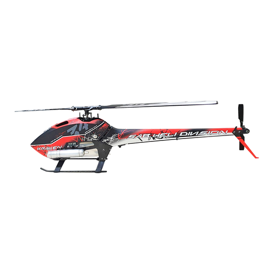
SAB Heli Division cannot be held responsible for any issues with your model and will not provide support unless you register your model. - Page 3 INTRODUCTION GOBLIN KRAKEN 580 NITRO TECHNICAL SPECIFICATIONS 1175mm • RTF Approx. Weight: 3090 g (RTF no fuel). • Cyclic Servos: Mini size 35 mm (Standard size 40mm option ). • Main blade length: 550mm to 600mm ( 570mm included ). •...
-
Page 4: Important Notes
PRODUCT, WHETHER SUCH CLAIM IS BASED IN CONTRACT, WARRANTY, NEGLIGENCE, OR STRICT LIABILITY. Further, in no event shall the liability of SAB Heli Division exceed the individual price of the Product on which liability is asserted. As SAB Heli Division has no control over use, setup, final assembly, modification or misuse, no liability shall be assumed nor accepted for any resulting damage or injury. -
Page 5: Additional Components Required
NOTE FOR ASSEMBLY ADDITIONAL COMPONENTS REQUIRED TOOLS, LUBRICANTS, ADHESIVES INSIDE THE MAIN BOX THERE ARE: Extra Card *Generic pliers. *Engine: .50 to .60 Nitro Heli Engine. *Hexagonal driver, size 1.5, 2, 2.5, 3mm. *Muffer suited for the engine being used. *4/5mm T-Wrench. - Page 6 CARBON ROD ASSEMBLY BAG1 Carbon Rod 2.5x 4x570mm (HC586-S) Threaded Rod M2.5x40mm Threaded Rod M2.5x40mm (HC242-S) (HC242-S) NOTE: 16mm 16mm Aluminum Bushing Aluminum Bushing Approx 602mm Page 5...
- Page 7 ENGINE UNIT ASSEMBLY BAG2.1, FOAM 1 BAG2.2, FOAM 1 ENGINE MOUNT ASSEMBLY CLUTCH UNIT ASSEMBLY Flat Head Cap Screw M3x8mm SECTION (HC134-S) (H0671BM-S) Engine Support Spacer (H1286-S) Clutch Support (H0672-S) Note: Flat Head Cap Counterbore external side. Screw M3x8mm (HC134-S) Clutch (H0670-S) Button Head Cap...
- Page 8 ENGINE UNIT ASSEMBLY BAG2.3 MAIN RATIO ENGINE ASSEMBLY It is possible to have 5 ratios using the following Pulleys: NOTE: H0675BL-28-S 50/28 H0675BL-27-S 50/27 Do not add loctite on the engine shaft H0675BL-26-S 50/26 Socket Head Cap H1213-S: OWB Pulley 54T 54/27 Screws M3x10mm H1213-S: OWB Pulley 54T...
- Page 9 ENGINE UNIT ASSEMBLY BAG2.4 INSTALLATION OF THE RPM SENSOR On the 580 nitro it is possible to use two different methods to install an RPM sensor. The first is a backplate sensor as demonstrated in the picture on the right. P.S: Not all YS engines can support this method.
- Page 10 ENGINE UNIT ASSEMBLY BAG3.1 FAN CASE SX ASSEMBLY FAN CASE DX ASSEMBLY The fan case is designed symmetrically. To install the servo it is necessary to cut a small part in the right case as show in the Figure. Socket Head Cap Flat Head Cap Screw M3x10mm Screw M3x8mm...
-
Page 11: Linkage Assembly
ENGINE UNIT ASSEMBLY BAG3.2 Rotate servo in place Approx 72mm 15-17mm Servo Horn Uniball M2 (H0538-S) Servo Spacer (H1223-S) SERVO (HC044-S) Uniball M2 (H0538-S) Socket Head Cap Screw M2.5x12mm Servo Spacer LINKAGE (HC026-S) (H1223-S) ASSEMBLY LINKAGE ASSEMBLY Plastic Ball Link M2 Thread Rod M2x56mm Plastic Ball Link M2 (H0403-S) -
Page 12: Main Frame Assembly
MAIN FRAME ASSEMBLY BAG4 MAIN FRAME ASSEMBLY Engine Spacer (H0678-S) Socket Head Cap Screw M4x10mm Cable Pass (HC102-S) (HA010-S) Engine Spacer (H0678-S) Button Head Cap Screw M3x6mm (HC096-S) Button Head Cap Engine Spacer Screw M3x6mm (H0678-S) (HC096-S) Main Frame (H1281-S) Cable Pass (HA010-S) ENGINE... -
Page 13: Tank Assembly
TANK ASSEMBLY TANK LINE ASSEMBLY BAG5.1 Fuel Clunk Filter Tube 2.4x Fuel Rubber Fuel Nipple [H0705] [HC475] [HC474] [H0708] [H0706] Aprrox 85mm Tank Column Mount (H1283-S) Bushing (H1282-S) Tank Rubber (H1282-S) Set Screw M3x20mm (HC150-S) NOTE: NOTE: Tighten the tank columns Install the fuel grommet into until they are fully tightened the tank, then gently insert the... - Page 14 TANK UNIT ASSEMBLY BAG5.2 Socket Head Cap Screw M3x8mm (HC050-S) FRAME Socket Head Cap ASSEMBLY Screw M3x8mm Finishing Washer M3 (HC050-S) (H0007-S) Finishing TANK Washer M3 ASSEMBLY (H0007-S) Finishing Washer M3 (H0007-S) Socket Head Cap Screw M3x8mm (HC050-S) NOTE: Only use a backplate pressurized tank setup if your engine supports it. Consult your engine manual before plumbing your tank in this way.
-
Page 15: Landing Gear Assembly
LANDING GEAR ASSEMBLY BAG6 LANDING GEAR ASSEMBLY MAIN FRAME ASSEMBLY Plastic Landing Gear Support (H1226-S) Canopy Front Block (H1227-S) Frame Spacer (H1324-S) Plastic Landing Gear Support (H1226-S) Landing Gear Plug Finishing [H1274] Washer M2.5 Selt Tapping Cap (H0255-S) Screws M3x10mm (HC136-S) Finishing Washer M2.5... - Page 16 TRANSMISSION GROUP ASSEMBLY Foam 1, BAG7 TRANSMISSION GROUP ASSEMBLY AND VERIFIED Socket Head Cap Socket Head Cap Screw M3x8mm Screw M2.5x8mm The unit is ready to use Front Servo Mount 35mm (HC050-S) (HC020-S) Check page 40 for more Swashplate Guide information.
- Page 17 SWASHPLATE SERVOS ASSEMBLY BAG8 Socket head cap screw M2.5x8mm SERVO ASSEMBLY (HC020-S) Servo spacer The linkage ball must be positioned 17-18 mm out on the servo arm. The recommended servo arm (H1223-S) to use is: SAB p/n [HA050/HA051]. Ensure the alignment of the servo arms (and sub trim set) before installing the servos in the model. Proceed with installation following the instructions below.
- Page 18 HEAD ASSEMBLY Foam 2, BAG9 UNIBALL RADIUS ARM ASSEMBLY ...X2 RADIUS ARM ASSEMBLY ...X2 LINKAGE ROD ASSEMBLY ...X2 Flanged Bearing Flanged Bearing Spacer Arm 2.5x 6x2.5mm Linkage Rod Radius Arm 2.5x 6x2.5mm 2.5x 4x6.3mm (HC400-S) M2.5x33mm (H0204BM-S) (HC400-S) (H0237-S) Plastic Ball Link (H0066-S) Plastic Ball Link (H0066-S)
-
Page 19: Head Assembly
HEAD ASSEMBLY Foam 2, BAG10 It is a normal ( especially with the 90° + 90° O-ring set-up ) to feel tight after initial assembly as the axial preload is usually high when the helicopter is brand new. The preload will loosen up after 5-10 flights allowing the system to become smooth. Button Head Cap Screw M6x10mm (HC122-S) -
Page 20: Tail Pitch Slider
TAIL GROUP ASSEMBLY Foam 2, BAG11 Oring 90 Shore Tail Shaft (HC594-S) (H0227-S) It is a normal for the tail to feel a bit tight after initial assembly as the tail spindle Spacer preload is usually high when the helicopter is brand new. 6.9x0.5mm Spindle Shaft The preload will loosen up after 5-10 flights allowing the system to become smooth. - Page 21 TAIL GROUP ASSEMBLY Foam 2, BAG12 Tail Case Spacer (H1239-S) Tail Side Plate (H1240-S) Tail Pulley 23T (H1272-S) Socket Head Cap Screw M2.5x6mm TAIL ROTOR (HC018-S) ASSEMBLY Set Screw M3x6mm Uniball M3 (HC144-S) (H0065-S) Socket Head Cap Screw M2x6mm (HC004-S) NOTE: The set screw must align with the hole in the tail shaft...
- Page 22 TAIL GROUP ASSEMBLY BAG13 Tail Belt 1722mm HTD3 6mm (HC592-S) Socket Head Cap Screw M2.5x8mm (HC020-S) Tail Fin (H1243-S) Page 21...
-
Page 23: Tail Boom Assembly
TAIL BOOM ASSEMBLY Foam 1, BAG14 Bolt M8x20mm (HC165-S) Kraken 580 Nitro Boom (H1382-S) Boom Block Support Bolt M8x14mm (H1224-S) (HC164-S) Nut M8 (HC224-S) Washer 14x0.2mm (HC228-S) NOTE: Use 1 or 2 shims each side to optimize the contact. Use this special Secure the Nut tool to apply the Block with a small... - Page 24 TAIL BOOM ASSEMBLY BAG15 BOOM GROUP ASSEMBLY Finishing Socket Head Cap Washer M3 Screws M3x10mm (H0007-S) (HC056-S) Double Sided Tape Finishing Washer M3 TAIL GROUP (H0007-S) ASSEMBLY Socket Head Cap Double LOCKING ELEMENT TAIL Screws M3x10mm Sided Tape (H0249-S) (HC056-S) Page 23...
-
Page 25: Tail Servo Assembly
TAIL BOOM ASSEMBLY BAG16 Self Head Cap Screw M3x12mm TAIL SERVO ASSEMBLY Socket Head (HC549-S) Screw M3x6mm (HC044-S) Socket Head Servo Arm Servo Spacer Screw M2x6mm (HA050-S) (H0075-S) (HC004-S) Standard Uniball M2 Servo (H0064-S) TAIL SERVO The distance between the center of the servo spline Tail Servo Block and the ball must be around 18mm. - Page 26 TAIL BOOM ASSEMBLY BAG17 Before installing the plastic link on the threaded rod, be sure that you have waited at least 12 hours for the glue to fully cure. Plastic Ball Link Plastic Ball Link (H0066-S) (H0066-S) Approx 628mm NOTE: NOTE: Before installing the plastic link onto the ball, be sure the tail push rod moves smoothly.
- Page 27 ASSEMBLING OF THE MODULES BAG18 Canopy Base (H1101-S) TIPS: M3x6 Using a 4/5mm shaft, you can tension the motor belt. (HC044) TRANSMISSION GROUP Push the shaft on right side and then tighten the bolts. ASSEMBLY Socket Head Cap Screw M2.5x10mm CF Canopy Base (HC022-S) (H1221-S)
-
Page 28: Swashplate Assembly
ASSEMBLING OF THE MODULES BAG19, FOAM 2 Socket Head Cap Screw M2.5x12mm SWASHPLATE ASSEMBLY (HC026-S) Uniball M3 HEAD (H0065-S) ASSEMBLY Metric Hex Nylon Nut M4 (HC212-S) Socket Head Cap Socket Head Cap Screw M4x20mm Screw M2.5x12mm Swashplate SET (HC544-S) (HC026-S) (H1204-S) SWASHPLATE ASSEMBLY... - Page 29 ASSEMBLING OF THE MODULES BAG20 LINKAGE ROD ASSEMBLY ... x3 Approx 45mm Plastic ball link Plastic ball link (H0066-S) (H0066-S) Set Screw M2.5x18mm (HC140-S) Initial length for the rods from the servos to the swash plate. LINKAGE ROD ASSEMBLY Page 28...
- Page 30 ASSEMBLING OF THE MODULES BAG21 To fit the tail belt, loosen the tail case by loosening the 4 M3 screws (Figure 1). *Install the belt onto the tail front pulley, checking the direction of rotation. *Insert and tighten the four M3 screws in the boom plate. *Rotate the tail drive several times by hand.
-
Page 31: Tail Belt Tension
ASSEMBLING OF THE MODULES TAIL BELT TENSION To provide the correct tail belt tension, you can use the "zig-zag" method. Figure 1, Loosen the 2 RED screws and the BLUE and push the tail side plate in according with red arrow. Tighten the BLUE screw while you are pushing. Figure 2, Loosen the 2 RED screws and the YELLOW and push the tail side plate in according with red arrow. - Page 32 ASSEMBLING OF THE MODULES BAG22 X-ROSS PLATE ASSEMBLY Flat Head Cap Screw M2.5x5mm (HC128-S) X-ross Mount (H1380-S) Flat Head Cap Screw M2.5x5mm (HC128-S) X-ross Plate X-ross mount (H1380-S) (H1380-S) X-ross Mount (H1380-S) Socket Head Cap Socket Head Cap Screw M2.5x6mm Screw M2.5x6mm (HC018-S) (HC018-S)
- Page 33 INSTALLATION FBL/RX BAG23, FOAM 1 We suggest installing the flybarless mount without the shock absorber. This will give you the most direct feeling of the model. You can use the small plate to support any separate RX. Socket Head Cap Finishing Screw M2.5x8mm Washer M2.5...
- Page 34 INSTALLATION FBL/RX BAGs 24.1, 28, 29 BAG 29 EXTRA SUPPORT In bag 28, you can find a “3D Printed” antenna support. Flat Head Cap Use it as desired with your RX system. Screws M3x10 Antenna (HC135-S) Battery Backup Support Support [H1134] (H1241-S) Nylon Nut M3...
- Page 35 INSTALLATION FBL/RX BAG24.2 NOTE: Use hot glue to secure the wire connections. Servos Wire Servos Wire Zip-tie [HA058] Tail Servo Wire Follow the illustrated wiring method. Use the servo extension for connecting the tail servo. Gluing of the connector on the carbon support is recommended as show in Figure 2.
-
Page 36: Installation Batteries
INSTALLATION BATTERIES BAG25 Install the muffler before checking the CG. Adjust the battery position so that the CG is located on the main shaft. BATTERIES Use the included double side tape to secure the batteries to the tray. Use the Velcro Strap [HA044-S]. Strap Velcro (HA044-S) - Page 37 INSTALLATION CANOPY BAG26 CANOPY *Install Canopy grommets (Figure.1) and the two quick knobs (Figure.2) *Fit the canopy in the red arrow zone, and insert the knobs. Kraken 580 *Confirm the canopy is secure prior to each flight. Nitro Canopy (H1381-S) Canopy Grommet (HA021-S) NOTE: To keep the canopy perfectly centered on the helicopter,...
- Page 38 IN FLIGHT BAG27 OPERATIONS BEFORE FLIGHT Socket Head Cap Shoulder M4x24mm *Set up the remote control and the flybarless system with utmost care. (HC111-S) *It is advisable to test the correct settings of the remote and flybarless system without main blades or Blade Washer tail blades fitted.
-
Page 39: Maintenance
MAINTENANCE MAINTENANCE Take a look at the red parts. Check them frequently. All other parts are not particularly subject to wear. The lifespan of these components varies according to the type of flying. On average it is recommended to check these parts every 20 flights. In some instances, based on wear, these parts should be replaced every 100 flights. Periodically lubricate the tail slider movement and its linkages as well as the swash plate movement and its linkages. - Page 40 CHECK LIST Check the dampening on the main and Tighten the main blades before flight. Check main hub screws Check Fuel Line tail rotor to be the same as always. (M4x22 and 2xM2.5x12). (Good connection). Ensure they are tight. Check Tail & Motor belt tension. Check the 4 M3x10 Tail group screws.
-
Page 41: Transmission Module
TRANSMISSION MODULE MAIN SHAFT REPLACEMENT TRANSMISSION MODULE The transmission module is supplied assembled and verified, ready to be used. For replacing the main shaft: *Remove the serial number plate *Remove the M4 screw Main Shaft Use SAB HA076 *Remove and replace the main shaft (H1299-S) Grease inside the module. -
Page 42: Spare Parts
SPARE PARTS Finishing Washer M3 Tail Servo Lock Uniball M2 5H6 Uniball M3x4 5H3 Plastic Ball Link [H0007-S] [H0040-S] [H0064-S] [H0065-S] [H0066-S] - 5 x Uniballs M2 5H6. - 2 x Tail Servo Locks. - 5 x Uniball Spacers. - 2 x Servo Spacers. - 5 x Head Cap Screws M2x8mm. - Page 43 SPARE PARTS Pulley Z26-Z28 Engine Frame Spacer SAB Fuel Clunk SAB Fuel Nipple SAB Fuel Stop [H0675-26-27-28-S] [H0678-S] [H0705-S] [H0708-S] [H0715-S] - 1 x Pulley Z26-Z28 - 1 x SAB Fuel Clunk. - 3 x Radial Bearing 12x18x4mm. - 4 x Engine Frame Spacer - 2 x SAB Fuel Clunk Filter.
- Page 44 SPARE PARTS Canopy Kraken 580 Tail Boom Kraken 580 Tail Blade Grips [H1381-S] [H1382-S] [H1233-S] - 2 x Tail Blade Grip. - 4 x Bearing 9x2.5mm. - 2 x Double Sided Tapes. - 2 x Spacer 9x0.5mm. - 1 x Tail Boom Kraken 580. - 1 x Nut Block.
- Page 45 SPARE PARTS Blade Grip Arm 27 Engine Shaft Fan Case Linkage Tail Support Frame Spacer [H1287-S] [H1315-S] [H1324-S] [H1342-S] [H1369-S] - 2 x Blade Grip Arm. - 1 x Fan Case SX. - 1 x Linkage Tail Support. - 2 x Head Cap Screw M4x8. - 1 x Engine Shaft.
- Page 46 SPARE PARTS [HC111-S] [HC122-S] [HC128-S] [HC132-S] [HC134-S] - 8 x Head Cap Shoulder M4x24mm. - 8 x Button Cap Screws M6x10mm. - 8 x Flat Cap Screws M2.5x5mm. - 8 x Flat Cap Screws M3x5mm. - 8 x Flat Cap Screws M3x8mm. [HC136-S] [HC140-S] [HC144-S]...
- Page 47 SPARE PARTS [HC417-S] [HC420-S] [HC425-S] [HC430-S] [HC434-S] [HC437-S] [HC544-S] - 2 x Ball Bearing - 4 x Ball Bearing - 2 x Radial bearing - 2 x Rad Bearing - 2 x Thrust Bearing - 2 x Thrust Bearing 14x4mm. 15x4mm.
Need help?
Do you have a question about the GOBLIN KRAKEN NITRO 580 and is the answer not in the manual?
Questions and answers