Table of Contents
Advertisement
Advertisement
Table of Contents

Related Manuals for SAB Heli Division Goblin RAW 700


Summary of Contents for SAB Heli Division Goblin RAW 700
- Page 2 SAB Heli Division cannot be held responsible for any issues with your model and will not provide support unless you register your model.
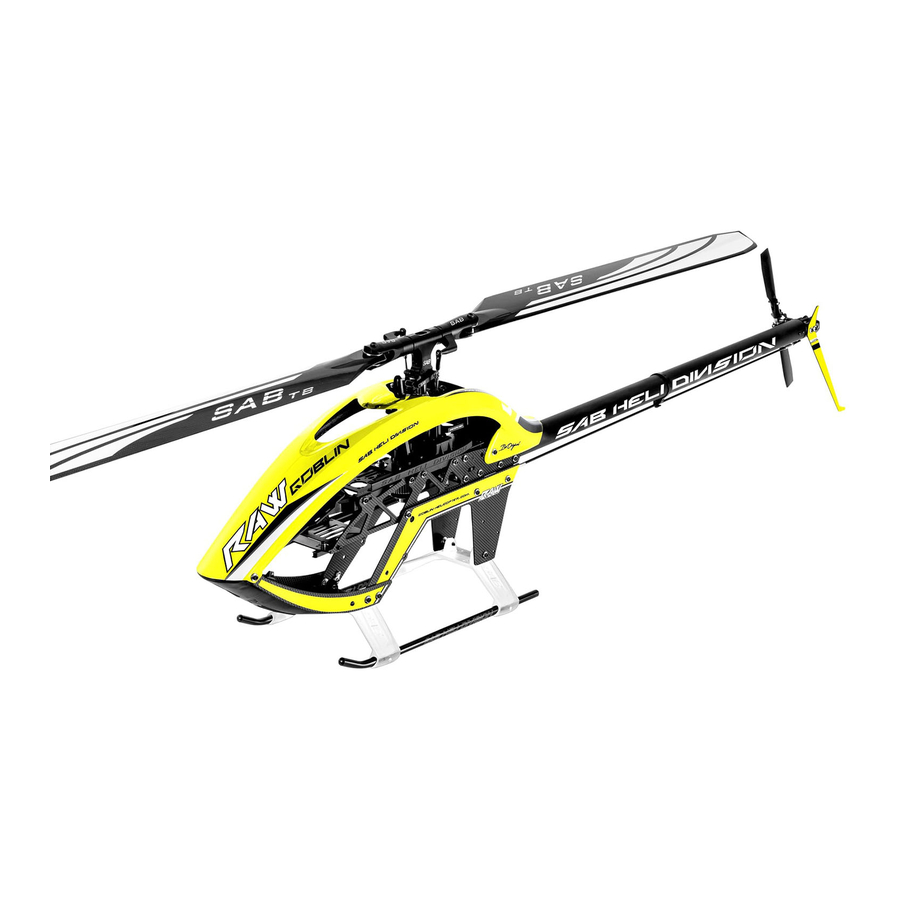
- Page 3 INTRODUCTION GOBLIN RAW TECHNICAL SPECIFICATIONS Typical Motor : 12S, 500-560 Kv, 4525 - 4530 series, (max 62 mm diameter, max 70 mm height). Typical Speed Controller: 12S, 160/200 A Battery compartment: 12S, 4200/5500 mAh. Minimum tail blades size: 105mm (max 56mmx60mmx320mm). Maximum tail blades size: 115mm Suggested weight from 1400gr to 1800gr.
- Page 4 PRODUCT, WHETHER SUCH CLAIM IS BASED IN CONTRACT, WARRANTY, NEGLIGENCE, OR STRICT LIABILITY. Further, in no event shall the liability of SAB Heli Division exceed the individual price of the Product on which liability is asserted. As SAB Heli Division has no control over use, setup, final assembly, modification or misuse, no liability shall be assumed nor accepted for any resulting damage or injury.
- Page 5 NOTE FOR ASSEMBLY ADDITIONAL COMPONENTS REQUIRED TOOLS, LUBRICANTS, ADHESIVES INSIDE THE MAIN BOX THERE ARE: Extra Card *Generic pliers. *Electric Motor *Hexagonal driver, size 1.5, 2, 2.5, 3mm. *4/5mm T-Wrench. *Speed controller *5.5mm Socket wrench (for M3 nuts). Manual *Batteries: 12S – 4200/5500mAh *8mm Hex fork wrench (for M5 nuts).
- Page 6 CARBON ROD ASSEMBLY Box 4, Bag for page 5 Carbon Rod 2.5x 4x720mm (HC606-S) Threaded Rod M2.5x40mm Threaded Rod M2.5x40mm (HC242-S) (HC242-S) 13mm 13mm Aluminum Bushing Aluminum Bushing Approx 746mm Page 5...
- Page 7 TRANSMISSION GROUP ASSEMBLY Box 1, Bag for page 6 TRANSMISSION GROUP ASSEMBLED AND VERIFIED The unit is ready to use Socket Head Cap Rear Servo Mount Socket Head Cap Check page 39 for more Screw M3x8mm (H1207-S) Screw M2.5x8mm information. (HC050-S) (HC020-S) Front Servo Mount...
- Page 8 SWASHPLATE SERVOS ASSEMBLY Box 1, Bag for page 7 SERVO ASSEMBLY The linkage ball must be positioned 18 mm out on the servo arm. The recommended servo arm to Socket Head Cap use is: SAB p/n [HA050/HA051]. Screw M2.5x8mm (HC020-S) Ensure the alignment of the servo arms (and sub trim is set) before installation of the servos in the model.
- Page 9 FRAME GROUP ASSEMBLY Box 3, Bag for page 8 CARBON FRAME The manufacturing process of the carbon parts often leaves micro-burrs and sharp edges. We recommend de-burring the edges to minimize the risks of electrical wire cuts, etc. It is very important to do this along the red lines. LEFT UPPER FRAME ASSEMBLY RIGHT UPPER FRAME ASSEMBLY Main Frame...
- Page 10 FRAME GROUP ASSEMBLY Box 1, Bag for page 9 Finishing Washer M3 (H0007-S) TRANSMISSION ASSEMBLY Socket Head Cap Screw M3x8mm (HC050-S) Finishing Washer M3 (H0007-S) RIGHT UPPER MAIN FRAME ASSEMBLY Socket Head Cap Screw M3x8mm Don't install this screw at this time. (HC050-S) LEFT UPPER MAIN FRAME ASSEMBLY...
- Page 11 HEAD ASSEMBLY Box 1, Bag for page 10 UNIBALL RADIUS ARM ASSEMBLY ...X2 CENTER HUB ASSEMBLY Spindle Flanged Bearing (H0079-S) Spacer Arm 2.5x 6x2.5mm 2.5x 4x6.3mm (HC400-S) eg: Microlube GL261 Uniball Radius Arm Center Hub (H0205-S) (H1043-S) Flanged Bearing 2.5x 6x2.5mm (HC400-S) Oring 90...
- Page 12 HEAD ASSEMBLY Box 1, Bag for page 11 Washer Socket Head Cap CENTER HUB 16x1mm Screw M6x10mm (HC230-S) (HC124-S) ASSEMBLY Bearing 19x5mm (HC422-S) eg: Microlube GL261 Socket Head Cap Washer Screw M3x16mm Washer 4x0.5mm (HC068-S) Note: Larger ID 14 x1.5mm (HC194-S) Note: Smaller ID Socket Head Cap...
- Page 13 ASSEMBLING OF THE MODULES Box 1, Bag for page 12 Socket Head Cap SWASHPLATE ASSEMBLY Screw M3x12mm Uniball M3 (HC062-S) (H0065-S) HEAD GROUP Uniball M3 ASSEMBLY (H0065-S) Metric Hex Nylon Nut M4 (HC212-S) Socket Head Cap Screw Shoulder M4x24mm Socket Head Cap (HC111-S) Screw M3x12mm Swashplate SET...
- Page 14 ASSEMBLING OF THE MODULES Box 1, Bag for page 13 LINKAGE ROD B ASSEMBLY ... X3 Approx 46mm Plastic ball link Plastic ball link (H0066-S) (H0066-S) Set Screw M2.5x18mm (HC140-S) Initial length for the rods from the servos to the swash plate. LINKAGE ROD B ASSEMBLY Page 13...
- Page 15 TENSIONER ASSEMBLY Box 1, Bag for page 14 Socket Head Cap Shoulder Screws M3x18mm (HC079-S) NOTE: Lip Facing Down Base Tail Belt Tensioner Shim TAIL BELT IDLER (H1278-S) 4.75x0.5 ASSEMBLY (H1066-S) (H1066-S) TAIL BELT IDLER ASSEMBLY Shim (H1066-S) 4.75x0.5 (H1066-S) Socket Head Cap Shoulder Base Tail Belt Screw M3x18mm...
- Page 16 TENSIONER ASSEMBLY Box 1, Bag for page 15 Socket Head Cap Screw M3x12mm (HC062-S) NOTE: Socket Head Cap Screw M3x8mm. The idler that is slightly (HC050-S) raised goes towards the tensioned idler. Finishing Washer M3 (H0007-S) Boom Mount Support TENSIONER (H1350-S) ASSEMBLY [ Right Side ]...
- Page 17 LOWER SIDE FRAME INSTALLATION Box 3, Bag for page 16 LOWER SIDE FRAME ASSEMBLY LOWER RIGHT MAIN FRAME ASSEMBLY LOWER LEFT MAIN FRAME ASSEMBLY RIGHT SIDE STICKER LEFT SIDE STICKER Double Side Tape Double Side Tape (HA081-S) (HA081-S) Flat Head Cap Screw M2.5x6 (HC128-S) Flat Head Cap...
- Page 18 LOWER SIDE FRAME INSTALLATION Box 3, Bag for page 17 Finishing Washer M3 (H0007-S) Socket Head Cap Screw M3x14mm (HC064-S) Finishing Washer M3 (H0007-S) Finishing Washer M3 (H0007-S) LOWER RIGHT MAIN FRAME ASSEMBLY Socket Head Cap Screw M3x14mm (HC064-S) Finishing Washer M3 (H0007-S) LOWER LEFT MAIN FRAME...
- Page 19 LANDING GEAR INSTALLATION Box 3, Bag for page 18 Plastic Landing Gear Support (H1070-WS) Double Side Tape (HA081-S) Landing Gear Spacer (H1236-S) Double Side Tape (HA081-S) Landing Gear Spacer (H1236-S) Landing Gear Plug Landing Gear Rod (H1071-S) Page 18...
- Page 20 LANDING GEAR INSTALLATION Box 3, Bag for page 19 Socket Head Cap Screws M3x22mm (HC086-S) Finishing Washer M3 (H0007-S) CF Low Side Frame Front (H1358-S) LANDING GEAR ASSEMBLY Flat Head Cap Screw M2.5x8mm (HC125-S) Finishing Washer M3 Canopy Spacer (H0007-S) (H1348-S) Socket Head Cap Screw M3x12mm...
- Page 21 INSTALLATION OF THE MOTOR/ESC TRANSMISSION SETUP It is important to choose the right reduction ratio to maximize efficiency based on your required flight performance. It is recommended to use wiring and connectors appropriate for the currents generated in a helicopter of this class. If you are using a head speed calculator which requires a main gear and pinion tooth count, use 212 teeth for the main gear (this takes into account the two stage reduction) and the tooth count of your pulley as the pinion count.
- Page 22 INSTALLATION OF THE MOTOR/ESC Box 3, Bag for page 21 Socket Head Cap Screw M3x8mm (HC050-S) Plastic ESC Support bearing support for the motor, H0143-S (H1068-S) Install the support after mounting the motor Motor Pulley 21T and installing the pulley. (H0175-21-S) H0143 does not need to be used with an 8mm motor shaft.
- Page 23 INSTALLATION OF THE MOTOR/ESC Box 3, Bag for page 22 MOTOR BELT TENSION You can use a 4-5mm shaft as a lever to set proper *Fit the motor assembly into position. motor belt tension. *Move it to the minimum center distance. *First put the belt on the motor pinion.
- Page 24 INSTALLATION OF THE MOTOR/ESC Box 3, Bag for page 23 Socket Head Cap Screw M2.5x10mm (HC022-S) Metric Hex Nylon Nut M2.5mm (HC200-S) Page 23...
- Page 25 TAIL GROUP ASSEMBLY Box 2, Bag for page 24 NOTE: Tail Shaft (H1089-S) It is a normal for the tail to feel a bit tight after initial Oring Spindle Shaft assembly as the tail spindle preload is usually high when (HC335-S) (H0329-S) the helicopter is brand new.
- Page 26 TAIL GROUP ASSEMBLY Box 2, Bag for page 25 Socket Head Cap Screw M2.5x8mm (HC020-S) Tail Case Group (H1195-S) Socket Head Cap ASSEMBLED WITH BEARING Screw M3x8mm (HC050-S) Bell Crank Base TAIL ROTOR (H1095-S) ASSEMBLY NOTE Tail Fin (H1196-S) Lip Facing Down Button Head Cap Tail Pulley Screw M2x6mm...
- Page 27 TAIL BOOM ASSEMBLY Box 4, Bag for page 26 TAIL SERVO ASSEMBLY [H1197] Socket Head Uniball M2 Screw M3x6mm (H0064-S) TUBE Tail Boom Tail Servo Mount (HC044-S) (H1349-S) Servo Arm (H1353-S) Socket Head Aprrox 400mm (HA050-S) Screw M2x6mm Carbon Rod Support Socket Head Cap (HC004-S) (H1197-S)
- Page 28 TAIL BOOM ASSEMBLY Box 2, Bag for page 27 NOTE: This tool helps keep the tensioner out of NOTE: Do not tighten the M3x12 at this moment. Nylon Nut M3 the way for easy belt installation. (HC206-S) Socket Head Cap Screw M3x12mm (HC062-S) Front Boom Clamp...
- Page 29 TAIL BOOM ASSEMBLY Box 2, Bag for page 28 TAIL BOOM ASSEMBLY To fit the tail belt, loosen the tail boom by loosening the 2 M3 screws (Fig.1). *Install the belt onto the tail front pulley, checking the direction of rotation. *Rotate the tail drive several times by hand.
- Page 30 TAIL BOOM ASSEMBLY Box 2, Bag for page 29 Before installing the plastic link on the threaded rod, be sure that you have waited at least 12 hours for the glue to fully cure. Plastic Ball Link Plastic Ball Link (H0066-S) (H0066-S) Approx 774mm...
- Page 31 BATTERY GUIDE ASSEMBLY Box 3, Bag for page 30 In case of any lateral play on the tray, BATTERY GUIDE ASSEMBLY you can install 2 washers (HC180-S) on the battery tray guide screws (just the 2 in the middle). You can find the 2 washer 6x0.5 in backup bag.
- Page 32 INSTALLATION FBL/RX Box 2, Bag for page 31 FBL/RX PLATE ASSEMBLY Flat Head Cap Screws M2.5x8mm NOTE: 2mm thick tape for the gyro is recommended. (HC125-S) Note: Tighten carefully. Note: Tighten carefully. Overnightening can Overnightening can damage the screws. damage the dampeners. Flat Head Cap Screws M3x5mm (HC132-S)
- Page 33 INSTALLATION FBL/RX Box 2, Bag for page 32 In bag 32, you can find a “3D Printed” antenna support. Use it as desired with your RX system. Antenna Support [H1134] Button Head Cap Screw Double Side-Tape Special M2.5x6mm (HA035-S) (HC019-S) Wire Support (H1107-S) Finishing Washer M3...
- Page 34 INSTALLATION FBL/RX Box 2, Bag for page 33 Servo Wire ESC Wire Zip-tie Servo wire Tail Servo wire If you use a 2s battery to power your RX, you can use H1131 as a battery mount. Flat Head Cap Screws M3x8mm (HC134-S) 2S Plate Support [H1131]...
- Page 35 INSTALLATION CANOPY Box 2, Bag for page 34 Self Head Cap Screw M3x10mm (HC136-S) NOTE: The tab at the bottom of the plastic bottom base will go above the landing gear. It is normal to feel a little resistance when trying to snap the hatch into the closed position. Soft Mousse (H1347-S) Double...
- Page 36 INSTALLATION CANOPY Box 2, Bag for page 35 Socket Head Cap Screw M3x12mm CANOPY (HC062-S) *Install the canopy as shown in Figure.1. Install the screws as shown in Figure.2. Finishing Washer M3 (H0007-S) Canopy Raw (H1346-S) Finishing Washer M3 (H0007-S) Socket Head Cap Screw M3x12mm.
- Page 37 INSTALLATION BATTERY Box 4, Bag for page 36 Before permanently mounting the batteries onto the battery tray, check the ideal position for the best center of gravity. BATTERIES IMPORTANT Use the included double side tape to secure the batteries to the tray. Use the Velcro Strap [HA041-S].
- Page 38 IN FLIGHT Box 2, Bag for page 37 Socket Head Cap OPERATIONS BEFORE FLIGHT Shoulder M5x30mm (HC114-S) *Set up the remote control and the flybarless system with utmost care. *It is advisable to test the correct settings of the remote and flybarless system without main blades or tail blades fitted.
- Page 39 MAINTENANCE MAINTENANCE Take a look at the red parts. Check them frequently. All other parts are not particularly subject to wear. The lifespan of these components varies according to the type of flying. On average it is recommended to check these parts every 20 flights. In some instances, based on wear, these parts should be replaced every 100 flights. Periodically lubricate the tail slider movement and its linkages as well as the swash plate movement and its linkages.
- Page 40 TRANMISSION MODULE TRANMISSION MODULE MAIN SHAFT REPLACEMENT The transmission module is supplied assembled and verified, ready to be used. For replacing the main shaft: Explode and Spare Parts *Remove the serial number plate. *Remove the M4x21.5 screw. Shim 12.1x 16x0.1 NOTE: *Remove and replace the main shaft.
- Page 41 CHECK LIST Check the dampening on the main and Tighten the main blades before flight. Check main hub screws(M4 and 2 M3) Check all power connectors tail rotor to be the same as always. Ensure they are tight. (Good mechanical connection). Check Tail &...
- Page 42 SPARE PARTS Finishing Washer M3 Uniball M2 5H6 Uniball M3x4 5H3 Plastic Ball Link Servo Spacer [H0007-S] [H0064-S] [H0065-S] [H0066-S] [H0075-S] - 5 x Uniballs M2 5H6. - 5 x Uniball Spacers. - 5 x Head Cap Screws M2x8mm. - 10 x Finishing Washers M3. - 5 x Head Cap Screws M2x6mm.
- Page 43 SPARE PARTS Main Blade Grips Blade Grip Arm 30 Damper Swashplate Reference Pin [H1044-S] [H1045-S] [H1046-S] [H1047-S] [H1048-S] - 1 x Blade Grip. - 1 x Thrust Bearing 18x5.5. - 2 x Blade Grip Arm. - 1 x Swashplate Assembly. - 2 x Bearing 19x5mm.
- Page 44 SPARE PARTS Wire Cover Kraken Serial Number Tail Pitch Slider Tail Slider Bush [H1107-S] [H1108-S] [H1112-S] [H1115-S] - 1 x Tail Pitch Slider Assembled. - 1 x Wire Cover. - 1 x Finishing Washer M3. - 2 x Slider Linkage. - 1 x Head Cap Screws M3x8mm.
- Page 45 SPARE PARTS Main Pulley Tail Belt Base Idler Support Upper Main Frame Lower Side Frame [H1291-S] [H1341-S] [H1343-S] [H1344-S] - 1 x Main Pulley SET. - 1 x Tail Belt Base Ilder Support. - 1 x Bushing. - 2 x Head Cap Screw M3x12mm. - 1 x Lower Side Frame.
- Page 46 SPARE PARTS [HC044-S] [HC050-S] [HC056-S] [HC062-S] [HC064-S] [HC068-S] [HC079-S] - 2 x Socket Head Cap - 8 x Socket Head Cap - 8 x Socket Head Cap - 8 x Socket Head Cap - 8 x Socket Head Cap - 8 x Socket Head Cap - 8 x Socket Head Cap Shoulder Screws M3x18.
- Page 47 SPARE PARTS [HC304-S] [HC335-S] [HC400-S] [HC402-S] [HC410-S] [HC411-S] [HC414-S] - 4 x Flanged Bearing - 4 x Flanged Bearing - 4 x Flanged Bearing - 4 x Ball Bearing - 2 x Flanged Bearing - 1 x Tail Belt 2061mm. - 4 x Tail Oring.
Need help?
Do you have a question about the Goblin RAW 700 and is the answer not in the manual?
Questions and answers