Extron electronics Quantum Ultra Series Setup Manual
Videowall processor
Hide thumbs
Also See for Quantum Ultra Series:
- User manual (132 pages) ,
- Setup manual (14 pages) ,
- Replacing (6 pages)
Table of Contents
Advertisement
Quick Links
Quantum Ultra
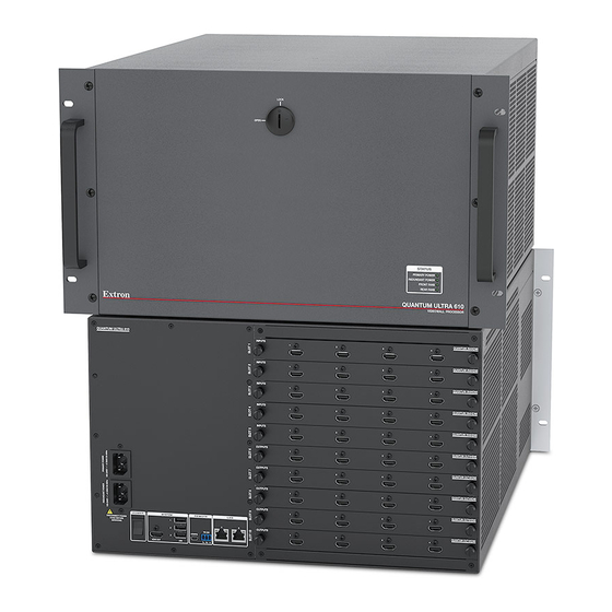
The Extron Quantum Ultra 610 and 305 and Quantum Ultra Connect 128 and 84 Videowall Processors are modular 4K video
processors that support ultra-high resolutions up to 2560x1600 and 4096x2160 (4K) on inputs and outputs. All models provide
customizable output resolutions, input and output image rotation, and mullion compensation for compatibility with most display
technologies. USB, RS-232, and Ethernet interfaces also provide direct connections for control systems.
The Quantum Ultra 610 is a 6U, 10-slot card frame, while the Quantum Ultra 305 is a 3U frame with 5 card slots. These
models support multiple videowalls with mixed resolutions and screen orientations. They also support edge blend compensation,
window border styles, and a variety of source types including picture, RSS, Text, Clock, and VNC. The optional IN SMD 100 input
card decodes and displays multiple simultaneous MPEG2, Motion JPEG, and H.264 video streams at up to 60 frames per second.
Each input card contains four HDMI or two LAN connectors. The output cards contain either four HDMI or four DTP connectors.
Both chassis support any combination of input and output cards. Additional inputs and outputs can be added to a system with
use of one or more additional chassis.
The Quantum Ultra Connect 128 and 84 have fixed configurations. The Quantum Ultra Connect 84 has two HDMI input cards
and one HDMI output card, while the Quantum Ultra Connect 128 has three HDMI input cards and two HDMI output cards.
This card configuration is fixed and cannot be modified by the user.
Control methods for all models include Extron Videowall Configuration Software (VCS), which can be downloaded from the
Extron website
and provides a means of configuring videowall displays and saving window presets. Control is also available via
Simple Instruction Set™ (SIS) commands and by using the Express Mobile Software (EMS) for Quantum Ultra on an iOS, Android,
or Microsoft tablet device.
Rear Panel Features and Connections
Quantum Ultra Rear Panel
NOTE:
Figure 1 shows the rear panel of a Quantum Ultra 610. The Quantum Ultra 305, Connect 84, and Connect 128 have
the same rear panels except that they are 3U high, have fewer card slots, and have no redundant power connector.
Quantum Ultra 610
QUANTUM ULTRA 610
A A A
B B B
POWER
DISCONNECT POWER
CORD BEFORE
SERVICING
C C C
A
Primary AC power connector
B
Redundant AC power connector
C
Power switch
D
HDMI Out system output connector
E
USB system connectors
Figure 1.
Quantum Ultra 610 Rear Panel
Videowall Processor • Setup Guide
®
INPUTS
INPUTS
INPUTS
INPUTS
INPUTS
INPUTS
OUTPUTS
OUTPUTS
OUTPUTS
OUTPUTS
SYSTEM
REMOTE
LAN
OUTPUTS
A
B
RS-232
CONFIG
Tx Rx G
D D D
F F F
G G G
H H H
E E E
(Quantum Ultra 610 only)
LAN A
1
2
3
1
2
3
1
2
3
1
2
3
1
2
3
1
2
3
1
2
3
1
2
3
DTP POWER
SIG
LINK
SIG
LINK
SIG
LINK
OVER TP
OVER TP
12V
4A MAX
Tx Rx
G Tx
Rx
Tx Rx
G Tx
Rx
OUT 1
OUT 2
OUT 3
DTP POWER
SIG
LINK
SIG
LINK
SIG
LINK
OVER TP
OVER TP
12V
4A MAX
Tx Rx
G Tx
Rx
Tx Rx
G Tx
Rx
OUT 1
OUT 2
OUT 3
F
USB Config control connector
G
RS-232 control connector
H
LAN connectors A and B
I
Input and output card slots
QUANTUM IN SMD 100
LAN B
QUANTUM IN4HDMI
4
QUANTUM IN4HDMI
4
QUANTUM IN4HDMI
4
QUANTUM IN4HDMI
QUANTUM IN4HDMI
4
4
QUANTUM OUT4HDMI
4
QUANTUM OUT4HDMI
4
QUANTUM OUT4HDMI
4
QUANTUM OUT4DTP
SIG
LINK
OVER TP
OVER TP
DTP
Tx Rx
G Tx
Rx
Tx Rx
G Tx
Rx
OUT 4
QUANTUM OUT4DTP
SIG
LINK
OVER TP
OVER TP
DTP
Tx Rx
G Tx
Rx
Tx Rx
G Tx
Rx
OUT 4
I I I
1
Advertisement
Table of Contents

Related Manuals for Extron electronics Quantum Ultra Series


Summary of Contents for Extron electronics Quantum Ultra Series
- Page 1 Quantum Ultra Videowall Processor • Setup Guide ® The Extron Quantum Ultra 610 and 305 and Quantum Ultra Connect 128 and 84 Videowall Processors are modular 4K video processors that support ultra-high resolutions up to 2560x1600 and 4096x2160 (4K) on inputs and outputs. All models provide customizable output resolutions, input and output image rotation, and mullion compensation for compatibility with most display technologies.
- Page 2 Quantum Ultra • Setup Guide (Continued) Primary AC power connector — Connect AC power to this IEC connector for the primary power supply. Redundant power connector (Quantum Ultra 610 only) — (Optional) Connect a second AC power source to this IEC connector for the secondary power supply to provide uninterrupted operation in the event of failure of the primary supply.
- Page 3 Open the software program either by double-clicking the VCS icon that is placed on your desktop during installation (shown at right), or by clicking Start > All Programs > Extron Electronics > Videowall Configuration Software. The Extron VCS program opens with the Start screen, Create New Project tab (see figure 2) and a list of devices supported by the current version of VCS.
- Page 4 Quantum Ultra • Setup Guide (Continued) Connection Screen Figure 3. If you do not see your device in the Select Device(s) to Add panel: Click the Manually Add Device button (see figure 3, ). The Manually Add Device window opens (shown at right). In the IP Address field, enter the address of the Quantum to be connected and select the Pull from Hardware radio button.
- Page 5 Product Category Name the Canvas. By default, the first videowall configuration (Canvas) you define is named Canvas 1 (see figure 4, In the Canvas Name field, you can customize the name if desired ( ). Each Canvas that is created (a maximum of 10) is assigned an incremented number that appears in the Canvas ID field and is used in SIS commands.
- Page 6 Quantum Ultra • Setup Guide (Continued) Manual method — Select a Quantum device for a display on the videowall. Click <Undefined> beside the number of the display to be assigned, and select a device from the drop-down menu. Select an output card and slot number for the display. Click <Undefined> in the Output Assignment column, in the row of the display to be assigned.
- Page 7 Product Category Add a source. Click Add (see figure 5, , on the previous page) to add a source of the selected type, or right-click the source type to add and select Add from the pop-up menu. One or more source names are added in the Source Configuration Tree below the source type ( NOTE: The number of sources added depends on the cards installed in your unit.
- Page 8 For information on safety guidelines, regulatory compliances, EMI/EMF compatibility, accessibility, and related topics, see the Extron Safety and Regulatory Compliance Guide on the Extron website. 68-2760-50 Rev. E 06 20 © 2017-2020 Extron Electronics — All rights reserved. All trademarks mentioned are the property of their respective owners. www.extron.com...
Need help?
Do you have a question about the Quantum Ultra Series and is the answer not in the manual?
Questions and answers