
Subscribe to Our Youtube Channel
Related Manuals for Extron electronics QSD 204


Summary of Contents for Extron electronics QSD 204
- Page 1 QSD 204 Quad Standard Decoder series QSD 204 and QSD 204 D 68-651-01 Printed in the USA...
- Page 2 Precautions Safety Instructions • English Warning This symbol is intended to alert the user of important operating and maintenance Power sources • This equipment should be operated only from the power source indicated on the product. This equipment is intended to be used with a main power system with a grounded (servicing) instructions in the literature provided with the equipment.
- Page 3 Install the four rubber feet on the bottom of the procedures, and see chapter three for QSD 204 decoder, or mount the decoder in a rack. programming information. Step 3 Attach input devices to the decoder.
-
Page 4: Main Menu
Quick Start — QSD 204, cont’d QSD 204 Menu System Default Cycle menu 2 sec. 2 sec. INPUT 1 EXTRON Power CMPOSITE QSD204D SIGNAL 2 sec. 2 sec. * The No Signal default menu only occurs if there is no signal present at the currently selected input connector. -
Page 5: Output Configuration Menu
Output Configuration menu Extron QSD204D MENU INPUT CONFIG MENU OUTPUT SIGNAL H SYNC V SERRATION NEXT NEXT NEXT NEXT CONFIG <OFF> Output video types Sync polarity combinations Serration pulse removal • RGB (default) • Off (default) • H-/V- (default) • H+/V- •... - Page 6 Quick Start — QSD 204, cont’d Picture Adjustments menu 2 sec. 2 sec. INPUT 1 EXTRON Power CMPOSITE QSD204D SIGNAL 2 sec. 2 sec. * The No Signal default menu only occurs if there is no signal present at the currently selected input connector.
-
Page 7: Table Of Contents
About this Manual ......................1-2 About the QSD 204 ......................1-2 What is the QSD 204? ....................... 1-2 Controlling the QSD 204 quad standard decoder ............1-2 Features and Options ...................... 1-2 Features ..........................1-2 Options and accessories ....................1-3 Chapter 2 •... - Page 8 Firmware Upgrade Installation ................. A-5 Serial Digital Interface (SDI) Card Installation ..........A-7 68-651-01 Rev. A Printed in the USA 04 02 All trademarks mentioned in this manual are the properties of their respective owners. QSD 204 • Table of Contents...
-
Page 9: Chapter 1 • Introduction
QSD 204 Chapter One Introduction About this Manual About the QSD 204 Features and Options... -
Page 10: About This Manual
What is the QSD 204? The QSD 204 is a high performance quad standard decoder. The QSD 204 comes in two models, one of which offers a serial digital interface (SDI) input connector: QSD 204 (no SDI) and QSD 204 D (with SDI). -
Page 11: Options And Accessories
Windows, or by using a third party control system. Versatile mounting options — The QSD 204 is 1U high, and a half rack wide. It is rack mountable, or it can be placed on a table or other furniture. An optional mounting bracket kit will also allow the QSD to be mounted under a tabletop or desktop. - Page 12 Introduction, cont’d QSD 204 • Introduction...
-
Page 13: Chapter 2 • Installation And Operation
QSD 204 Chapter Two Installation and Operation Mounting the Decoder Rear Panel Features Front Panel Features Menus, Configuration, and Adjustments Image Adjustments Input Reset System Reset Executive Mode IR 901 Infrared Remote Control Troubleshooting... -
Page 14: Mounting The Decoder
If feet were installed on the bottom of the QSD 204, remove them. Place the QSD 204 on one half of the 1U (one unit high) rack shelf (part #60-190-01). Align the front of the QSD 204 with the front of the shelf, and align the threaded holes on the bottom of the QSD 204 with the holes in the rack shelf. -
Page 15: Under-Furniture Mounting
(4) #8 Wood screws Mounting the QSD 204 on the underside of furniture Attach the mounting brackets to the QSD 204 decoder using the decoder’s existing top cover screws. See the above illustration. Place the decoder against the underside of the furniture, then mark the location of the bracket screw holes on the mounting surface. -
Page 16: Application Diagram
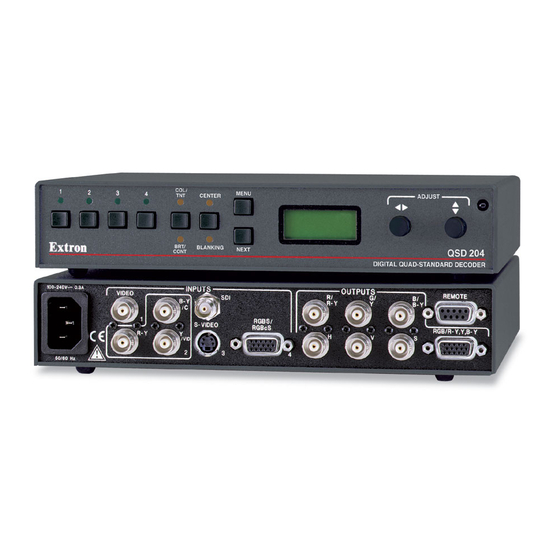
Example application of the QSD 204 Rear Panel Features The rear panel of the QSD 204 D, as shown below, contains all of the possible connectors available on the QSD 204 series of decoders (QSD 204 and QSD 204 D models). - Page 17 SDI (serial digital interface) input connector — Connect an SDI signal to this female BNC connector. Only the QSD 204 D model has an SDI connector. Video input 4: RGBS or RGBcvS — Connect an RGBS or RGBcvS video signal to this 15-pin HD connector.
- Page 18 (pin 5). To force one of the inputs to be always selected, leave the short to logic ground in place. The short overrides front panel input selections. QSD 204 • Installation and Operation...
-
Page 19: Front Panel Features
The front panel buttons, controls, LCD, and infrared sensor of the QSD 204, as shown below, are found on all models of the QSD 204 decoder series. The LEDs above each input button will light green and the LEDs above/below both picture control buttons will light amber when the button is pressed. -
Page 20: Menu Button
Menu button Menu button — Use this button to enter and move through the main menu system in the QSD 204. See the “Menus, Configuration, and Adjustments” section in this chapter for details. Next button Next button —... -
Page 21: Menus, Configuration, And Adjustments
The default menus appear on the LCD when no adjustments are actively being made. They cycle between the screen showing the model of the decoder (QSD 204 or QSD 204 D) and the screen that shows the active input’s number and video format, as shown below. -
Page 22: Input Configuration
MENU MENU Main menus To return to the default screens, let the QSD 204 time-out for 10 seconds, or press the Menu button until the Exit Menu menu appears, then press the Next button. Submenus are accessed from a main menu by pressing the Next button. If you press the Menu button while a submenu is active, the next main menu will become active. -
Page 23: Input 2 Video Type
RGB (default), YUV, or RGsB. Sync Polarity (H Sync V) The display or projector may require a particular combination of horizontal (H) and vertical (V) sync signal polarities. Select the appropriate combination of QSD 204 • Installation and Operation 2-11... -
Page 24: Serration Pulse Removal (Serration)
For CRT output, set the filter “Off”. Use either the Adjust horizontal ( ) or Adjust vertical ( ) knob to specify this mode as “On” or “Off”. The default is “On”. 2-12 QSD 204 • Installation and Operation... -
Page 25: Blue Mode
From this submenu, press the Next button to return to the Default menu cycle, or press the Menu button to return to the Input Configuration menu. EXTRON ADVANCED QSD204D CONFIG MENU MENU INPUT EXIT NEXT CONFIG MENU MENU MENU QSD 204 • Installation and Operation 2-13... -
Page 26: Image Adjustments
Repeat steps 2 and 3 for each image adjustment to be made for that input. The LCD display will indicate that a Tint adjustment is not available (N/A) for Input 2 (component) or Input 4 (RGB, RGBS, RGBcvS). 2-14 QSD 204 • Installation and Operation... -
Page 27: Input Reset
LCD screen. System Reset The QSD 204 can be reset to all of it’s default values by holding down the Input 1 button while simultaneously plugging in the power cord. The System Reset message will be displayed on the LCD screen. -
Page 28: Ir 901 Infrared Remote Control
Executive mode has been enabled on the QSD 204, input selection and adjustments can still be made from the IR 901, but you must use the QSD 204’s front panel or the Windows-based control program (via an RS-232 device) to configure and program the decoder. See chapter three, “Serial Communication”, for details. -
Page 29: Troubleshooting
Troubleshooting This section gives recommendations on what to do if you have problems operating the QSD 204, and it provides examples and descriptions for some image problems you might encounter. The following are some tips to help you in troubleshooting. - Page 30 Installation and Operation, cont’d 2-18 QSD 204 • Installation and Operation...
-
Page 31: Chapter 3 • Serial Communication
QSD 204 Chapter Three Serial Communication RS-232 Programmer’s Guide Control Software for Windows... -
Page 32: Rs-232 Programmer's Guide
When the decoder receives a valid SIS command, it executes the command and sends a response to the host device. If the QSD 204 is unable to execute the command because the command is invalid or it contains invalid parameters, it returns an error response to the host. -
Page 33: Using The Command/Response Tables
= Adjustment range (0 through 127) = Executive mode status (0 through 2) 0 = disabled (executive mode off, normal mode on) 1 = enabled, image adjustments are locked = Blanking adjustment range (0 through 127 lines) QSD 204 • Serial Communication... -
Page 34: Command/Response Table For Sis Commands
Specify the contrast adjustment. Increment Increase the contrast. Decrement Decrease the contrast. View the contrast value Show the contrast setting. Brightness Set a specific value Specify the brightness adjustment. Increment Increase the brightness. Decrement Decrease the brightness. QSD 204 • Serial Communication... - Page 35 Output a “frozen” video image. Disable Frz0 Turn off freeze (output motion). View the freeze status Show the freeze status. Example: Frz0 Executive mode Disable Exe0 Adjustments & selections can be made from the front panel. QSD 204 • Serial Communication...
- Page 36 •Std •Sdi Zap (reset to default settings) Zap image adjustments/controls ZapI Reset the image adjustments to factory settings. Zap all QSD 204 settings/memories zXXX ZapXXX Reset everything: all settings, and adjustments to the factory default. QSD 204 • Serial Communication...
-
Page 37: Command/Response Table For Special Function Sis Commands
Reconstruction filter 0 = off 1 = on (default) Example: 11*1# Fil1 Example: enable the reconstruction filter Serration pulse Serration pulse 0 = off (default) 1 = on Example: 17*1# Ser1 Example: enable serration pulse QSD 204 • Serial Communication... -
Page 38: Control Software For Windows
Follow the instructions that appear on the screen. By default the installation creates a C:\QSD 204 directory, and it places two icons (QSD 204 Control Pgm and QSD 204 Help) into a group or folder named “Extron Electronics”. Using the control program Many items found in the QSD 204 Control Program are also accessible via front panel controls and the LCD menus described in chapter two. -
Page 39: Using The Help Program
Using the help program For information on program features, press the F1 computer key, or click on the Help menu from within the QSD 204 Control Program, or double-click on the QSD 204 Help icon in the Extron Electronics group or folder. - Page 40 Serial Communication, cont’d 3-10 QSD 204 • Serial Communication...
-
Page 41: Appendix A • Appendix
QSD 204 Appendix Appendix Specifications Part Numbers and Accessories Firmware Upgrade Installation Serial Digital Interface (SDI) Card Installation... - Page 42 Serial control pin configurations 1 = input 1 select, 2 = TX, 3 = RX, 4 = input 2 select, 5 = GND, 6 = input 3 select, 7 = input 4 select Contact closure ......9-pin female D connector (same as RS-232 connector) Contact closure pin configurations See pins 1, 4, 6, and 7 above. IR controller module ....IR 901 QSD 204 • Appendix...
- Page 43 Vibration ........ISTA/NSTA 1A in carton (International Safe Transit Association) Listings .......... UL, CUL Compliances ......... CE, FCC Class A, VCCI, AS/NZS, ICES MTBF ..........30,000 hours Warranty ........3 years parts and labor Specifications are subject to change without notice. QSD 204 • Appendix...
-
Page 44: Included Parts
Appendix, cont’d Part Numbers and Accessories Included parts These items are included in each order for a QSD 204 decoder: Included parts Part number QSD 204, 204 D (1) 60-501-01, -02 Rubber feet (self-adhesive) (4) 25-020-02 IEC power cord 27-044-01... -
Page 45: Firmware Upgrade Installation
Some QSD 204 firmware updates must be performed at the Extron factory. Follow these steps to replace firmware in the decoder. Disconnect the AC power cord from the QSD 204 to remove power from the unit. To prevent electric shock or damage, always unplug the QSD 204 decoder from the AC power source before opening the enclosure. - Page 46 Gently, but firmly, press the chip into place in the socket. Replace the top cover on the QSD 204 decoder, and fasten it with the screws that were removed in step 3. Rack/furniture mount the decoder, and reconnect the AC power cord.
-
Page 47: Serial Digital Interface (Sdi) Card Installation
Follow these steps to install an SDI card in the QSD 204. Disconnect the AC power cord from the QSD 204 to remove power from the unit. To prevent electric shock, always unplug the QSD 204 decoder from the AC power source before opening the enclosure. - Page 48 Install the SDI connector’s hex nut and keep the SDI card from twisting as the nut is tightened. Replace the top cover on the QSD 204 decoder, and fasten it with the screws that were removed in step 3. Rack/furniture mount the decoder, and reconnect the AC power cord.
Need help?
Do you have a question about the QSD 204 and is the answer not in the manual?
Questions and answers