Table of Contents
Advertisement
Quick Links
Advertisement
Table of Contents

Related Manuals for AXIOMTEK AIE500-901-FL Series


Summary of Contents for AXIOMTEK AIE500-901-FL Series
- Page 1 AIE500-901-FL Series Embedded System User’s Manual...
-
Page 2: Disclaimers
Axiomtek does not make any commitment to update any information in this manual. Axiomtek reserves the right to change or revise this document and/or product at any time without notice. No part of this document may be reproduced, stored in a retrieval system, or transmitted in any forms or by any means, electronic, mechanical, photocopying, recording, among others, without prior written permissions of Axiomtek Co., Ltd. -
Page 3: Safety Precautions
Safety Precautions Before getting started, please read the following important safety precautions. The AIE500-901-FL does not come with an operating system which must be loaded first before installation of any software into the computer. Be sure to ground yourself to prevent static charge when installing any internal components. -
Page 4: Classification
Classification Degree of production against electric shock: not classified Degree of protection against ingress of water: IP40 Equipment not suitable for use in the presence of a flammable anesthetic mixture with air, oxygen or nitrous oxide. Mode of operation: Continuous 【Note】: All of I/O connectors should be connected with corresponding cables when the system is operating with IP40 rated definition. -
Page 5: General Cleaning Tips
General Cleaning Tips Please keep the following precautions in mind while understanding the details fully before and during any cleaning of the computer and any components within. A piece of dry cloth is ideal to clean the device. Be cautious of any tiny removable components when using a vacuum cleaner to absorb dirt on the floor. -
Page 6: Scrap Computer Recycling
If the computer equipment’s needs the maintenance or are beyond repair, we strongly recommended that you should inform your Axiomtek distributor as soon as possible for the suitable solution. For the computers that are no longer useful or no longer working well, please contact your Axiomtek distributor for recycling and we will make the proper arrangement. -
Page 7: Table Of Contents
Table of Contents Disclaimers ......................ii Safety Precautions ....................iii Classification ......................iv General Cleaning Tips ................... v Scrap Computer Recycling ................... vi CHAPTER 1 INTRODUCTION ............... 1 General Description ................1 System Specifications ............... 2 1.2.1 Product Specification ..................2 1.2.2 I/O System ...................... - Page 8 3.3.17 Reset Button (SW5) ..................30 3.3.18 CMOS Battery Interface (BAT1) ..............30 3.3.19 Power and Storage LED Indicator (LED) ............. 31 CHAPTER 4 JETPACK BSP FLASH METHOD .......... 33 viii...
-
Page 9: Chapter 1 Introduction
AIE500-901-FL Series User’s Manual CHAPTER 1 INTRODUCTION This chapter contains general information and detailed specifications of the AIE500-901-FL. The Chapter 1 includes the following sections: General Description System Specifications Dimensions I/O Outlets Packing List ... -
Page 10: System Specifications
AIE500-901-FL Series User’s Manual Reliable and Stable Design The AIE500-901-FL adopts the advanced fanless system and supporting the NVMe and SATA through M.2 interface, which makes it especially suitable for AI computing environments, best for industrial automation, GPU-accelerated processing and smart city applications. -
Page 11: 1.2.2 I/O System
AIE500-901-FL Series User’s Manual 1.2.2 I/O System One HDMI 2.0 for display (HDMI 2.0 Resolution: up to 4096 x 2160@60Hz) ® ® Two RJ-45 connectors for 10/100/1000 Base-T Ethernet ports (NVIDIA + Intel I210-IT) Two USB 3.1 Gen1 connectors ... -
Page 12: Dimensions
AIE500-901-FL Series User’s Manual Dimensions The following diagrams show you dimensions and outlines of the AIE500-901-FL. 1.3.1 System Dimension Introduction... -
Page 13: Wall Mount Bracket Dimension
AIE500-901-FL Series User’s Manual 1.3.2 Wall mount Bracket Dimension Introduction... -
Page 14: Din-Rail Mount Bracket Dimension
AIE500-901-FL Series User’s Manual 1.3.3 Din-rail mount Bracket Dimension Introduction... -
Page 15: Vesa Arm Mount Bracket Dimension
AIE500-901-FL Series User’s Manual 1.3.4 VESA arm mount Bracket Dimension Introduction... -
Page 16: I/O Outlets
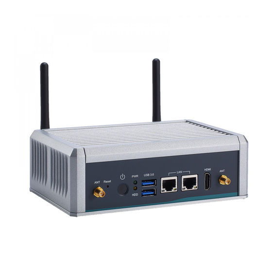
AIE500-901-FL Series User’s Manual I/O Outlets The following figures show you I/O outlets on front view of the AIE500-901-FL. Front View drawing Rear View drawing Introduction... -
Page 17: Packing List
Fanless AI Edge System with NVIDIA® JETSON™ TX2 / TX2i AIE500-901-FL Series SoM, 1 HDMI 2.0, 2 GbE LANs, 2 USB 3.0, 2 COMs and 12 / 24 VDC If you cannot find this package or any items are missing, please contact Axiomtek distributors immediately. Introduction... - Page 18 AIE500-901-FL Series User’s Manual This page is intentionally left blank. Introduction...
-
Page 19: Chapter 2 Hardware Installation
AIE500-901-FL Series User’s Manual CHAPTER 2 HARDWARE INSTALLATION The AIE500-901-FL is convenient for your various hardware configurations, such as SSD (Solid State Drive) and PCI Express Mini Card modules. The chapter 2 will show you how to install the hardware. - Page 20 AIE500-901-FL Series User’s Manual Step 4 Holding the PCI Express mini card at a 45 degree angle up from horizontal, slowly insert the golden fingers into the PCI Express slot until it is fully inserted in. Step 5 Press it down gently, but firmly, and then secure the PCI Express mini card to the carrier by tightening up the one M2*5L Phillips pan head screw to the marked position.
-
Page 21: Installing Lte And Extra Wi-Fi Antenna Cable
AIE500-901-FL Series User’s Manual Installing LTE and extra Wi-Fi Antenna Cable Step 1 Install the Mini PCIe card into the Mini PCIe slot and affix it with a screw. For more details, please refer to section 2.1: Installing the PCI Express Mini Card. - Page 22 AIE500-901-FL Series User’s Manual Step 3 Install the antenna cable connector through the opening at the front of the chassis. Step 4 Put the washer and Hex nut into the antenna cable connector, and tighten it up. Hardware Installation...
- Page 23 AIE500-901-FL Series User’s Manual Step 5 Connect the antenna cable to the PCI Express mini card. Hardware Installation...
-
Page 24: Installing The M.2 2280 Key M Ssd Module
AIE500-901-FL Series User’s Manual Installing the M.2 2280 Key M SSD Module Step 1 Turn off the system, and unplug the power adaptor. Step 2 Turn the system upside down to locate screws at the bottom side as red marked and loosen four screws. - Page 25 AIE500-901-FL Series User’s Manual Step 4 Holding the M.2 2280 Key M SSD card at a 30 degree angle up from horizontal, slowly insert the golden fingers into the M.2 2280 Key M slot until it is fully inserted in.
- Page 26 AIE500-901-FL Series User’s Manual This page is intentionally left blank. Hardware Installation...
-
Page 27: Chapter 3 Jumper Setting & Connector
AIE500-901-FL Series User’s Manual CHAPTER 3 JUMPER SETTING & CONNECTOR Proper jumper settings configure the AIE500-901-FL to meet your application purpose. We are here with listing a summary table of all jumpers and default settings for onboard devices, respectively. Jumper & Connector Location SBC87901 Top View Jumper setting &... - Page 28 AIE500-901-FL Series User’s Manual SBC87901 Bottom View Note: We strongly recommended that you should not modify any unmentioned jumper setting without Axiomtek FAE’s instruction. Any modification without instruction might cause system to become damage. Jumper setting & connector...
-
Page 29: Jumper Setting Summary
AIE500-901-FL Series User’s Manual Jumper Setting Summary Proper jumper settings configure the AIE500-901-FL to meet your application purpose. We are herewith listing a summary table of all jumpers and default settings for onboard devices, respectively. SBC87901: Settings Jumper Functions Port 1... -
Page 30: Connectors
Connectors connect the board with other parts of the system. Loose or improper connection might cause problems. Make sure all connectors are properly and firmly connected. Here is a summary table shows you all connectors and button on the AIE500-901-FL Series. PCB Location... -
Page 31: Micro Usb 2.0 Connector (Otg) (Cn1)
AIE500-901-FL Series User’s Manual 3.3.1 Micro USB 2.0 Connector (OTG) (CN1) The CN1 is specifically designed for image flashing only. To flash Jetpack, please switching SW1 to ON before booting up the system, which would force the system to recovery mode. -
Page 32: Dc-In Connector (Cn6)
AIE500-901-FL Series User’s Manual 3.3.4 DC-in Connector (CN6) The system reserves an onboard wide range DC-in connector (CN6) for system power 12VDC or 24VDC input. Signal DCIN 3.3.5 PCI-Express Mini Card Connector (CN7) The AIE500-901-FL supports a full-size PCI-Express Mini Card slots. CN7 is applying to either PCI-Express or USB 2.0 signal, and complies with PCI-Express Mini Card Spec. -
Page 33: Sim Card Slot (Cn8)
AIE500-901-FL Series User’s Manual 3.3.6 SIM Card Slot (CN8) AIE500-901-FL comes with SIM Card Slot (CN8) for inserting SIM Card. In order to work properly, the SIM Card must be used together with 3G/LTE module which would be inserted to PCI-Express Mini Card Connector (CN7). It is mainly used for 3G/LTE wireless network application. -
Page 34: 2280 Key M Pcie X1 And Sata Ssd (Cn10)
AIE500-901-FL Series User’s Manual 3.3.7 M.2 2280 Key M PCIe x1 and SATA SSD (CN10) The AIE500-901-FL comes with one M.2 2280 Key M PCIe x1 and SATA SSD for storage. Signal Signal Signal Signal +3.3V +3.3V LED_1# +3.3V +3.3V +3.3V... -
Page 35: Hdmi Connector (Cn12)
AIE500-901-FL Series User’s Manual 3.3.8 HDMI Connector (CN12) The HDMI (High-Definition Multimedia Interface) is a compact digital interface which is capable of transmitting high-definition video and high-resolution audio over a single cable. Signal Signal HDMI1_DATA2+ HDMI1_DATA2- HDMI1_DATA1+ HDMI1_DATA1- HDMI1_DATA0+ HDMI1_DATA0-... -
Page 36: Digital I/O Connector (Cn14) (Optional)
AIE500-901-FL Series User’s Manual 3.3.10 Digital I/O Connector (CN14) (Optional) The AIE500-901-FL supports one 8-Channel digital I/O connector by option. The digital I/O is controlled via software programming. Signal Signal DIO01 DIO08 DIO02 DIO07 DIO03 DIO06 DIO04 DIO05 3.3.11 Ethernet Ports (LAN1, LAN2) ®... -
Page 37: Serial & Can Port Connector (Com / Can 1, Com / Can 2)
AIE500-901-FL Series User’s Manual 3.3.12 Serial & CAN Port Connector (COM / CAN 1, COM / CAN 2) This system supports two serial ports or two CAN-bus ports or one serial port and one CAN- bus port, which are shared by the same DB9 ports. User could select either COM or CAN-bus by jumper setting, JP1 and JP2. -
Page 38: At/Atx Switch (Sw3)
AIE500-901-FL Series User’s Manual 3.3.15 AT/ATX Switch (SW3) If you turn ON the Pin 8(AT mode) of SW3, the system will be automatically power on without pressing soft power button during power input; we can use this switch to achieve auto power on demand. -
Page 39: Power And Storage Led Indicator (Led)
AIE500-901-FL Series User’s Manual 3.3.19 Power and Storage LED Indicator (LED) The Yellow LED is linked to Solid-state Drive (SSD) activity signal. LED flashes every time SSD is accessed. The power LED (Green) lights up and will remain steady while the system is powered on. - Page 40 AIE500-901-FL Series User’s Manual This page is intentionally left blank. Jumper setting & connector...
-
Page 41: Chapter 4 Jetpack Bsp Flash Method
3.3.11 Recovery Mode Switch (SW 1). Connect an HDMI monitor to AIE500-901-FL. Step2. Please prepare your image file from Axiomtek or download it from FTP. Untar the files and assemble the root file system with the command below: sudo tar xpf imagefilename 【Note】: Please type your full image name instead of imagefilename Step3.
Need help?
Do you have a question about the AIE500-901-FL Series and is the answer not in the manual?
Questions and answers