Table of Contents
Advertisement
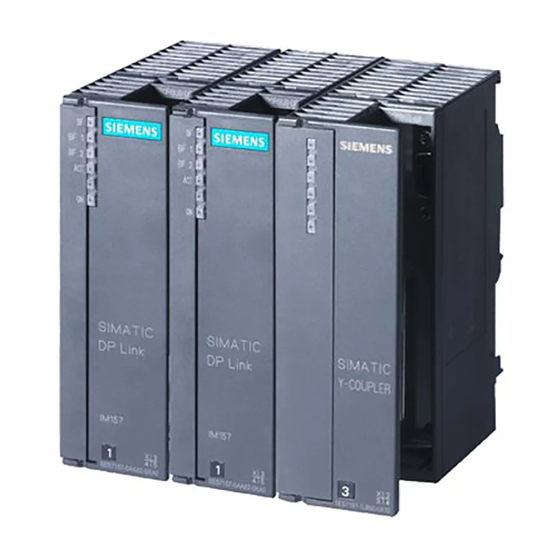
SIMATIC
DP/PA Link and Y Link
Bus Couplings
Manual
This manual has the order number:
6ES7157-0AA00-8BA0
Edition 12/2002
A5E00193841-01 1
Preface, Contents
Product Overview
Description of Components
Installation
Wiring
Commissioning the DP/PA
Coupler for Stand-Alone
Operation
Commissioning the DP/PA Link
Commissioning the Y Link
Operation of the DP/PA Link and
the Y Link
Diagnostics Using LEDs
Diagnostics Using the User
Program
Appendices
Fundamentals of PROFIBUS-PA
Technical Specifications
DP Slaves Connectable to a
Y Link
Order Numbers and Accessories
Glossary, Index
1
2
3
4
5
6
7
8
9
10
A
B
C
D
Advertisement
Table of Contents


Need help?
Do you have a question about the Simatic 6ES7 157-0AD81-0 A0 Series and is the answer not in the manual?
Questions and answers