Table of Contents
Advertisement
Quick Links
SIMATIC NET
Industrial Wireless LAN
SCALANCE W786-x
Operating Instructions
12/2021
A5E03678337-14
Introduction
Safety notices
Security recommendations
Description
Installation and removal
Connecting up
Maintenance and cleaning
Error correction
Technical specifications
Dimension drawings
Certification
1
2
3
4
5
6
7
8
9
10
11
Advertisement
Table of Contents

Related Manuals for Siemens SIMATIC NET SCALANCE W786 Series


Summary of Contents for Siemens SIMATIC NET SCALANCE W786 Series
- Page 1 Introduction Safety notices Security recommendations SIMATIC NET Description Industrial Wireless LAN SCALANCE W786-x Installation and removal Connecting up Operating Instructions Maintenance and cleaning Error correction Technical specifications Dimension drawings Certification 12/2021 A5E03678337-14...
- Page 2 Note the following: WARNING Siemens products may only be used for the applications described in the catalog and in the relevant technical documentation. If products and components from other manufacturers are used, these must be recommended or approved by Siemens. Proper transport, storage, installation, assembly, commissioning, operation and maintenance are required to ensure that the products operate safely and without any problems.
-
Page 3: Table Of Contents
Table of contents Introduction ............................5 Safety notices ............................9 Security recommendations........................11 Description............................17 Device view ........................17 Structure of the type designations..................18 Scope of delivery ....................... 18 Accessories ........................18 4.4.1 Installation ........................19 4.4.2 Plug........................... 19 4.4.3 Flexible connecting cables, antennas and accessories ............ - Page 4 Table of contents Connecting Industrial Ethernet................... 61 SFP/SFP+ transceivers......................62 Maintenance and cleaning ........................65 Error correction............................ 67 Device configuration with PRESET-PLUG................67 Restoring the factory settings..................... 69 Firmware update via WBM or CLI not possible ..............70 Technical specifications ........................73 SCALANCE W786-1 ......................
-
Page 5: Introduction
Make sure that you read the explanations and instructions in the README.txt file Documentation on the Internet You can find the current version of the document on the Internet at (https:// support.industry.siemens.com/cs/de/en/ps/15859/man) Enter the name or article number of the product in the search filter. SCALANCE W786-x Operating Instructions, 12/2021, A5E03678337-14... - Page 6 To stay informed about product updates, subscribe to the Siemens Industrial Security RSS Feed under https://www.siemens.com/industrialsecurity (https://www.siemens.com/industrialsecurity). Firmware The firmware is signed and encrypted. This ensures that only firmware created by Siemens can be downloaded to the device. The firmware is available on the Internet pages of the Siemens Industry Online Support: (https:// support.industry.siemens.com/cs/de/en/view/109802059)
- Page 7 This means that Siemens only monitors the current firmware/software version for security vulnerabilities. Device defective If a fault develops, send the device to your SIEMENS representative for repair. Repairs on-site are not possible. Decommissioning Shut down the device properly to prevent unauthorized persons from accessing confidential data in the device memory.
- Page 8 Introduction SCALANCE W786-x Operating Instructions, 12/2021, A5E03678337-14...
-
Page 9: Safety Notices
Safety notices CAUTION To prevent injury, read the manual before use. Read the safety notices Note the following safety notices. These relate to the entire working life of the device. You should also read the safety notices relating to handling in the individual sections, particularly in the sections "Installation"... - Page 10 Safety notices SCALANCE W786-x Operating Instructions, 12/2021, A5E03678337-14...
-
Page 11: Security Recommendations
OpenVPN). • Separate connections correctly (WBM, Telnet, SSH etc.). • Check the user documentation of other Siemens products that are used together with the device for additional security recommendations. • Using remote logging, ensure that the system protocols are forwarded to a central logging server. - Page 12 • Verify certificates based on the fingerprint on the server and client side to prevent "man in the middle" attacks. Use a second, secure transmission path for this. • Before sending the device to Siemens for repair, replace the current certificates and keys with temporary disposable certificates and keys, which can be destroyed when the device is returned.
- Page 13 Information Disclosure Vulnerability (for example, BEAST). • Ensure that the latest firmware version is installed, including all security-related patches. You can find the latest information on security patches for Siemens products at the Industrial Security (https://www.siemens.com/industrialsecurity) or ProductCERT Security Advisories (https://www.siemens.com/cert/en/cert-security-advisories.htm) website.
- Page 14 Security recommendations • Configuration files can be downloaded from the device. Ensure that configuration files are adequately protected. The options for achieving this include digitally signing and encrypting the files, storing them in a secure location, or transmitting configuration files only through secure communication channels.
- Page 15 Security recommendations • The following protocols provide secure alternatives: – SNMPv1/v2c → SNMPv3 Check whether use of SNMPv1/v2c is necessary. SNMPv1/v2c is classified as non-secure. Use the option of preventing write access. The product provides you with suitable setting options. If SNMP is enabled, change the community names.
- Page 16 Security recommendations Service Protocol/port Default port Configurable Authentication Encryption number status Port Service HTTPS TCP/443 Open ✓ ✓ ✓ ✓ NTP Client UDP/123 Outgoing only ✓ ✓ PROFINET UDP/34964 Open ✓ UDP/49154 UDP/49155 RADIUS UDP/1812 Closed ✓ ✓ ✓ Remote Capture TCP/2002 Closed ✓...
-
Page 17: Description
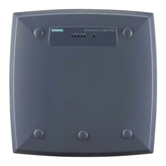
Description Device view ① Power supply connection / supply adapter ② Ethernet port ③ LED display ④ Antenna connectors R1A1, R1A2, R1A3 ⑤ Antenna connectors R2A1, R2A2, R2A3 (only devices with two IWLAN interfaces) ⑥ Reset button ⑦ Cable feedthrough ⑧... -
Page 18: Structure Of The Type Designations
The mounting set with the holding plate does not ship with the device, see Accessories (Page 19). Please check that the consignment you have received is complete. If the consignment is incomplete, contact your supplier or your local Siemens office. Accessories Technical data subject to change. -
Page 19: Installation
Description 4.4 Accessories You will find further information on the range of accessories in the Industry Mall (https:// mall.industry.siemens.com) 4.4.1 Installation Mounting set Component Description Article number Mounting set Mounting set can only be used in conjunction with SCA‐ 6GK5798-8MG00-0AA0 LANCE W-786;... -
Page 20: Flexible Connecting Cables
Description 4.4 Accessories 4.4.3.1 Flexible connecting cables Flexible connecting cable N-Connect/R-SMA Flexible connecting cable for connecting an antenna to a SCALANCE W device with R-SMA connectors, preassembled with a connector N-male and R-SMA male Length Article number 0.3 m 6XV1875-5CE30 6XV1875-5CH10 6XV1875-5CH20 6XV1875-5CH50... -
Page 21: Lightning Protection
Description 4.4 Accessories Flexible connecting cable IWLAN QMA/N-Connect male/female Adapter cable for connecting a MIMO antenna with QMA connectors with the flexible connecting cables. Preassembled with two connectors QMA male and N-Connect female. pack of 3 Length Article number 6XV1875-5JH10 For railway applications, the following connecting cable is available Note: Scope of delivery: Pack of 1 Length... - Page 22 Description 4.4 Accessories Type Properties Article number IWLAN RCoax RCoax helical antenna with circular polariza‐ 6GK5792-4DN00-0AA6 tion for RCoax systems, 4 Bi, 2.4 GHz, IP65, N- ANT792-4DN Connector female. ANT792-6MN Omnidirectional antenna, mast/wall mount‐ 6GK5792-6MN00-0AA6 ing, 6 dBi 2.4 GHz, IP67, N-Connect female ANT792-8DN Directional antenna, mast/wall mounting, 6GK5792-8DN00-0AA6...
- Page 23 Description 4.4 Accessories Type Properties Article number IWLAN RCoax Cable 2,4 Omnidirectional antenna, 0 Bi 2.400 6XV1875-2A GHz PE 1/2" -2.485 GHz, N-Connect female IWLAN RCoax Cable Omnidirectional antenna, 0 Bi 5.150 6XV1875-2D 5 GHz PE 1/2" -5.875 GHz, N-Connect female NOTICE ANT795-4MA The ANT795-4MA antenna has degree of protection IP30 and is therefore only suitable for dry...
-
Page 24: Led Display
Description 4.5 LED display LED display Information on operating status and data transfer On the front of the housing, several LEDs provide information on the operating status of the SCALANCE W786: SCALANCE W786-1 Color Meaning Power supply L1 too low. Green Power supply via a power supply adapter or direct supply 24 V DC. - Page 25 Description 4.5 LED display Color Meaning There is no connection over the Ethernet port P2. Green There is no connection over the Ethernet port P2. (Link) Flashing green Data transfer over the Ethernet interface P2. and yellow The WLAN interface 1 is deactivated. Green Access point mode: The WLAN interface 1 is initialized and ready for operation.
- Page 26 Description 4.5 LED display Color Meaning The WLAN interface 2 is deactivated. Client mode: The LED is always off because WLAN interface 2 is not available in client mode. Green Access point mode: The WLAN interface 2 is initialized and ready for operation. Flashing green Access point mode: and yellow...
-
Page 27: Reset Button
Description 4.6 Reset button Note Primary user (radar) on all enabled channels (only when DFS is enabled) If the device detects competing radar signals on all enabled channels of the WLAN interface, the F LED is lit and R1/R2 flash. No data traffic is then possible for the next 30 minutes. After this time, the device runs the scan again and checks whether a primary user still exists. - Page 28 Description 4.6 Reset button Functions The reset button has the following functions: • Restart of the device To restart the device, press the Reset button briefly. Note If you make changes to the configuration and restart immediately afterwards with the reset button, the changes may be lost.
-
Page 29: Installation And Removal
Installation and removal Safety notices for installation Safety notices When installing the device, keep to the safety notices listed below. NOTICE Improper mounting Improper mounting may damage the device or impair its operation. • Before mounting the device, always ensure that there is no visible damage to the device. •... - Page 30 Installation and removal 5.1 Safety notices for installation WARNING If a device is operated in an ambient temperature of more than 40 °C, the temperature of the device housing may be higher than 70 °C. The device must therefore be installed so that it is only accessible to service personnel or users that are aware of the reason for restricted access and the required safety measures at an ambient temperature higher than 40 ℃.
- Page 31 Installation and removal 5.1 Safety notices for installation WARNING To comply with EU Directive 2014/34 EU (ATEX 114), UK-Regulation SI 2016/1107 or the conditions of IECEx or CCC-Ex, the housing or cabinet must meet the requirements of at least IP54 (according to EN/IEC 60529, GB/T 4208) in compliance with EN IEC/IEC 60079‑7, GB 3836.8.
-
Page 32: Removing/Installing The Housing Cover
Installation and removal 5.2 Removing/installing the housing cover Removing/installing the housing cover When does the housing cover need to be removed? You can only perform the following activities when the cover is removed. • You want to screw the SCALANCE W786 to a wall or onto the optional mounting plate. •... - Page 33 Installation and removal 5.2 Removing/installing the housing cover P o E Figure 5-1 Removing the coverA Sealing capB Cover screwC Housing cover Follow the steps below to remove the housing cover: 1. Remove the sealing caps from the housing cover (position A in the figure above) 2.
-
Page 34: Installing Cables
Installation and removal 5.3 Installing cables Installing cables Connecting up cables prior to mounting Before you screw a SCALANCE W786 to a wall or to the optional mounting plate, the cables for the power supply, for Ethernet, and, when necessary, for the external antennas must be connected up first. -
Page 35: Wall Mounting
Installation and removal 5.4 Wall mounting Figure 5-3 Grounding connector on the rear of the SCALANCE W786 Wall mounting Drilling template Note Installation location The following should be noted with regard to the installation location: • Devices with an internal antenna must be aligned according to the characteristics of the internal antenna (refer to the technical specifications of the antenna -->... - Page 36 Installation and removal 5.4 Wall mounting Figure 5-4 Drilling template for wall mounting of the SCALANCE W786 Procedure Figure 5-5 SCALANCE W786 wall mounting SCALANCE W786-x Operating Instructions, 12/2021, A5E03678337-14...
-
Page 37: Mounting With Mounting Plate
Installation and removal 5.5 Mounting with mounting plate Follow the steps below to screw a SCALANCE W786 to a wall: 1. Lead the cables into the housing of the SCALANCE W786 (position A in the figure above). Note the information in the section "Connecting up cables". 2. - Page 38 Installation and removal 5.5 Mounting with mounting plate Figure 5-6 Drilling template for fitting the mounting plate to a wall SCALANCE W786-x Operating Instructions, 12/2021, A5E03678337-14...
- Page 39 Installation and removal 5.5 Mounting with mounting plate Procedure Secure the mounting plate to the wall with four screws. The screws are not supplied with the device. The type and length of the screws depend on the type of wall. Type of screw: •...
-
Page 40: Screw Cable Inlet On The Mounting Plate
Installation and removal 5.5 Mounting with mounting plate 5.5.2 Screw cable inlet on the mounting plate Protection of the cable feedthrough against strong water jets The cabling of a SCALANCE W786 is led out of the rear of the device. The housing seal is effective only when it is not subjected to water jets. -
Page 41: Installing Mounting Plate On An S7-300 Standard Rail
Installation and removal 5.5 Mounting with mounting plate To screw the cover plate for the cable feedthrough to the mounting plate, follow the steps below: 1. Fit the cover plate on the mounting plate from below until the two lugs (position A in the figure above) engage the lower edge of the mounting plate. -
Page 42: Installing Mounting Plate On A Din Rail
Installation and removal 5.5 Mounting with mounting plate 5.5.4 Installing mounting plate on a DIN rail Procedure Figure 5-10 Mounting plate with fittings for DIN rail mounting Follow the steps below to fit the mounting plate to a DIN rail: 1. -
Page 43: Installing Mounting Plate On The Mast
Installation and removal 5.5 Mounting with mounting plate 5.5.5 Installing mounting plate on the mast Procedure Figure 5-11 Holding plate with hose clips for mast mounting Follow the steps below to fit the holding plate to a mast: 1. Guide the hose clips through the slots of the holding plate (position A in the figure above). 2. -
Page 44: Mounting Device On The Mounting Plate
Installation and removal 5.5 Mounting with mounting plate 5.5.6 Mounting device on the mounting plate Procedure for mounting the device Figure 5-12 Fitting the SCALANCE W786 to a mounting plate Follow the steps below to fit a SCALANCE W786 to a mounting plate: 1. - Page 45 Installation and removal 5.5 Mounting with mounting plate 3. Push in the SCALANCE W786 until it engages in the notches at the lower edge of the mounting plate (position C in the figure above). Figure 5-13 Screwing a SCALANCE W786 to a mounting plate 4.
- Page 46 Installation and removal 5.5 Mounting with mounting plate SCALANCE W786-x Operating Instructions, 12/2021, A5E03678337-14...
-
Page 47: Connecting Up
Connecting up Safety when connecting up Safety notices When connecting up the device, keep to the safety notices listed below. WARNING Danger from line voltage After removing the housing cover, there is a risk of touching live parts in the area of the connecting terminals of the power supply adapter. - Page 48 Connecting up 6.1 Safety when connecting up Note The requirements of EN61000-4-5, surge immunity tests on power supply lines, are met only when a Blitzductor is used with 12 to 24 VDC: BVT AVD 24 article number: 918 422 Manufacturer: DEHN+SÖHNE GmbH+Co.KG, Hans Dehn Str. 1, Postfach 1640, D - 92306 Neumarkt, Germany Safety extra low voltage WARNING...
- Page 49 Connecting up 6.1 Safety when connecting up NOTICE Damage to the device due to potential differences To fully eliminate the influence of electromagnetic interference, the device must be grounded. There must be no potential difference between the following parts, otherwise the device or other connected device could be severely damaged: •...
- Page 50 Connecting up 6.1 Safety when connecting up WARNING EXPLOSION HAZARD Do not press the reset button if there is a potentially explosive atmosphere. WARNING Unsuitable cables or connectors Risk of explosion in hazardous areas • Only use connectors that meet the requirements of the relevant type of protection. •...
- Page 51 Connecting up 6.1 Safety when connecting up WARNING Insufficient isolation of intrinsically safe and non-intrinsically safe circuits Risk of explosion in hazardous areas • When connecting intrinsically safe and non-intrinsically safe circuits, ensure that the galvanic isolation is performed properly in compliance with local regulations (e.g. IEC 60079-14).
- Page 52 Connecting up 6.1 Safety when connecting up WARNING Restricted area of application This equipment is suitable for use in Class I, Division 2, Groups A, B, C and D or non-hazardous locations only. WARNING Restricted area of application This equipment is suitable for use in Class I, Zone 2, Group IIC or non-hazardous locations only. WARNING - Cat.
-
Page 53: Cables For Power Supply And Ethernet
Connecting up 6.2 Cables for power supply and Ethernet Cables for power supply and Ethernet Cable specification The following table lists the requirements for a cable depending on the use case. Application Specification Direct 24 V DC supply • Round cable cross-section with 6 to 8 mm diameter. -
Page 54: Connecting The Cables
Connecting up 6.3 Connecting the cables WARNING Only use cables suitable for high temperatures! If temperatures in excess of 70 °C occur on the cable or at the housing socket, or the temperature at the branching points of the cables exceeds 80 °C, special measures need to be taken. - Page 55 Connecting up 6.3 Connecting the cables Figure 6-1 Connecting a cable and fitting the strain relief clamps Follow the steps below to connect cables to the SCALANCE W786: 1. Connect the cables to the appropriate contacts. (Position A in the figure above) You have the following options: –...
-
Page 56: Connecting The Power Supply
Connecting up 6.4 Connecting the power supply 3. Press the strain relief clamp into the housing until the cable is located completely in the opening in the housing seal (position C in the figure above). 4. Seal all openings not required for cables with sealing plugs (position D in the figure above). 5. - Page 57 Connecting up 6.4 Connecting the power supply Power over Ethernet (PoE) With the SCALANCE W786-x RJ-45, power supply using Power over Ethernet (PoE) is also possible. The devices support the standards 802.3at type 1 (IEEE 802.3af) and IEEE 802.3at type 2.
-
Page 58: Connecting The Power Supply Adapter
Connecting up 6.5 Connecting the power supply adapter Figure 6-4 Position of the connector when inserted in the socket of the housing Note Grounding connector The device has a grounding connector on the back of the device. You need to mount the grounding connector before securing the device. - Page 59 Connecting up 6.5 Connecting the power supply adapter WARNING Danger from line voltage Only electrical specialists may open the device and connect the power supply adapter. Connect or disconnect power supply cables only when the power is turned off. Start the SCALANCE W786 only when you have screwed down the housing cover again so that there is once again protection against touching live parts.
- Page 60 Connecting up 6.5 Connecting the power supply adapter How to fit a power supply adapter The following figure shows how a power supply adapter is fitted: 12 - 24 V 110 - 230 V L1 M1 M2 L2 Securing screw Pull-out loop Figure 6-5 Fitting a power supply adapter...
-
Page 61: Connecting Industrial Ethernet
Connecting up 6.6 Connecting Industrial Ethernet How to remove the power supply adapter NOTICE With careless disassembly the connector can break off Use only the dismantling loop (position B) if you take the power supply adapter out of the SCALANCE W786. This prevents the connector skewing on the back of the power supply adapter and breaking off. -
Page 62: Sfp/Sfp+ Transceivers
Connecting up 6.7 SFP/SFP+ transceivers Device variant W786-x RJ-45 Follow the steps below to connect an Ethernet cable to a SCALANCE W786 with an RJ-45 jack: 1. Insert the RJ-45 plug of the Ethernet cable in the jack of the SCALANCE W786-x RJ-45. 2. - Page 63 NOTICE Use only approved SFP transceivers If you use SFPs not approved by Siemens AG, Siemens cannot accept any responsibility for the correct functioning of the device according to the specification. If components are used that have not been Siemens approved, Siemens cannot vouch for their compatibility or for risk-free use of these components.
- Page 64 Connecting up 6.7 SFP/SFP+ transceivers Position of the SFP slots The SFP slots are located below the housing cover to the left of the antenna sockets. Figure 6-7 Position of the SFP slots below the housing cover SCALANCE W786-x Operating Instructions, 12/2021, A5E03678337-14...
-
Page 65: Maintenance And Cleaning
Maintenance and cleaning WARNING Unauthorized repair of devices in explosion-proof design Risk of explosion in hazardous areas • Repair work may only be performed by personnel authorized by Siemens. WARNING Impermissible accessories and spare parts Risk of explosion in hazardous areas •... - Page 66 Maintenance and cleaning SCALANCE W786-x Operating Instructions, 12/2021, A5E03678337-14...
-
Page 67: Error Correction
Error correction Device configuration with PRESET-PLUG Note the additional information and security notes in the operating instructions of your device. NOTICE Do not remove or insert a PLUG during operation A PLUG may only be removed or inserted when the device is turned off. Note Support as of V6.0 The PRESET-PLUG functionality is supported as of firmware version V6.0. - Page 68 Error correction 8.1 Device configuration with PRESET-PLUG 4. Create the PRESET-PLUG with the "presetplug" command. The firmware version of the device and the current device configuration incl. user accounts and certificates are stored on the PLUG and the PLUG is then write protected. 5.
-
Page 69: Restoring The Factory Settings
Error correction 8.2 Restoring the factory settings Formatting a PRESET-PLUG (resetting the preset function) You format the PRESET PLUG using the Command Line Interface (CLI) to reset the preset function. To do this, follow the steps outlined below: 1. Start the remote configuration using Telnet (CLI) and log on with a user with the "admin" role. 2. -
Page 70: Firmware Update Via Wbm Or Cli Not Possible
Error correction 8.3 Firmware update via WBM or CLI not possible With SINEC PNI Follow the steps below to reset the device parameters to the factory settings with the SINEC PNI: 1. Select the device whose parameters you want to reset. 2. - Page 71 Error correction 8.3 Firmware update via WBM or CLI not possible Note Use of CLI and TFTP in Windows 10 If you want to access the CLI or TFTP in Windows 10, make sure that the relevant functions are enabled in Windows 10. Result The firmware is transferred to the device.
- Page 72 Error correction 8.3 Firmware update via WBM or CLI not possible SCALANCE W786-x Operating Instructions, 12/2021, A5E03678337-14...
-
Page 73: Technical Specifications
Technical specifications SCALANCE W786-1 The following technical specifications apply to the following devices: • SCALANCE W786‑1 RJ45 Note You will find detailed information on the transmit power and receiver sensitivity in the document "Leistungsdaten 802.11abgn PCIe Minicard / Characteristics 802.11abgn PCIe Minicard" (REF_W700-RadioInterface.pdf). - Page 74 Technical specifications 9.1 SCALANCE W786-1 Technical specifications Wireless interface IWLAN interface Quantity Antenna connector Quantity Design R-SMA female Impedance 50 Ω nominal Frequency range 2412 ... 2480 MHz 4920 ... 5875 MHz Electrical data Direct 24 VDC supply Supply voltage from terminal block/ 24 VDC Safety Extra Low Voltage (SELV) socket Permitted range...
-
Page 75: Scalance W786-2
Technical specifications 9.2 SCALANCE W786-2 Technical specifications Weight Without power supply adapter 2.24 kg With power supply adapter 12 - 24 VDC 2.4 kg With power supply adapter 100 ... 2.4 kg 240 VAC Installation options Direct Wall mounting With additional holding plate Mast mounting •... - Page 76 Technical specifications 9.2 SCALANCE W786-2 Technical specifications RJ-45 variants Quantity Design RJ-45 jack Properties Half duplex/full duplex, autocrossover, auto‐ negotiation, autosensing, PoE, floating SFP variants Quantity Design Pluggable transceiver slots Properties Half duplex/full duplex, autocrossover, auto‐ negotiation, autosensing, PoE, floating Permitted cable lengths (Ethernet) (Alternative combinations per length range)
- Page 77 Technical specifications 9.2 SCALANCE W786-2 Technical specifications Power supply via optional power sup‐ 12 to 24 VDC (9.6 to 28.8 VDC) ply adapter 100 to 240 VAC Fusing 2.5 A / 24 VDC 1 A / 48 VDC PoE Current consumption At 12 ...
-
Page 78: Field Diagrams Of Internal Antennas Scalance W786-2Ia
Technical specifications 9.3 Field diagrams of internal antennas SCALANCE W786‑2IA Field diagrams of internal antennas SCALANCE W786‑2IA Horizontal radiation pattern 2500 MHz -150 -120 SCALANCE W786-x Operating Instructions, 12/2021, A5E03678337-14... - Page 79 Technical specifications 9.3 Field diagrams of internal antennas SCALANCE W786‑2IA Vertical radiation pattern 2500 MHz -150 -120 Horizontal radiation pattern 5800 MHz -150 -120 SCALANCE W786-x Operating Instructions, 12/2021, A5E03678337-14...
- Page 80 Technical specifications 9.3 Field diagrams of internal antennas SCALANCE W786‑2IA Vertical radiation pattern 5800 MHz -150 -120 SCALANCE W786-x Operating Instructions, 12/2021, A5E03678337-14...
-
Page 81: Dimension Drawings
Dimension drawings Front view and view from above of the SCALANCE W786 SCALANCE W700 P1 R1 R2 R3 SCALANCE W786-x Operating Instructions, 12/2021, A5E03678337-14... - Page 82 Dimension drawings SCALANCE W786-x Operating Instructions, 12/2021, A5E03678337-14...
-
Page 83: Certification
Certification You will find the approvals of the products in the reference work "Approvals SCALANCE W700 802.11n" on the Internet pages of Siemens Industry Online Support: • Using the search function at Siemens Industry Online Support (https:// support.industry.siemens.com/cs/de/en/view/109476834) • Using the search function at Industrial communication (https:// support.industry.siemens.com/cs/ww/en/ps/15859/cert) - Page 84 Certification SCALANCE W786-x Operating Instructions, 12/2021, A5E03678337-14...
-
Page 85: Index
Index Antenna cables, 20 Installation, 35 Antennas, 20 Interfaces, 73, 74, 75, 76, 77 Directional antenna, 22 Dual directional antenna with linear polarization, 22 Dual-band directional antenna with linear LED display, 24 polarization, 22 Lightning protection, 47 Helical antenna, 22 Loading firmware, 28 MIMO antenna, 22 Omnidirectional antenna, 22... - Page 86 Index Wall mounting direct, 35 with mounting plate, 37 SCALANCE W786-x Operating Instructions, 12/2021, A5E03678337-14...
Need help?
Do you have a question about the SIMATIC NET SCALANCE W786 Series and is the answer not in the manual?
Questions and answers