Sign In
Upload
Manuals
Brands
Siemens Manuals
Industrial Equipment
Simatic 6ES7 157-0AD81-0 A0 Series
Siemens Simatic 6ES7 157-0AD81-0 A0 Series Manuals
Manuals and User Guides for Siemens Simatic 6ES7 157-0AD81-0 A0 Series. We have
1
Siemens Simatic 6ES7 157-0AD81-0 A0 Series manual available for free PDF download: Manual
Siemens Simatic 6ES7 157-0AD81-0 A0 Series Manual (182 pages)
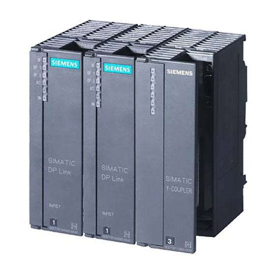
DP/PA Link and Y Link Bus Couplings
Brand:
Siemens
| Category:
Industrial Equipment
| Size: 1.28 MB
Table of Contents
Table of Contents
9
1 Product Overview
15
Bus Couplings
15
Integration in the Automation Landscape
16
What Is a Distributed I/O System
16
DP/PA Coupler
18
Integration of the DP/PA Coupler in the System Landscape
18
DP/PA Link
19
Integration of the DP/PA Link in the System Landscape
19
Y Link
20
Integration of the y Link in the System Landscape
20
2 Description of Components
21
DP/PA Coupler
22
Y Coupler
23
DP/PA Link
25
Y Link
28
Modifications with Respect to Precursor Modules
30
Compatibility to Precursor Modules
30
3 Installation
31
Installation Principles
31
Installing the DP/PA Coupler for Stand-Alone Operation
33
Installing the DP/PA Link for Non-Redundant Operation
34
Typical Configuration of the DP/PA Link for Non-Redundant Operation
34
Installing the DP/PA Link for Redundant Operation
36
Typical Configuration of the DP/PA Link for Redundancy Operation
36
Installing the y Link
39
Typical Configuration of the y Link
39
4 Wiring
43
Electrical Isolation and Grounding
43
General Rules and Regulations for Operation
44
Braided Screen of the PROFIBUS Cable on the Grounded Shield Bus
45
Operation with a Grounded Supply
46
Operation with Ungrounded Reference Potential
47
Configuration with a Grounded Supply
47
Configuration with Ungrounded Reference Potential
48
Connections
49
Wiring the DP/PA Coupler for Stand-Alone Operation
49
DP/PA Coupler Connections for Stand-Alone Operation
49
Wiring the DP/PA Link for Non-Redundant Operation
50
DP/PA Link Connections for Non-Redundant Operation
50
Wiring the DP/PA Link for Redundant Operation
51
DP/PA Link Connections for Redundancy Operation
51
Wiring the y Link
52
Y Link Connections
52
Connecting the Power Supply
53
Power Supply for IM
53
Connecting PROFIBUS-DP
54
Connecting PROFIBUS-PA
54
PROFIBUS-PA Connection
55
PA Bus Terminating Switch
56
Length of Insulation Stripped
56
5 Commissioning the DP/PA Coupler for Stand-Alone Operation
57
6 Commissioning the DP/PA Link
59
Configuration for S7 Standard Operation or Redundant Operation
61
Configuring the DP/PA Link
61
HW Config: DP/PA Link in Hardware Catalog
62
HW Config: Minimum Configuration of an S7-400H with a DP/PA Link
62
Configuring the PROFIBUS-PA Master System
63
Configuration for DP Standard Master Operation
64
Device Master Files
64
Configuring the DP/PA Link
65
Configuring PROFIBUS-PA Field Devices
66
Example of a Configuration with COM PROFIBUS
67
Setting the PROFIBUS Address of the IM
68
Entering the PROFIBUS Address
68
Example for Setting the PROFIBUS Address
69
7 Commissioning the y Link
71
Configuring the y Link
72
HW Config: y Link in Hardware Catalog
73
HW Config: Minimum Configuration of an S7-400H with a y Link
73
Configuring Underlying DP Slaves
74
8 Operation of the DP/PA Link and the y Link
75
Start-Up Delay
75
Start-Up Characteristics
76
Start-Up Behavior of the DP/PA Link in Non-Redundant Operation
76
Configured Start-Up Characteristics
76
Start-Up Behavior of the IM 157 after Power Is Switched on
77
Start-Up Behavior in Redundant Operation
78
Start-Up Behavior of the Two IM 157 Modules in Redundant Operation
79
Behavior Following Specific Events in Redundant Operation
80
Reading and Writing Records
81
Methods for Reading and Writing Records
81
Call Parameters for SFC 58 "WR_REC" and SFC 59 "RD_REC
82
Error Information of the IM 157
82
Identification Data
83
Identification Data
84
Replacing Faulty Modules
85
System Changes During Operation
85
System Changes in S7 Standard Operation
85
System Changes in Redundant Operation
86
IM 157 Firmware Update
86
Update Directly Via PROFIBUS-DP
88
Update Via MPI to the CPU and then Via PROFIBUS-DP
88
9 Diagnostics Using Leds
89
LED Displays of the IM 157
90
Status and Error Messages of the IM
90
LED Displays of the DP/PA Coupler
93
Status and Error Messages of the DP/PA Coupler
93
LED Displays of the y Coupler
94
Status Messages of the y Coupler
94
10 Diagnostics Using the User Program
95
Structure of the Slave Diagnosis
96
Length and Start Addresses of the Diagnostic Blocks in S7 Standard Operation and in Redundant Operation
96
Length and Start Addresses of the Diagnostic Blocks in DP
97
Structure of the Diagnostic Blocks
98
Structure of the Standard Diagnosis
98
Structure of Station Status
98
Structure of Station Status 1
99
Structure of Station Status
99
Module Diagnosis
100
Example of a Slot Assignment
100
Structure of the Device Identifier
100
Structure of the Module Diagnosis
101
Structure of the Module Status
102
Structure of the Status Message
104
Structure of the Status Message, Continued
104
Meaning of Byte X+36 in the Status Message
106
Structure of the H Status of the IM 157 in Redundant Operation on the S7-400H
107
Structure of the Interrupt Header on the DPV1V1-Capable DPV1 Master
109
Interrupt M Type (Byte X+1 in Interrupt Section)
109
Structure of the Additional Interrupt Information for the Insertion/Removal Interrupt
110
Call Parameters for SFC 59 "RD_REC
111
Call of the SFC 13 (DPNRM_DG) in the ob
113
Extension of PROFIBUS-PA with a DP/PA Link or DP/PA Couplers
120
Partyline and Star-Type Topology
121
Spur Line Length for the DP/PA Coupler
122
Use in Industrial Enrivonments
126
Pulse-Type Interference
129
Sinusoidal Interference
130
Transportation and Storage Conditions
131
Mechanical Ambient Conditions
132
Test for Mechanical Ambient Conditions
133
Climatic Ambient Conditions
133
Test Voltages
134
Examples of Directly Configurable DP Slaves
163
Examples of Usable DP Slaves
164
Cpus that Can be Used as I Slaves with Various I/O Ranges
165
Configuration Example (Excerpt from HW Config
166
Order Numbers for the Coupler Components
167
Order Numbers for the Configuration Accessories
167
Order Numbers for PROFIBUS-DP Accessories
168
Order Numbers for PROFIBUS-PA Accessories
168
Advertisement
Advertisement
Related Products
Siemens Simatic 6ES7 157-0AC80-0 A0 Series
Siemens 6ES7157-1AA00-0AB0
Siemens Simatic 6ES7 197-1LB00-0 A0 Series
Siemens 6ES7153-1AA03-0XB0
Siemens 6ES7153-2BA10-0XB0
Siemens 6ES7153-2BA70-0XB0
Siemens 6ES7153-4AA00-0XB0
Siemens 6ES7153-4AA01-0XB0
Siemens 6ES7153-2BA82-0XB0
Siemens 6ES7197-1LB00-0XA0
Siemens Categories
Industrial Equipment
Controller
Control Unit
Oven
Washer
More Siemens Manuals
Login
Sign In
OR
Sign in with Facebook
Sign in with Google
Upload manual
Upload from disk
Upload from URL