Siemens SIMATIC NET SCALANCE W M766 Series Operating Instructions Manual
Hide thumbs
Also See for SIMATIC NET SCALANCE W M766 Series:
- Operating instructions manual (76 pages) ,
- Operating instructions manual (86 pages)
Table of Contents
Advertisement
SCALANCE WxM766
SIMATIC NET
Industrial Wireless LAN
SCALANCE WxM766
Operating Instructions
03/2022
C79000-G8976-C617-03
Introduction
Safety notices
Security
recommendations
Description of the device
Assembly and
disassembly
Connection
Maintenance and cleaning
Troubleshooting
Technical specifications
Dimension drawing
Approvals
1
2
3
4
5
6
7
8
9
10
11
Advertisement
Table of Contents

Related Manuals for Siemens SIMATIC NET SCALANCE W M766 Series


Summary of Contents for Siemens SIMATIC NET SCALANCE W M766 Series
- Page 1 SCALANCE WxM766 Introduction Safety notices Security SIMATIC NET recommendations Description of the device Industrial Wireless LAN SCALANCE WxM766 Assembly and disassembly Connection Operating Instructions Maintenance and cleaning Troubleshooting Technical specifications Dimension drawing Approvals 03/2022 C79000-G8976-C617-03...
- Page 2 Note the following: WARNING Siemens products may only be used for the applications described in the catalog and in the relevant technical documentation. If products and components from other manufacturers are used, these must be recommended or approved by Siemens. Proper transport, storage, installation, assembly, commissioning, operation and maintenance are required to ensure that the products operate safely and without any problems.
-
Page 3: Table Of Contents
Table of contents Introduction ............................. 5 Safety notices ............................9 Security recommendations ........................11 Description of the device ........................19 Structure of the type designation ....................19 Structure of the article number ....................19 Device view ............................ 20 Components of the product ......................21 Accessories ............................ - Page 4 Table of contents Connection ............................. 49 Safety when connecting up ......................49 Power supply ..........................55 Ethernet ............................57 Antennas ............................58 Digital input/output ........................59 Grounding ............................61 Replacing a CLP ..........................62 Maintenance and cleaning ........................65 Troubleshooting ............................ 67 Downloading new firmware using TFTP without WBM and CLI ...........
-
Page 5: Introduction
Documentation on the Internet You can find the current version of the document on the Internet at (https://support.industry.siemens.com/cs/de/en/ps/28575/man) Enter the name or article number of the product in the search filter. SCALANCE WxM766 Operating Instructions, 03/2022, C79000-G8976-C617-03... - Page 6 Firmware The firmware is signed and encrypted. This ensures that only firmware created by Siemens can be downloaded to the device. The firmware is available on the Internet pages of the Siemens Industry Online Support: (https://support.industry.siemens.com/cs/de/en/ps/28575/dl) SCALANCE WxM766 Operating Instructions, 03/2022, C79000-G8976-C617-03...
- Page 7 (https://support.industry.siemens.com/cs/ww/en/view/109479891)). Note the different national regulations. Device defective If a fault develops, send the device to your SIEMENS representative for repair. Repairs on-site are not possible. Trademarks The following and possibly other names not identified by the registered trademark sign ®...
- Page 8 Introduction SCALANCE WxM766 Operating Instructions, 03/2022, C79000-G8976-C617-03...
-
Page 9: Safety Notices
Safety notices CAUTION To prevent injury and damage, read the manual before using the device. Read the safety notices Note the following safety notices. These relate to the entire working life of the device. You should also read the safety notices relating to handling in the individual sections, particularly in the sections "Installation"... - Page 10 Safety notices SCALANCE WxM766 Operating Instructions, 03/2022, C79000-G8976-C617-03...
-
Page 11: Security Recommendations
OpenVPN). • Separate connections correctly (WBM, SSH etc.). • Check the user documentation of other Siemens products that are used together with the device for additional security recommendations. • Using remote logging, ensure that the system protocols are forwarded to a central logging server. - Page 12 Security recommendations • Replace the default passwords for all user accounts, access modes and applications (if applicable) before you use the device. • Define rules for the assignment of passwords. • Use passwords with a high password strength. Avoid weak passwords, (e.g. password1, 123456789, abcdefgh) or recurring characters (e.g.
- Page 13 • Verify certificates based on the fingerprint on the server and client side to prevent "man in the middle" attacks. Use a second, secure transmission path for this. • Before sending the device to Siemens for repair, replace the current certificates and keys with temporary disposable certificates and keys, which can be destroyed when the device is returned.
- Page 14 Initialization Vector Implementation Information Disclosure Vulnerability (for example, BEAST). • Ensure that the latest firmware version is installed, including all security-related patches. You can find the latest information on security patches for Siemens products at the Industrial Security (https://www.siemens.com/industrialsecurity) or ProductCERT Security Advisories (https://www.siemens.com/cert/en/cert-security-advisories.htm) website.
- Page 15 Security recommendations Secure/ non-secure protocols • Use secure protocols if access to the device is not prevented by physical protection measures. • Disable or restrict the use of non-secure protocols. While some protocols are secure (e.g. HTTPS, SSH, 802.1X, etc.), others were not designed for the purpose of securing applications (e.g.
- Page 16 Security recommendations List of available services The following is a list of all available services and their ports through which the device can be accessed. The table includes the following columns: • Service The services that the device supports. • Protocol/port number Port number assigned to the protocol.
- Page 17 Security recommendations Service Protocol / Default port Configurable Authenticati- Encryption Port number status Port Service DHCP Client IPv4 UDP/68 Outgoing only ✓ DHCP Client IPv6 UDP/546 Outgoing only ✓ DNS Client TCP/53 Outgoing only ✓ UDP/53 HTTP TCP/80 Open ✓ ✓...
- Page 18 Security recommendations The following is a list of all available Layer 2 services through which the device can be accessed. The table includes the following columns: • Layer 2 service The Layer 2 services that the device supports. • Default status The default status of the service (open or closed).
-
Page 19: Description Of The Device
Description of the device Structure of the type designation The type designation of the device is made up of several parts that have the following meaning: Structure of the article number The article number of the device is made up of several parts that also reflect the properties of the device: SCALANCE WxM766 Operating Instructions, 03/2022, C79000-G8976-C617-03... -
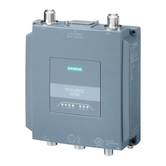
Page 20: Device View
Description of the device 4.3 Device view Device view ① LED display ② R1A1 antenna connector, female N-Connect type ③ Screw-down cover: - for the reset button and - for the PLUG slot (CLP) ④ R2A1 antenna connector, female N-Connect type ⑤... -
Page 21: Components Of The Product
– 1 x digital input/digital output • One grounding screw Please check that the consignment you have received is complete. If the consignment is incomplete, contact your supplier or your local Siemens office. Note Not included with the product The following components do not ship with the product: •... -
Page 22: Installation
Description of the device 4.5 Accessories 4.5.1 Installation Component Description Article number Mounting adapter Adapter for mounting on a 35mm DIN 6GK5798-8MF00-0AA1 rail according to DIN EN 50 022 DIN rail Angle adapter 90° angle adapter for rail mounting, 6GK5798-8MF00-0AB1 only in conjunction with SCALANCE MUM856-1, WAM/ WUM766-1;... -
Page 23: Industrial Ethernet
Description of the device 4.5 Accessories 4.5.3 Industrial Ethernet You will find information on the cabling for communication networks in the industry on the Internet pages of Siemens Industry Online Support (https://support.industry.siemens.com/cs/ww/en/view/109766358). 4.5.3.1 Data cables Cables Industrial Ethernet (pre-assembled) Component... -
Page 24: Data Plug-In Connector
Description of the device 4.5 Accessories Cables Industrial Ethernet (sold by the meter) Component Description Article number IE FC TP Standard Cable 8-wire shielded TP installation cable for 6XV1878-2A GP 4x2 universal application (AWG 24) Sold by the meter IE FC TP Flexible Cable GP 8-wire shielded TP installation cable for 6XV1878-2B occasional movement... -
Page 25: Plug-In Connector
Description of the device 4.5 Accessories Component Description Article number Length 1m 6XV1801-2CH10 Length 1.5m 6XV1801-2CH15 Length 2m 6XV1801-2CH20 Length 3m 6XV1801-2CH30 Length 5m 6XV1801-2CH50 Length 10m 6XV1801-2CN10 Length 15m 6XV1801-2CN15 Cables DI/DO interface (sold by the meter) Component Description Article number SIMATIC NET CONTROL 5-wire power cable, stranded wire, 5 x... -
Page 26: Power Supply
Description of the device 4.5 Accessories 4.5.5 Power supply 4.5.5.1 Energy cable Power cables (pre-assembled) Component Description Article number M12 connecting cable, L- Flexible plug-in energy cable to connect 6XV1801-6D* coded, 4-pin M12-180 the power supply 24 V DC, 4-wire, preassembled with a 4-pin M12 plug and an M12 socket (L-coded) M12 connecting cable, L-... -
Page 27: Flexible Connecting Cables, Antennas And Accessories
4.5 Accessories 4.5.6 Flexible connecting cables, antennas and accessories You will find an overview of the IWLAN products and their accessories in the Order overview (https://support.industry.siemens.com/cs/ww/en/view/109766333). 4.5.6.1 Flexible connecting cables Flexible connecting cable N-Connect/R-SMA Flexible connecting cable for connecting an antenna to a SCALANCE W device with R-... -
Page 28: Lightning Protection
Description of the device 4.5 Accessories Flexible connecting cable IWLAN QMA/N-Connect male/female Adapter cable for connecting a MIMO antenna with QMA connectors to the flexible connecting cables; preassembled with one QMA male and one N-Connect female connector; scope of delivery 3 units: Length Article number 6XV1875-5JH10... -
Page 29: Antennas
Internet pages of Siemens Industry Online Support (https://support.industry.siemens.com/cs/de/en/view/109802595). • The country-specific and channel-dependent maximum permissible antenna gain You will find further information on this in the reference document "Approvals SCALANCE W700 802.11ax" on the Internet pages of the Siemens Industry Online Support (https://www.siemens.com/wireless-approvals). Type Properties... -
Page 30: Led Display
Description of the device 4.6 LED display Type Properties Article number ANT795-4MX Omnidirectional antenna, 2/2.5 dBi, 6GK5795-4MX00-0AA0 2.4 GHz and 5 GHz, IP69K, N-Connector male ANT795-6MP Omnidirectional antenna, 5/7 dBi, 2.4 GHz 6GK5795-6MP00-0AA0 and 5 GHz, IP65/67, N-Connector female IWLAN RCoax Cable Omni antenna, 0 dBi 2.400 - 2.485 GHz, N- 6XV1875-2A 2,4 GHz PE 1/2"... - Page 31 Description of the device 4.6 LED display Color Meaning Power supply L1 too low. Green Power supply L1 is applied. Power supply L2 too low. Green Power supply L2 is applied. The device is not supplied using PoE. Green The device is supplied using PoE. Note: If the device is simultaneously connected to 24V voltage (L1/L2), the power supply to the device is via L1/L2.
- Page 32 Description of the device 4.6 LED display Color Meaning No fault/error. Yellow: Sleep mode is active. The device is booting, an error has occurred or the bootloader is waiting for a new firmware file, which you can load via TFTP, see "Loading new firmware via TFTP without WBM and CLI (Page 67)".
-
Page 33: Reset Button
Description of the device 4.7 Reset button Reset button Position NOTICE Loss of water and dust protection If the cover is not mounted correctly, the device is not water and dust proof. The reset button ① is located behind the screw-down cover on the top of the housing. ①... -
Page 34: Configuration License Plug
Description of the device 4.8 Configuration License PLUG NOTICE Inadvertent reset An inadvertent reset can cause disturbances and failures in a configured network with further consequences. Configuration License PLUG The CLP (Configuration License PLUG) is used to transfer the configuration of the old device to the new device when a device is replaced. - Page 35 – The configuration data of the device is stored in a secured memory area of the CLP. This secured memory area can only be accessed via the authentication of the Siemens device. – The device checks whether a CLP is inserted at one second intervals. If the device detects that the CLP has been removed, it restarts automatically.
- Page 36 Description of the device 4.8 Configuration License PLUG SCALANCE WxM766 Operating Instructions, 03/2022, C79000-G8976-C617-03...
-
Page 37: Assembly And Disassembly
Assembly and disassembly Safety notices for installation Safety notices When installing the device, keep to the safety notices listed below. NOTICE Improper mounting Improper mounting may damage the device or impair its operation. • Before mounting the device, always ensure that there is no visible damage to the device. - Page 38 Assembly and disassembly 5.1 Safety notices for installation WARNING If the device is installed in a cabinet, the inner temperature of the cabinet corresponds to the ambient temperature of the device. WARNING The device is intended for indoor use only. Safety notices on use in hazardous areas General safety notices relating to protection against explosion WARNING...
- Page 39 Assembly and disassembly 5.1 Safety notices for installation Safety notices when using according to FM If you use the device under FM conditions you must also keep to the following safety notices in addition to the general safety notices for protection against explosion: WARNING EXPLOSION HAZARD The equipment is intended to be installed within an enclosure/control cabinet.
-
Page 40: Types Of Installation
Assembly and disassembly 5.2 Types of installation WARNING Open equipment The devices are "open equipment" according to the standard IEC 61010-2-201 or UL 61010-2-201 / CSA C22.2 No. 61010-2-201. To fulfill requirements for safe operation with regard to mechanical stability, flame retardation, stability, and protection against contact, the following alternative types of installation are specified: •... -
Page 41: Wall Mounting
Assembly and disassembly 5.3 Wall mounting Note Installation in the upward position when using the device according to UL Operation in the upward position (e.g. desktop operation) has not been tested according to UL for this device and is therefore not permitted. Wall mounting Note Depending on the mounting surface, use suitable fittings. -
Page 42: Din Rail Mounting
Assembly and disassembly 5.5 DIN rail mounting DIN rail mounting 5.5.1 Installation with the DIN rail mounting adapter The DIN rail mounting adapter is not included with the product, see Accessories (Page 22). Mounting 1. Screw (M3 x 8, tightening torque 0.8 Nm) the DIN rail mounting adapter onto the rear of the device. - Page 43 Assembly and disassembly 5.5 DIN rail mounting 3. Press the device against the DIN rail until the DIN rail slider catch locks into place. 4. Connect the power supply, refer to the section "Power supply (Page 55)". 5. Fit the antennas, refer to the section "Antennas (Page 58)". Uninstalling 1.
- Page 44 Assembly and disassembly 5.5 DIN rail mounting 4. Tilt the device forward and remove the device from the DIN rail. 5. Loosen the screws of the DIN rail mounting adapter completely. SCALANCE WxM766 Operating Instructions, 03/2022, C79000-G8976-C617-03...
-
Page 45: Mounting With Bracket Support
Assembly and disassembly 5.5 DIN rail mounting 5.5.2 Mounting with bracket support With the bracket support the device can be mounted on a DIN rail rotated through 90° The DIN rail mounting adapter and bracket holder are not included with the product, see Accessories (Page 22). - Page 46 Assembly and disassembly 5.5 DIN rail mounting Mounting 1. Screw (M4 x 20, tightening torque 1.8 Nm) the angle bracket onto the rear of the device. 2. Place the device on the upper edge of the DIN rail 3. Press the device against the DIN rail until the DIN rail slider catch locks into place.
- Page 47 Assembly and disassembly 5.5 DIN rail mounting 4. Connect the power supply, refer to the section "Power supply". 5. Fit the antennas, refer to the section "Antennas". Uninstalling 1. Turn off the power to the device. 2. Disconnect all connected cables. 3.
- Page 48 Assembly and disassembly 5.5 DIN rail mounting SCALANCE WxM766 Operating Instructions, 03/2022, C79000-G8976-C617-03...
-
Page 49: Connection
Connection Safety when connecting up Safety notices When connecting up the device, keep to the safety notices listed below. Note Close unused sockets Close all unused M12 sockets with protective caps (tightening torque at least 0.4 Nm) to achieve the specified type of protection. Lightning protection WARNING Danger due to lightning strikes... - Page 50 Connection 6.1 Safety when connecting up Note The requirements of EN61000-4-5, surge immunity tests on power supply lines, are met only when a Blitzductor is used with 24 VDC: BVT AVD 24 article number: 918 422 Manufacturer: DEHN+SÖHNE GmbH+Co.KG, Hans Dehn Str. 1, Postfach 1640, D - 92306 Neumarkt, Germany Supply voltage WARNING...
- Page 51 Connection 6.1 Safety when connecting up NOTICE Damage to the device due to potential differences To fully eliminate the influence of electromagnetic interference, the device must be grounded. There must be no potential difference between the following parts, otherwise the device or other connected device could be severely damaged: •...
- Page 52 Connection 6.1 Safety when connecting up WARNING Lack of equipotential bonding If there is no equipotential bonding in hazardous areas, there is a risk of explosion due to equalizing current or ignition sparks. • Ensure that equipotential bonding is available for the device. WARNING Unprotected cable ends There is a risk of explosion due to unprotected cable ends in hazardous areas.
- Page 53 Connection 6.1 Safety when connecting up WARNING Transient overvoltages Take measures to prevent transient overvoltages of more than 40% of the rated voltage (or more than 119 V). This is guaranteed if you only operate the devices with SELV (safety extra-low voltage) or PELV (protective extra low voltage). WARNING Suitable cables at high ambient temperatures in hazardous area At an ambient temperature of ≥...
- Page 54 Connection 6.1 Safety when connecting up WARNING Restricted area of application This equipment is suitable for use in Class I, Zone 2, Group IIC or non-hazardous locations only. Safety information when using in accordance with UL 61010-2-201 If you use the device under UL 61010-2-201 conditions you must also keep to the following safety notices in addition to the general safety notices for protection against explosion: NOTICE...
-
Page 55: Power Supply
Connection 6.2 Power supply NOTICE The digital outputs are not permitted to come into contact with hazardous voltages and non-energy limited circuits. The permissible nonhazardous voltages are SELV/PELV as per UL 61010-2-201. The energy limited circuit as per clause 9.4 of UL 61010-1 or LPS of UL 60950 or Class 2 of UL 1310 or UL 5085-1 &... - Page 56 Connection 6.2 Power supply • Permitted tensile load at least 100 N. • Listing of the cables according to the national installation regulations. In areas where NEC or CEC applies: Type PTLC or ITC To connect the functional ground, use a copper cable of category AWG18 or a cable with a cross-section ≥...
-
Page 57: Ethernet
Connection 6.3 Ethernet Power over Ethernet (PoE) Note Before you pull a plug via which the device is supplied with power using PoE, disable the relevant PoE power supply. Note No power sourcing equipment (PSE) The SCALANCE WxM766-1 devices cannot be used as PoE power supply for other devices. -
Page 58: Antennas
Connection 6.4 Antennas Connecting Ethernet ports 1. Connect the plug and socket. Make sure that they lock in place correctly. 2. Tighten the knurled screw (torque 1 Nm). Antennas The SCALANCE WxM766-1 has two antenna connectors of the N-Connector female type. Figure 6-1 Antenna connectors ①... -
Page 59: Digital Input/Output
Connection 6.5 Digital input/output Note Terminating resistor Any connections that are not in use must be fitted with a terminating resistor, see Accessories (Page 21). An antenna must always be connected to the antenna connector as soon as the WLAN interface is switched on. - Page 60 Connection 6.5 Digital input/output Rules for wiring • To wire the digital input/output, use a copper cable of category AWG18-16 or a cable with a cross-section of 0.75 to 1.5 mm • Always wire the digital input/output in pairs. • The maximum permissible cable length is 3 m. Position / Assignment Example: Ground...
-
Page 61: Grounding
Connection 6.6 Grounding Grounding EMC disturbances are diverted to ground via the functional ground. This ensures the immunity of the data transmission. The grounding screw is identified by the following symbol for the functional ground Protective earth/functional ground The connection of the reference potential surface with the protective earth system is normally in the cabinet close to the power feed-in. -
Page 62: Replacing A Clp
Connection 6.7 Replacing a CLP Replacing a CLP Position The CLP slot is at the top of the device enclosure under a cover, see Reset button (Page 33). ① M3 screws (Torx T10) ② Slot cover ③ Removing a CLP Note Loss of the configuration The reset button is located directly beside the slot for the CLP. - Page 63 Connection 6.7 Replacing a CLP 3. To release the CLP ③, insert a screwdriver between the front edge of the CLP (A) and the slot. 4. Remove the CLP from the slot. 5. Close the slot cover (torque 0.8 Nm) to ensure that the device maintains the degree of protection IP65.
- Page 64 Connection 6.7 Replacing a CLP SCALANCE WxM766 Operating Instructions, 03/2022, C79000-G8976-C617-03...
-
Page 65: Maintenance And Cleaning
Maintenance and cleaning WARNING Unauthorized repair of devices in explosion-proof design Risk of explosion in hazardous areas • Repair work may only be performed by personnel authorized by Siemens. WARNING Impermissible accessories and spare parts Risk of explosion in hazardous areas •... - Page 66 Maintenance and cleaning SCALANCE WxM766 Operating Instructions, 03/2022, C79000-G8976-C617-03...
-
Page 67: Troubleshooting
Firmware The firmware is signed and encrypted. This ensures that only firmware created by Siemens can be downloaded to the device. You can download new firmware to the device using TFTP. To do this, the device does not need to be reachable either using Web Based Management (WBM) or using the Command Line Interface (CLI). -
Page 68: Restoring The Factory Settings
Troubleshooting 8.2 Restoring the factory settings Restoring the factory settings NOTICE Previous settings If you reset, all the settings you have made will be overwritten by factory defaults. NOTICE Inadvertent reset An inadvertent reset can cause disturbances and failures in a configured network with further consequences. - Page 69 Troubleshooting 8.2 Restoring the factory settings Via the configuration You will find detailed information on resetting the device parameters using the WBM and CLI in the configuration manuals: • Web Based Management, section "Restart" • Command Line Interface, section "Reset and Defaults" SCALANCE WxM766 Operating Instructions, 03/2022, C79000-G8976-C617-03...
- Page 70 Troubleshooting 8.2 Restoring the factory settings SCALANCE WxM766 Operating Instructions, 03/2022, C79000-G8976-C617-03...
-
Page 71: Technical Specifications
• SCALANCE WAM766-1 EEC • SCALANCE WUM766-1 Note You will find detailed information on the transmit power and receiver sensitivity in the document "Performance data SCALANCE W700 802.11ax" on the Internet at (https://support.industry.siemens.com/cs/de/en/view/109797829). Technical specifications Data transfer Ethernet transfer rate 10/100/1000 Mbps Wireless transmission rate 1 ... - Page 72 Technical specifications Technical specifications Wireless interface Antenna connector Quantity Design N-Connect socket Impedance 50 Ω nominal Permitted antenna wire lengths < 30 m Frequency range 2412 ... 2480 MHz 4920 ... 5875 MHz Electrical data Direct 24 VDC supply Supply voltage from socket 24 VDC Safe Extra Low Voltage (SELV) Type of current Permitted...
- Page 73 Technical specifications Technical specifications Digital output Quantity Design M12 socket, A-coded Rated voltage 24 V DC safety extra-low voltage (SELV) Max. input voltage 30 V DC safety extra-low voltage (SELV) Fuse 0.5 A Max. cable length < 3 m Cables should be routed in pairs Properties Output isolated from electronics Permissible ambient conditions...
- Page 74 Technical specifications SCALANCE WxM766 Operating Instructions, 03/2022, C79000-G8976-C617-03...
-
Page 75: Dimension Drawing
Note CAx data You can find the CAx data on the Internet at (https://www.automation.siemens.com/bilddb/index.aspx?lang=en) 1. Click on the "CAx data" link in the "Direct Links" area. The Industry Image Database page is loaded. 2. Enter the name or article number of the product in the search filter. - Page 76 Dimension drawing Side view SCALANCE WxM766 Operating Instructions, 03/2022, C79000-G8976-C617-03...
- Page 77 Dimension drawing Rear view Rear view with bore holes for VESA bracket 75 x 75, 4x M4, thread depth 8.5 mm SCALANCE WxM766 Operating Instructions, 03/2022, C79000-G8976-C617-03...
- Page 78 Dimension drawing SCALANCE WxM766 Operating Instructions, 03/2022, C79000-G8976-C617-03...
-
Page 79: Approvals
You will find the approvals of the products in the reference work "Approvals SCALANCE W700 802.11ax" on the Internet pages of the Siemens Industry Online Support (https://support.industry.siemens.com/cs/ww/en/view/109802595). You will find the current approvals for the product on the Internet pages of the Siemens Industry Online Support (https://support.industry.siemens.com/cs/ww/en/ps/28575/cert). - Page 80 Approvals SCALANCE WxM766 Operating Instructions, 03/2022, C79000-G8976-C617-03...
-
Page 81: Index
Index Functional grounding, 61 Accessories, 21 Antenna cables, 27 Grounding, 50, 61 Antennas, 27, 58 Article number, 5 Structure, 19 Interfaces, 71 Button Reset, 33 LED display, 30 Lightning protection, 49 Cables Permitted lengths, 71 Mounting CAx data, 75 DIN rail, 42 Certification ID, 5 DIN rail, rotated by 90 degrees, 45 CLP, 34... - Page 82 Index Technical specifications, 71 Type designation, 19 Wall mounting, 41 SCALANCE WxM766 Operating Instructions, 03/2022, C79000-G8976-C617-03...
Need help?
Do you have a question about the SIMATIC NET SCALANCE W M766 Series and is the answer not in the manual?
Questions and answers