Hitachi HIDIC EH-150 Applications Manual
Profibus-dp master module
Hide thumbs
Also See for HIDIC EH-150:
- Applications manual (117 pages) ,
- Instruction manual (29 pages) ,
- Applications manual (20 pages)
Table of Contents
Advertisement
Quick Links
Advertisement
Table of Contents

Related Manuals for Hitachi HIDIC EH-150


Summary of Contents for Hitachi HIDIC EH-150
- Page 1 HITACHI PROGRAMMABLE CONTROLLER PROFIBUS-DP MASTER MODULE APPLICATION MANUAL...
- Page 2 Personnel who are to install and operate the equipment should carefully study this manual and any others referred to by it prior to installation and / or operation of the equipment. Hitachi, Ltd. constantly strives to improve its products, and the equipment and the manual(s) that describe it may be different from those already in your possession.
- Page 3 Hitachi is free from defects in material and workmanship under normal use and service. The obligation of Hitachi under this warranty shall be limited to the repair or exchange of any part or parts which may prove defective under normal use and service within eighteen (18) months from the date of manufacture or twelve (12) months from the date of installation by the original purchaser which ever occurs first, such defect to be disclosed to the satisfaction of Hitachi after examination by Hitachi of the allegedly defective part or parts.
- Page 4 As the product works with user program and Hitachi, Ltd. cannot test all combination of user program components, it is assumed that a bug or bugs may happen unintentionally. If it is happened: please inform the fact to Hitachi, Ltd. or its representative.
- Page 5 Safety Precautions Read this manual and related documents thoroughly before installing, operating, performing preventive maintenance or performing inspection, and be sure to use the unit correctly. Use this product after acquiring adequate knowledge of the unit, all safety information, and all cautionary information. Also, make sure this manual enters the possession of the chief person in charge of safety maintenance.
- Page 6 2. About wiring REQUIRED Always perform grounding (FE terminal). If grounding is not performed, there is a risk of electric shocks and malfunctions. CAUTION Connect power supply that meets rating. If a power supply that does not meet rating is connected, fire may be caused. The wiring operation should be performed by a qualified personnel.
- Page 7 4. About preventive maintenance DANGER Do not connect the of the battery in reverse. Also, do not charge, disassemble, heat, place in fire, or short circuit the battery. There is a risk of explosion or fire. PROHIBITED Do not disassemble or modify the unit. These actions may result in fire or malfunction.
-
Page 8: Table Of Contents
Table of contents Chapter 1 INTRODUCTION Before Use ..............................1- 1 Technical features............................1- 1 Chapter 2 STRUCTURE and SPECIFICATION 2-1 to 2-2 Structure and Parts name ........................... 2- 1 Specification .............................. 2- 2 Chapter 3 CONFIGURATIONS 3-1 to 3-7 System configurations .......................... -
Page 9: Introduction
Chapter 1 INTRODUCTION We appreciate that you have selected the EH-150 Profibus Master Module of the Hitachi programmable logic controller. This application manual describes how to properly operate the EH-150 Profibus Module. Carefully read the manual to familiarize yourself with the procedures respectively of installation , operation, and maintenance and check. -
Page 10: Structure And Specification 2-1 To
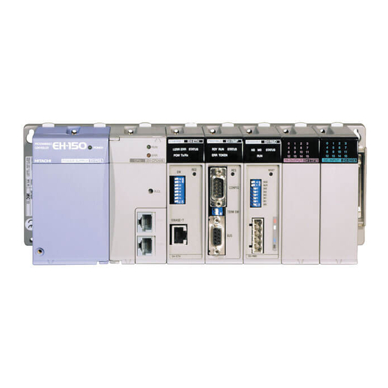
Chapter 2 STRUCTURE and SPECIFICATION Chapter 2 STRUCTURE and SPECIFICATION 2.1 Structure and Parts name EH-RMP Name and function Model 1) Lock button 2) LEDs Approx. 130g Weight 3) Connector 1 Approx. 600mA Current 4) Reset switch dimension (mm) 5) DIP switch 6) Termination switch 7) Connector 2 Name... -
Page 11: Specification
Chapter 2 STRUCTURE and SPECIFICATION 2.2 Specification ITEM Specification Power source Supplied from power Supply Module General Operating ambient temperature 0 to 55 degree Storage ambient temperature -10 to 75 degree Operating ambient humidity No condensation 20 to 90 % RH Storage ambient humidity No condensation 10 to 90 % RH Vibration resistance... -
Page 12: Chapter 3 Configurations 3-1 To
Chapter 3 CONFIGURATIONS Chapter 3 CONFIGURATIONS 3.1 System configurations Two modules per CPU 0 to 2 slot of basic unit only(can’t mount other slot) 10 11 12 13 14 15 Basic unit Extension unit Up to 124 DP-Slaves. EH-IOCP is up to 99 modules. 10 11 12 Basic unit Extension unit... -
Page 13: Start Up
Chapter 3 CONFIGURATIONS 3.2 Start up To operation this module normally, the making a setup which is shown in the following figure is necessary. (1) Set the DIP switch. Refer to chapter 3.2.1 . (2) Set the termination switch. . Refer to chapter 3.2.2 . (3) Set the configuration data from the configuration tool. - Page 14 Chapter 3 CONFIGURATIONS (3) Copy mode When the CPU is switched from RUN to STOP position, the EH-RMP continues to copy the data present in the link output data. This mode is effective when using the EH-150 CPU(EH-CPU308/316) ROM version 02 (software version 2.12) and later.
- Page 15 Chapter 3 CONFIGURATIONS Configuration from configurator 3.2.3 The configuration of the EH-RMP is accomplished by the configurator colled SyConDP. For general information about the configurator, please refer to the manual for this configurator. (1) The entry of the EH-RMP Click the Master icon , and click left-top corner on “Device” area. Select the “Profibus-DP Master”, and set the station address.
- Page 16 Chapter 3 CONFIGURATIONS (3) Make configuration and parameter data Double click on the selected device. And make the configuration data and parameter data. In the configuration data is set the byte offset address from start address of output link area or input link area. For the details of the configuration data and the parameter data to the slave equipment, please refer to the manual of each slave equipment.
- Page 17 Chapter 3 CONFIGURATIONS (4) Set the bus parameter In the menu Set-up/Bus parameter the window shows the actual bus parameters. Changing the baud rate has the consequence, that all other parameters will be re-calculated, The Highest Station Address is the highest bus address up to which the master will search for other master. This should not be set below the master address.
- Page 18 Chapter 3 CONFIGURATIONS Configuration from Ladder Editor 3.2.3 The EH-150 CPU has two link areas of 1024 words (No.1 LINK and No.2 LINK). The EH-RMP operates in the EH-150 system as a LINK module. The first EH-RMP in a rack uses No.1 LINK area and the second EH-RMP uses No.2 LINK area .
-
Page 19: Chapter 4 Installation And Wiring 4-1 To
Chapter 4 Installation and Wiring Chapter 4 Installation and Wiring 4.1 Installation of Module EH-RMP can be installed in 0-2 slot on the basic base unit. Install and uninstall the module after turn off the base unit power source. 4.2 Loading the Module (1)Installing Hook the claw at the lower section of the module to the hole in the base. -
Page 20: Wiring
Chapter 4 Installation and Wiring 4.3 Wiring For information about installation of the Profibus DP fieldbus, please refer to the document : Installation Guideline for PROFIBUS-DP/FMS from PNO, Order No. 2.112. Profibus homepage on the Internet: http://www.profibus.com 4.3.1 Profibus port EH-RMP has D-sub 9 pin female connector for Profibus port. - Page 21 Chapter 4 Installation and Wiring 4.3.2 Cable parameters The bus cable is specified in EN 50170 part 8-2 as ”Cable Type A”, and should comply with the parameters in the table below. Cable Type B, which is also described in EN 50170, is outdated and should no longer be used. Example of cable for Profibus DP: Siemens, Order number: 6XV1830-0EH10 Table 4.2 Cable parameters Parameter...
- Page 22 Chapter 4 Installation and Wiring 4.3.4 Configuration port EH-RMP has D-sub 9 pin male connector for configuration port. The configuration port on EH-RMP is connected to a PC COM port via an ordinary null modem cable. Table 4.4 Pin order of configuration port Pin number Signal Description...
-
Page 23: Normal Operation
Chapter 5 Normal Operation Chapter 5 Normal Operation 5.1 Start-up Sequence When the power is turned on the EH-RMP will perform an internal hardware check. The STATUS LED will flash Green -> Red -> Green -> Red and then start flashing green with 1Hz until the initialization sequence is finished, then the STATUS LED should be constantly lit green. -
Page 24: Chapter 6 Indications 6-1 To
Chapter 6 Indications Chapter 6 Indications The EH-RMP can give indications to the user in two different ways. The first way is via the five indications LED at the top of the module and the second way is via the special internal output of EH-150 CPU, where detailed information about the Profibus DP network is available for the PLC programmer. - Page 25 Chapter 6 Indications 6.1.1.4 Recoverable errors The status LED will flash green if the error is recoverable. The flashing sequence are built up according to the figures below. Color: Green Two flashed: 1000 1250 1500 1750 2000 2250 2500 2750 3000 (ms) Color: Green Three flashed:...
- Page 26 Chapter 6 Indications 6.1.1.5 Non-Recoverable errors The status LED will flash red if the error is non-recoverable. The flashing sequence are built up according to the same pattern as for the recoverable errors. Table 6.2 Non-recoverable errors Number of Fault Cause Action flashes...
-
Page 27: Link Information Flag Area
Chapter 6 Indications Link Information Flag Area In the Link information flag area, the LADDER EDITOR can get valuable information about the Profibus DP fieldbus. The data is represented in Motorola format in the EH-150 CPU. OFFSET address(word) Start address of LINK No.1 : WRF0E0 Start address of LINK No.2 : WRF140 Table 6.7 Contents in the LINK information flag area Reserved... - Page 28 Chapter 6 Indications 6.2.1 Error Code Table 6.8 Error code Link module Link address Notes Link No. 1 WRF0E0 Low byte (High byte not used) Link No. 2 WRF140 Low byte (High byte not used) The following error codes can be present in this register: hex00 No error hex01 Failed to initialize Profibus DP master.
- Page 29 Chapter 6 Indications 6.2.4 Error number Table 6.12 Error number Link module Link address Notes Link No. 1 WRF0E5 High byte Link No. 2 WRF145 High byte This register can contain two types of errors, Internal errors and External errors, depending on the value of the register ‘Error remote address’.
- Page 30 Chapter 6 Indications 6.2.5 Error remote address Table 6.15 Error remote address Link module Link address Notes Link No. 1 WRF0E5 Low byte Link No. 2 WRF145 Low byte If this register is equal to 0xFF, an internal master error, otherwise this register indicates the node number of a faulty node. The error code is specified in the ‘Error number’...
- Page 31 Chapter 6 Indications 6.2.10 Device error Table 6.20 Device error Link module Link address Notes Link No. 1 WRF107 High byte (Low byte not used) Link No. 2 WRF167 High byte (Low byte not used) Indicates internal faults in the Profibus DP master according to the table below. Table 6.21 Detail of device error Value Name...
-
Page 32: Chapter 7 Daily And Periodic Inspection
Chapter 7 Daily and Periodic Inspection Chapter 7 Daily and Periodic Inspection In order to use the EH-RMP functions in the most desirable condition and maintain the system to operate normally, it is essential to conduct daily and periodic inspections. (1) Daily inspection Verify the following items while the system is running. - Page 33 Chapter 8 Troubleshooting Chapter 8 Troubleshooting Trouble Possible cause Action The ERR LED is lit even if the All nodes that are configured in the Connect all nodes to make the ERROR LED master are not present on the network. turn off.
Need help?
Do you have a question about the HIDIC EH-150 and is the answer not in the manual?
Questions and answers