
Related Manuals for Infineon DriveCard XMC4400 V1


Summary of Contents for Infineon DriveCard XMC4400 V1
- Page 1 M ot or Contro l Applic atio n Kit For XMC4000 Family K IT_XM C 44 00_ DC_V1 XMC4400 Drive Card V1.0 B oa rd User„s M anual Revision 1.0, 2013-11-05 Mic roco ntroll er...
- Page 2 Infineon Technologies components may be used in life-support devices or systems only with the express written approval of Infineon Technologies, if a failure of such components can reasonably be expected to cause the failure of that life-support device or system or to affect the safety or effectiveness of that device or system. Life support devices or systems are intended to be implanted in the human body or to support and/or maintain and sustain and/or protect human life.
- Page 3 KIT_XMC4400_DC_V1 Drive Card XMC4400 V1 Revision History Page or Item Subjects (major changes since previous revision) Initial release Revision 1.0, 2013-11-05 Trademarks of Infineon Technologies AG AURIX™, C166™, CanPAK™, CIPOS™, CIPURSE™, EconoPACK™, CoolMOS™, CoolSET™, CORECONTROL™, CROSSAVE™, DAVE™, EasyPIM™, EconoBRIDGE™, EconoDUAL™, EconoPIM™, EiceDRIVER™, eupec™, FCOS™, HITFET™, HybridPACK™, I²RF™, ISOFACE™, IsoPACK™, MIPAQ™,...
-
Page 4: Table Of Contents
Clock Generation ..........................11 Debug Interface ..........................11 2.4.1 On-board USB Debugger ........................12 2.4.2 Infineon Debug Connector (16-pin) ....................13 2.4.3 CAN Interface (X402) ......................... 14 Potentiometer and User LEDs ......................14 Multifeedback Connectors ........................15 Hall Sensor and Encoder Connectors ....................16 Power Board Connector ........................ - Page 5 Figure 7 Installation of Serial Port Driver ......................12 Figure 8 On-Board USB Debugger ........................12 Figure 9 Infineon Debug Connector (16-pin) ....................13 Figure 10 Isolated CAN Interface with Termimation ..................14 Figure 11 Potentiometer and LEDs ........................14 Figure 12 Multifeedback Interface Connectors ....................
- Page 6 KIT_XMC4400_DC_V1 Drive Card XMC4400 V1 List of Figures List of Tables Power status LED‟s ..........................9 Table 1 Table 2 Potentiometer ............................. 14 Table 3 Multifeedback Interface Connector X201 and X202 ................15 Table 4 HALL Sensor and Encoder Interfaces ....................17 Table 5 Power Board Connector ........................
-
Page 7: Overview
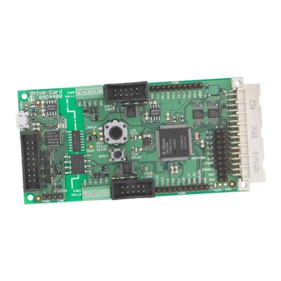
DriveCard XMC4400 (KIT_XMC4400_DC_V1) designed to work with Infineon‟s inverter boards. This board is part of Infineon‟s Motor Control Application Kits. Overview The drive card KIT_XMC4400_DC_V1 houses the XMC4400 Microcontroller from Infineon Technologies, a power board connector, two sets of position interface circuits with hall and encoder connectors, a multi feedback interface and an isolated on-board debug interface with CAN capability. -
Page 8: Block Diagram
Multi Feedback Interface Isolated On-board Debugger via Debug USB connector (Micro-USB) with UART channel (USIC0, channel 0) Optional Infineon Debug interface connector for Drive Monitor USB Stick V2 (KIT_DRIVEMONI_USB_V2) Isolated CAN interface connector at CAN node 0 ENCODER... -
Page 9: Hardware Description
5V debug interface like the drive monitor USB stick (KIT_DRIVEMONI_USB_V2). The debug domain can be powered via the USB plug (5V) as well as the CAN connector or the Infineon debug connector. On the middle to the right side there is the power GND supply domain, which provides the power supply for the MCU and the peripheral components. -
Page 10: Figure 3 Power Supply Concept And Powering Options
Debug Domain Domain IFX1763: 3.3V Linear VDD5: 5V supply via LDO Voltage Regulator Multi Feedback Interface Power indicating Debug USB Connector Infineon Debug Connector Power indicating Power Board 5VISO: 5V supply via Connector CAN Interface Power.emf Figure 3 Power Supply Concept and Powering Options... -
Page 11: Reset
A reset signal connected to the low-active PORST# pin of the target CPU (U201, see Figure 4) can be issued by Potentiometer the on-board Reset Button (SW201, RESET) only. A reset debug command can be issued by the on-board debug device (U401) or an external debugger connected to the Infineon Debug connector. Figure 5 shows the reset button. Reset Potentiometer_LED.emf... -
Page 12: On-Board Usb Debugger
The on-board debugger can be accessed through the Debug USB connector shown in Figure 8. The Debug LED V402 shows the status during debugging. On-board Debug Debugger LEDs Debug USB isolation Connector & UART Infineon Debug Connector isolated transceiver Interface Debugger.emf Figure 8 On-Board USB Debugger Board User's Manual Revision 1.0, 2013-11-05... -
Page 13: Infineon Debug Connector (16-Pin)
2.4.2 Infineon Debug Connector (16-pin) The KIT_XMC4400_DC_V1 board supports debugging via Infineon‟s device access server (DAS), when using KIT_DRIVEMONI_USB_V2 as interface device. The latest release of DAS software can be downloaded from http://www.infineon.com/das. When using an external debugger, the on-board debugger has to be switched off. -
Page 14: Can Interface (X402)
KIT_XMC4400_DC_V1 Drive Card XMC4400 V1 Hardware Description 2.4.3 CAN Interface (X402) The KIT_XMC4400_DC_V1 board provides an isolated CAN interface with 120 termination (see Figure 10 for details). Figure 10 Isolated CAN Interface with Termimation The isolated CAN transceiver (U406) is connected to CAN node 0 of XMC4400 via port pins P14.3 (RX) and P3.2 (TX). -
Page 15: Multifeedback Connectors
KIT_XMC4400_DC_V1 Drive Card XMC4400 V1 Hardware Description Multifeedback Connectors The multifeedback interface can be used as extension to the HALL sensor and encoder interface and provides access to the DSD, USIC, ADC, CCU4, CCU8 and USB peripherals. As a result, a piggy-back board with rotary resolver interface can be easily plugged onto the drive card and extends the functionallity. -
Page 16: Hall Sensor And Encoder Connectors
KIT_XMC4400_DC_V1 Drive Card XMC4400 V1 Hardware Description Hall Sensor and Encoder Connectors The KIT_XMC4400_DC_V1 provides two pairs of HALL and incremental encoder connectors as indicated in Figure 13. The encoder interface connector provides a differential input which is transformed into single ended signals by an interface IC. -
Page 17: Table 4 Hall Sensor And Encoder Interfaces
KIT_XMC4400_DC_V1 Drive Card XMC4400 V1 Hardware Description Table 4 HALL Sensor and Encoder Interfaces Port Peripheral HALL Sensor Interface X303 P1.1 POSIF0.IN2A P14.6 POSIF0.IN1B P14.7 POSIF0.IN0B VDD5 HALL sensor power supply Encoder Interface X301 n.c. VDD5 Encoder power supply n.c. ENCA- POSIF0.IN0B ENCA+... -
Page 18: Power Board Connector
KIT_XMC4400_DC_V1 Drive Card XMC4400 V1 Hardware Description Power Board Connector The KIT_XMC4400_DC_V1 board provides a power board connector with all the signals required to control the power inverter. Next to the PWM output signals of CCU4, CCU8 and HRPWM as well as the ADC signals, there are the power supply pins for the power GND domain. -
Page 19: Table 5 Power Board Connector
KIT_XMC4400_DC_V1 Drive Card XMC4400 V1 Hardware Description Table 5 Power Board Connector X302 Female Function on Port Peripherals Power Inverter MAB32B2 FAB32Q2 PFC Gate P1.3 & (CCU40.OUT0) ERU1.PDOUT0 HROUT10 P0.8 P15.8 & HR.C1INB VADC0.G3CH0 P0.0 P15.9 VADC0.G3CH1 P14.1 VADC0.G0CH1 BEMF_U P14.15 VADC0.G1CH7 G1ORC7... -
Page 20: Table 6 Use Cases Of Pwm Signals
KIT_XMC4400_DC_V1 Drive Card XMC4400 V1 Hardware Description Table 6 Use Cases of PWM Signals X302 (MAB32B2) Function Port Peripheral 2-Level Inverter with CCU80 U0_L P0.2 CCU80.OUT01 U0_H P0.5 CCU80.OUT00 V0_L P0.1 CCU80.OUT11 V0_H P0.4 CCU80.OUT10 W0_L P0.11 CCU80.OUT31 W0_H P0.6 CCU80.OUT30 CTRAP0 P0.7... -
Page 21: Production Data
Hall Sensor and Encoder Interfaces, Power Board Connector Isolated On-board Debugger and CAN Interface The board has been designed with Eagle. The full PCB design data of this board can also be downloaded from www.infineon.com/xmc-dev. Board User's Manual Revision 1.0, 2013-11-05... -
Page 22: Figure 18 Xmc4400 Mcu, Power Supply, Multifeedback Interface
KIT_XMC4400_DC_V1 Drive Card XMC4400 V1 Production Data Figure 18 XMC4400 MCU, Power Supply, Multifeedback Interface Board User's Manual Revision 1.0, 2013-11-05... -
Page 23: Figure 19 Hall Sensor And Encoder Interfaces, Power Board Connector
KIT_XMC4400_DC_V1 Drive Card XMC4400 V1 Production Data Figure 19 Hall Sensor and Encoder Interfaces, Power Board Connector Board User's Manual Revision 1.0, 2013-11-05... -
Page 24: Figure 20 Isolated On-Board Debugger And Can Interface
KIT_XMC4400_DC_V1 Drive Card XMC4400 V1 Production Data Figure 20 Isolated On-board Debugger and CAN Interface Board User's Manual Revision 1.0, 2013-11-05... -
Page 25: Component Placement
KIT_XMC4400_DC_V1 Drive Card XMC4400 V1 Production Data Component Placement X201 X201 Drive Card X305 V301 XMC4400 HALL1 X305 C307 L301 X304 R329 R339 C203 U402 V402 ENC1 C309 C310 X304 R343 R304 L401 C402 C405 V403 R340 R402 U304 U302 R346 U301 C412... -
Page 26: Bill Of Material (Bom)
LEDCHIPLED 0603 LED202, LED203 LED-RT/D/0603 LEDCHIPLED 0603 LED403 32.768KHz CRYSTAL Q201 12MHZ/S/3.2X2.5 CRYSTAL Q202, Q401 FSM16JH SWITCH SW201 BCR198W TRANSISTOR T301, T302, T303, T304 BSS223PW TRANSISTOR T401 BCR148W TRANSISTOR T402 XMC4400_LQFP100 INFINEON MCU U201 Board User's Manual Revision 1.0, 2013-11-05... - Page 27 KIT_XMC4400_DC_V1 Drive Card XMC4400 V1 Production Data IFX1763 INFINEON LDO U202, U402 AD8618ARUZ OPAMP U301, U302 U303, U304 AM26LV32EIPW ENCODER IC XMC4200_QFN48 INFINEON MCU U401 Si8462BB-B-IS1 ISOLATED DIGITAL U405 ISO1050DUB ISOLATED CAN U406 74LVC1G126GW LOGIC U408 SN74LVC2T45DCT LOGIC U409, U410, U411...
- Page 28 . i n f i n e o n . c o m Published by Infineon Technologies AG...
- Page 29 Mouser Electronics Authorized Distributor Click to View Pricing, Inventory, Delivery & Lifecycle Information: Infineon KITXMC4400DCV1TOBO1...
Need help?
Do you have a question about the DriveCard XMC4400 V1 and is the answer not in the manual?
Questions and answers