Chapters
Table of Contents

Related Manuals for Helios EcoVent Verso KWL 45 LE-RS


Summary of Contents for Helios EcoVent Verso KWL 45 LE-RS
- Page 1 Helios Ventilatoren MONTAGE- UND BETRIEBSVORSCHRIFT INSTALLATION AND OPERATING INSTRUCTIONS Laibungselement Rohbauset Soffit element installation kit KWL 45 LE-RS/RSB KWL 45 LE-RP...
- Page 2 Montage- und Betriebsvorschrift Laibungselement Rohbauset KWL 45 LE-RS/RSB / KWL 45 LE-RP DEUTSCH...
-
Page 3: Table Of Contents
Montage- und Betriebsvorschrift Laibungselement Rohbauset KWL 45 LE-RS/RSB / KWL 45 LE-RP Inhaltsverzeichnis KAPITEL 1 SICHERHEIT . . . . . . . . . . . . . . . . . . . . . . . . . . . . . . . . . . . . . . . . . . . . . . . . . . . . . . . . . . . . . . . . . . . . . Seite 4 Wichtige Informationen . -
Page 4: Wichtige Informationen
Medien, längere Stillstandzeiten, starke Verschmutzung, übermäßige Beanspruchung durch klima- tische, technische oder elektronische Einflüsse geeignet. Gleiches gilt für die mobile Verwendung der Lüftungsgeräte (Fahrzeuge, Flugzeuge, Schiffe, usw.). Ein Einsatz unter diesen Bedingungen ist nur mit Einsatzfreigabe seitens Helios möglich, da die Serienausführung hierfür nicht geeignet ist. -
Page 5: Garantieansprüche - Haftungsausschluss
KAPITEL 2 Alle Ausführungen dieser Dokumentation müssen beachtet werden, sonst entfällt die Gewährleistung. Gleiches gilt für Haftungsansprüche an Helios. Der Gebrauch von Zubehörteilen, die nicht von Helios empfohlen oder angeboten ALLGEMEINE HINWEISE werden, ist nicht statthaft. Eventuell auftretende Schäden unterliegen nicht der Gewährleistung. Veränderungen und Umbauten am Gerät sind nicht zulässig und führen zum Verlust der Konformität, jegliche Gewährleistung und Haftung... -
Page 6: Lieferumfang
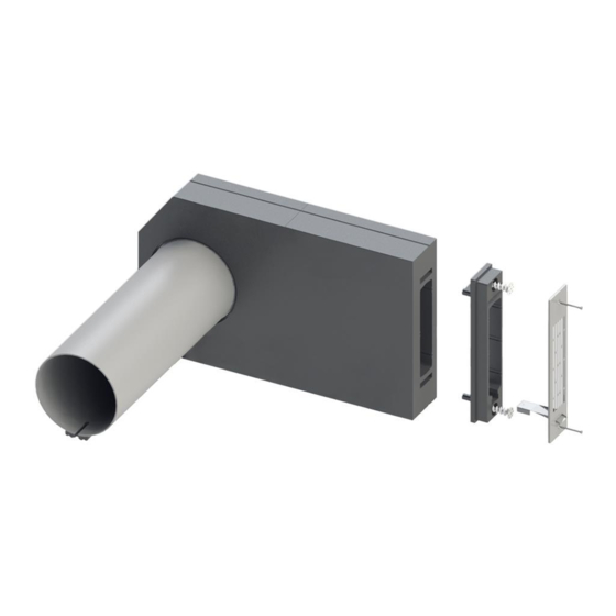
Montage- und Betriebsvorschrift Laibungselement Rohbauset KWL 45 LE-RS/RSB / KWL 45 LE-RP 3 .0 Lieferumfang KAPITEL 3 Das Laibungselement Rohbauset erst unmittelbar vor dem jeweiligen Montageschritt bzw. Einbau aus der Verpackung entnehmen um mögliche Beschädigungen und Verschmutzungen zu vermeiden. LIEFERUMFANG Abb .1 Laibungselement Rohbauset KWL 45 LE-RS... -
Page 7: Einbauübersicht Laibungselement
Montage- und Betriebsvorschrift Laibungselement Rohbauset KWL 45 LE-RS/RSB / KWL 45 LE-RP 4 .0 Einbauübersicht Laibungselement KAPITEL 4 Anforderungen Einbau Laibungselement: POSITIONIERUNG/ 1. Wandstärke der Rohbauwand: mind. 280 mm bis max. 480 mm EINBAU 2. Dämmstärke: Das Laibungselement muss grundsätzlich überdämmt werden. Es ist für Dämmstärken ≤ 100 mm nicht geeignet und darf dort nicht verbaut werden. -
Page 8: Positionierung (Kernbohrung)
Montage- und Betriebsvorschrift Laibungselement Rohbauset KWL 45 LE-RS/RSB / KWL 45 LE-RP SCHNITT A-A Abb . 5 (bis auf 300 mm kürzbar) Innen Aussen Rohbauwand (ohne Dämmung) Wandeinbauhülse Montageschaum Einbaukeil Dichtung auf Wandeinbauhülse Frontkeil für montieren Kondensatgefälle ±3 Leerrohr (Überstand Wandeinbauhülse) 4 .1 Positionierung (Kernbohrung) -
Page 9: Montageschritte Innenwand
Montage- und Betriebsvorschrift Laibungselement Rohbauset KWL 45 LE-RS/RSB / KWL 45 LE-RP Montageschritt INNENWAND: 5. Wandeinbauhülse einkürzen. 6. Wandeinbauhülse mit EPP-Frontkeil bündig zur Innenwand in die Kernlochbohrung einschieben und mittig zum Leerrohr ausrichten (Abb. 7). Stärke des Putz- bzw. Wandbelages beachten! HINWEIS m Die Wandeinbauhülse darf auf der Innenseite nicht eingekürzt werden! 7. - Page 10 Montage- und Betriebsvorschrift Laibungselement Rohbauset KWL 45 LE-RS/RSB / KWL 45 LE-RP 4. Laibungskanal auf die Wandeinbauhülse aufstecken und mit einer Wasserwaage horizontal ausrichten (Abb.12). 5. Bohrpunkte des Laibungskanals übernehmen und den Laibungskanal entfernen. Abb .12 6. Angezeichnete Bohrpunkte bohren und Dübel setzen (nicht im Lieferumfang enthalten). 7.
- Page 11 Montage- und Betriebsvorschrift Laibungselement Rohbauset KWL 45 LE-RS/RSB / KWL 45 LE-RP 10. Umliegende Dämmplatten und Überdämmung anbringen (Abb. 16/17). Das Laibungselement muss grundsätzlich überdämmt werden . Es ist für Dämmstärken ≤ 100 mm nicht geeig- HINWEIS net und darf dort nicht verbaut werden . Abb .16 Abb .17 11.
-
Page 12: Kondensatableitung
Montage- und Betriebsvorschrift Laibungselement Rohbauset KWL 45 LE-RS/RSB / KWL 45 LE-RP 15. Wandgitter montieren (Abb. 21). Die Schrauben sind im Lieferumfang enthalten. Abb .21 Alle nachfolgenden Installationsschritte sind der Montage- und Betriebsvorschrift KWL EC 45 (Druckschrift-Nr . 82 328) zu entnehmen! KAPITEL 5 5 .0 Kondensatableitung... - Page 13 Montage- und Betriebsvorschrift Laibungselement Rohbauset KWL 45 LE-RS/RSB / KWL 45 LE-RP Notizen:...
- Page 14 Installation and Operating Instructions Soffit Element Installation Kit KWL 45 LE-RS/RSB / KWL 45 LE-RP...
- Page 15 Installation and Operating Instructions Soffit Element Installation Kit KWL 45 LE-RS/RSB / KWL 45 LE-RP ENGLISH Table of Contents CHAPTER 1 SAFETY . . . . . . . . . . . . . . . . . . . . . . . . . . . . . . . . . . . . . . . . . . . . . . . . . . . . . . . . . . . . . . . . . . . . . . . Page 4 Important information .
-
Page 16: Chapter 1 Safety
The same applies for the mobile use of fans (vehicles, aircraft, ships, etc.). Usage under these conditions is only possible with release approval from Helios, as the standard version is not suitable in this case. Improper, prohibited use: Any use other than the intended use is not permitted! The conveying of solid matter or solid matter content >... -
Page 17: Chapter 2 General Instructions
CHAPTER 2 All versions of this documentation must be observed, otherwise the warranty shall cease to apply. The same applies to liability claims against Helios. The use of accessory parts, which are not recommended or offered by Helios, is not GENERAL permitted. -
Page 18: Chapter 3 Scope Of Delivery
Installation and Operating Instructions Soffit Element Installation Kit KWL 45 LE-RS/RSB / KWL 45 LE-RP 3 .0 Scope of delivery CHAPTER 3 Leave the soffit element installation kit in its packaging until just before the respective installation step or installation in order to prevent any possible damage and contamination. -
Page 19: Chapter 4 Positioning / Assembly
Installation and Operating Instructions Soffit Element Installation Kit KWL 45 LE-RS/RSB / KWL 45 LE-RP 4 .0 Installation overview soffit element CHAPTER 4 Installation requirements soffit element: 1. Wall thickness of uncovered wall: min. 280 mm to max. 480 mm POSITIONING/ 2. -
Page 20: Positioning (Core Drilling)
Installation and Operating Instructions Soffit Element Installation Kit KWL 45 LE-RS/RSB / KWL 45 LE-RP SCHNITT A-A Fig . 5 (Shortenable to 300mm) (bis auf 300 mm kürzbar) Inside Outside Innen Aussen Uncovered wall Rohbauwand (ohne Dämmung) (without insulation) Wall installation sleeve Wandeinbauhülse Montageschaum Installation foam... -
Page 21: Installation Step Internal Wall
Installation and Operating Instructions Soffit Element Installation Kit KWL 45 LE-RS/RSB / KWL 45 LE-RP Installation step INTERNAL WALL: 5. Shorten wall installation sleeve. 6. Position wall installation sleeve with EPP front wedge flush to the internal wall in the core drill hole and align central- ly with the empty conduit (Fig. - Page 22 Installation and Operating Instructions Soffit Element Installation Kit KWL 45 LE-RS/RSB / KWL 45 LE-RP 4. Connect soffit channel to the wall installation sleeve and align horizontally with a spirit level (Fig.12). 5. Score drilling points for the soffit channel and remove the soffit channel. Fig .12 6.
- Page 23 Installation and Operating Instructions Soffit Element Installation Kit KWL 45 LE-RS/RSB / KWL 45 LE-RP 10. Attach surrounding insulation panels (Fig. 16/17). The soffit element must always be overinsulated . It is not suitable for insulation thicknesses ≤ 100 mm and must HINWEIS not be installed there .
-
Page 24: Chapter 5 Note Condensate Drainage
Installation and Operating Instructions Soffit Element Installation Kit KWL 45 LE-RS/RSB / KWL 45 LE-RP 15. Mount wall grille (Fig. 21). The screws are included in the scope of delivery. Fig .21 All of the following installation steps can be found in the Installation and Operating Instructions KWL EC 45 (Print-No . - Page 25 Installation and Operating Instructions Soffit Element Installation Kit KWL 45 LE-RS/RSB / KWL 45 LE-RP Notes:...
- Page 26 Installation and Operating Instructions Soffit Element Installation Kit KWL 45 LE-RS/RSB / KWL 45 LE-RP...
- Page 27 Installation and Operating Instructions Soffit Element Installation Kit KWL 45 LE-RS/RSB / KWL 45 LE-RP...
- Page 28 HELIOS Ventilatoren GmbH + Co KG · Lupfenstraße 8 · 78056 VS-Schwenningen HELIOS Ventilateurs · Le Carré des Aviateurs · 157 avenue Charles Floquet · 93155 Le Blanc Mesnil Cedex CH HELIOS Ventilatoren AG · Tannstrasse 4 · 8112 Otelfingen GB HELIOS Ventilation Systems Ltd.
Need help?
Do you have a question about the EcoVent Verso KWL 45 LE-RS and is the answer not in the manual?
Questions and answers