
Related Manuals for Honeywell HON 512


Summary of Contents for Honeywell HON 512
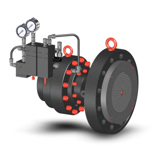
- Page 1 Connected Industrial HON 512 gas pressure regulator with HON 650 pilot User and maintenance manual Spare parts...
-
Page 2: Table Of Contents
Maintaining the actuator assembly - Design 3 Maintaining the pilot 8.4.1 Disassembling the pilot and maintaining the base plate 8.4.2 Maintaining the control stage with a diaphragm assembly 8.4.3 Maintaining the control stage with a larger diaphragm assembly HON 512 with HON 650 pilot user manual... -
Page 3: Maintaining The Actuator Assembly - Design
Appendix 10.1 Additional information regarding spare parts 10.2 Spare parts for HON 512 actuator assembly, design 1, DN 25 – DN 100 10.3 Spare parts for HON 512 actuator assembly, design 2, DN 150 – DN 250 10.4 Spare parts for HON 512 actuator assembly, design 3, DN 25 – DN 250 10.5... -
Page 4: General Considerations
General considerations General considerations Contents Topic Page About this user manual About the safety notices HON 512 with HON 650 pilot user manual... -
Page 5: About This User Manual
About this user manual Validity and purpose This user manual applies to gas pressure regulators consisting of an HON 512 actuator as- sembly combined with an HON 650 pilot. This user manual provides all individuals with the information required for the safe handling in connection with the following tasks: ▪... - Page 6 Constructive changes The written approval from Honeywell Gas Technologies GmbH, Kassel, is required for any modifications and additions to the product. Any violation will void the legal liability for con- sequences arising thereof.
-
Page 7: About The Safety Notices
CAUTION an accident may or will happen. minor or moderate bodily injury. Warnings about material Warnings about possible material damages are identified with the word Attention in this damages document. HON 512 with HON 650 pilot user manual... -
Page 8: Description
Description Description Contents Topic Page Intended use Device models Labels/Markings Identifying the device Layout and operation Assemblies and their function Technical specifications HON 512 with HON 650 pilot user manual... -
Page 9: Intended Use
Intended use Intended use Gas pressure regulators consisting of an HON 512 actuator assembly combined with an HON 650 pilot can be used to maintain the outlet pressure constant within set limits within a gas regulating line regardless of gas discharge changes and inlet pressure changes. These gas pressure regulators work on a purely pneumatic basis. -
Page 10: Device Models
Description Device models Gas pressure Gas pressure regulators consisting of an HON 512 regulator unit combined with an HON 650 pilot are available in a number of versions. These versions are derived from the various regulator versions possible combinations between the various pilot and actuator assembly versions. - Page 11 Description HON 512 actuator as- The HON 512 actuator assembly is available in three different designs: sembly models ▪ Two of the designs are different from each other in terms of their nominal inlet size, and can either include or omit a noise-reducing outlet body.
-
Page 12: Labels/Markings
Nameplates For the location of the nameplates, as well as a detailed list of the information on them and what it means, please refer to: Identifying the device (see page 13) HON 512 with HON 650 pilot user manual... -
Page 13: Identifying The Device
Meaning assembly Name of the device Pressure rating / Flange standard Inlet/outlet nominal size CE specifications Differential pressure (max.) Max. permissible pressure Valve seat diameter Serial number Temperature class Inlet pressure (max.) HON 512 with HON 650 pilot user manual... - Page 14 Interpreting the type The details on the type plate have the following meaning: plate of the pilot Figure Meaning Name of the device Serial number Maximum allowable pressure Controlled variable Specific set range Setpoint HON 512 with HON 650 pilot user manual...
-
Page 15: Layout And Operation
▪ 2-piece body without expander for all pressure ratings ▪ 2-piece body with expander for pres- sure ratings PN 25, PN 40, ANSI Class 300, ANSI Class 600 ▪ Noise-reducing outlet duct in all devices with an expander HON 512 with HON 650 pilot user manual... - Page 16 Description How it works Gas pressure regulators consisting of an HON 512 actuator assembly combined with an HON 650 pilot can be used to maintain the outlet pressure constant within set limits within a gas regulating line regardless of gas discharge changes and inlet pressure changes. Connection lines are used to connect the pilot both to the actuator assembly’s inlet pressure and to the...
-
Page 17: Assemblies And Their Function
Loading pressure gauge fitting (not part of single-stage pilot version) Port for outlet pressure sensing line Port for motorization line Outlet pressure bleed line / return line fitting (back of base plate) Vent line connection HON 512 with HON 650 pilot user manual... - Page 18 ▪ The pilot’s amplifying valve is used to set the speed of the motorization pressure changes. HON 512 with HON 650 pilot user manual...
- Page 19 ▪ The pilot’s two-stage version guarantees a high level of accuracy. ▪ In order to provide protection from soiling, a HON 905 fine mesh filter is installed up- stream of the pilot’s gas inlet. Actuator assembly con- The HON 512 actuator assembly features the following components: figuration Figure Description...
- Page 20 Description Actuator assembly pres- The HON 512 actuator assembly is subdivided into the following pressure sure sections sections: Figure Color Meaning Closed state: Inlet pressure Motorization pressure Outlet pressure Open state: ▪ The diaphragm unit inside the actuator assembly subdivides the inside of the body into...
- Page 21 In order for the actuator assembly to be opened or kept open, the force exerted by the motorization pressure must be greater than the forces opposing it. ▪ The visual position indicator and the optional electrical displacement transducer can be used to read the device’s degree of opening. HON 512 with HON 650 pilot user manual...
-
Page 22: Technical Specifications
Outlet coefficient [m³/h] [m³/h] 19800 14630 16830 2200 37400 1920 25850 1980 30800 5610 41800 5060 250* 25850 8800 30800 7810 55000 39600 46750 *with reduced valve seat diameter of 200 mm HON 512 with HON 650 pilot user manual... - Page 23 (7.9) (0.6) (0.8) (77.2) (3.0) (7.1) (14.2) (0.6) (0.8) (176.4) (3.3) (7.1) (14.2) (0.6) (0.8) (198.4) (10.6) (0.8) (1.0) (154.3) (3.3) (8.7) (16.6) (0.8) (1.0) (286.6) (3.6) (8.7) (16.6) (0.8) (1.0) (330.7) HON 512 with HON 650 pilot user manual...
- Page 24 Nominal size DN ANSI 300 RTJ Inlet Outlet Weight Qty. (in) (in) (in) (in) (in) (lbs) (8.3) (0.8) (1.0) (77.2) (3.0) (7.1) (14.4) (0.8) (1.0) (176.4) (3.3) (7.1) (14.4) (0.8) (1.0) (198.4) HON 512 with HON 650 pilot user manual...
- Page 25 (3.3) (8.7) (16.9) (0.8) (1.0) (286.6) (3.6) (8.7) (16.9) (0.8) (1.0) (330.7) (13.3) (1.0) (1.3) (264.6) (3.9) (10.2) (20.7) (1.0) (1.3) (661.4) (15.5) (1.2) (1.5) (396.8) (4.1) (11.8) (22.0) (1.0) (1.5) (937.0) HON 512 with HON 650 pilot user manual...
- Page 26 (26.0) (2646) Upon request Upon request (29.6) (29.6) Upon request Upon request (5.4) (16.5) (29.6) (29.6) Upon request Upon request (5.8) (16.5) (29.6) (29.6) *with reduced valve seat diameter of 200 mm HON 512 with HON 650 pilot user manual...
- Page 27 (26.0) (2646) Upon request Upon request (29.6) (29.6) Upon request Upon request (5.4) (16.5) (29.6) (29.6) Upon request Upon request (5.8) (16.5) (29.6) (29.6) *with reduced valve seat diameter of 200 mm HON 512 with HON 650 pilot user manual...
- Page 28 The figure below shows the dimensions for the pilot with the control stages for setpoint ranges W = 0.5 – 90 bar: With outlet pressure gauge Without pressure gauge for outlet pressure 1 - 20 bar With outlet pressure gauge 10 - 90 bar Metric system: HON 512 with HON 650 pilot user manual...
- Page 29 2 – 10 bar grey (29 – 145 psi) 5 – 20 bar brown (72.5 – 290 psi) 10 – 40 bar (145 – 580 psi) 10 – 50 bar Green (145 – 725 psi) HON 512 with HON 650 pilot user manual...
- Page 30 M14 x 1.5 The following accuracy class and look-up pressure class apply to gas pressure regulators Accuracy class AC and look-up pressure class SG consisting of an HON 512 actuator assembly combined with an HON 650 pilot. Setpoint range W [bar]...
-
Page 31: Safety
Safety Safety Contents Topic Page Basic safety rules Requirements concerning the workforce, personal protective gear, workplaces HON 512 with HON 650 pilot user manual... -
Page 32: Basic Safety Rules
▪ All personnel must be provided with the personal protective equipment required for their work. This personal protective equipment must be in good condition at all times. ▪ All personnel must wear the personal protective equipment required for their work. HON 512 with HON 650 pilot user manual... - Page 33 The device is designed and built such that the employees can work with it without being at accidents risk. In spite of all the precautions, accidents can happen under unfavorable circumstances. Always consult the directives of your company concerning the protection of the workforce. HON 512 with HON 650 pilot user manual...
-
Page 34: Requirements Concerning The Workforce, Personal Protective Gear, Workplaces
▪ Professional training and experience Tasked with the commis- ▪ Renewed start-up operating pressure equipment and sioning systems ▪ Knowledge of the relevant standards and regulations ▪ Ability to identify and avoid dangers autonomously HON 512 with HON 650 pilot user manual... - Page 35 The workplaces for performing the various tasks are at the following locations: Task Workplaces ▪ Installation All around the device, depending on the task ▪ Start-up ▪ Set-up ▪ Maintenance, repairs ▪ Decommissioning HON 512 with HON 650 pilot user manual...
-
Page 36: Basics For Installing The Device In A Pipe
Basics for installing the device in a pipe Basics for installing the device in a pipe Contents Topic Page Installation examples Meter run characteristics Operating and measuring impulse lines HON 512 with HON 650 pilot user manual... -
Page 37: Installation Examples
- example 2 ▪ Indirect acting gas pressure regulator (pilot-operated) ▪ With expander without noise reduction element downstream of the gas pressure regu- lator ▪ Outlet pressure gauge with protection against overpressure HON 512 with HON 650 pilot user manual... - Page 38 Gas pressure regulator Pilot Safety relief valve Outlet stop valve armature Sensing point for connection lines (gray area) Return line Bleed line Gas pressure regulator measuring impulse line Slam-shut device measuring impulse line HON 512 with HON 650 pilot user manual...
- Page 39 Relief line Blowdown line Following is the meaning of the acronyms: Acr. Meaning Nominal size of pipe Undisturbed length of pipe * Shut-off device with undisturbed flow pattern (ball valve) can be incorporated HON 512 with HON 650 pilot user manual...
-
Page 40: Meter Run Characteristics
A gas pressure regulator with size the same outlet nominal size as The nominal size of the pipe is the inlet nominal size is used two standard nominal size min. 5 x DN increments larger HON 512 with HON 650 pilot user manual... - Page 41 ▪ If shut-off valves are used (reduced bore), the recommended distance downstream of a measuring impulse line is L min. 3 x DN. ▪ Gas meter pressure losses must be taken into account based on system conditions if applicable. HON 512 with HON 650 pilot user manual...
-
Page 42: Operating And Measuring Impulse Lines
On certain devices, the bleed line will be grouped with the return line. ▪ Return line ▪ When using indirect acting (pilot-operated) slam-shut devices, the return line is used to return the outlet pressure to the actuator. HON 512 with HON 650 pilot user manual... -
Page 43: Transport, Installation And Start-Up
Transport, installation and start-up Contents Topic Page Transporting the gas pressure regulator Installing the gas pressure regulator Installing the device connections Checking the system for leaks Starting up the gas pressure regulator HON 512 with HON 650 pilot user manual... -
Page 44: Transporting The Gas Pressure Regulator
▪ The transport route will be able to handle the load exerted by the total weight of the handling equipment and the load being transported. ▪ There is enough space for unpacking and installing the device at the installation loca- tion. HON 512 with HON 650 pilot user manual... - Page 45 Hook the slings (1) into all the eye bolts (2) intended to function as attachment points for transportation. Slowly and carefully lift the device. Slowly and carefully transport the device to the location where it will be installed. HON 512 with HON 650 pilot user manual...
-
Page 46: Installing The Gas Pressure Regulator
(1, 4) and U-sections (2, 5). Remove the fittings (3, 6) and the transport panels (1, 4), including the U-sections (2, HON 512 with HON 650 pilot user manual... - Page 47 Next task Proceed as follows: Installing the device connections (see page 48) HON 512 with HON 650 pilot user manual...
-
Page 48: Installing The Device Connections
Basics for installing the device in a pipe (see page 36) section for more information on what needs to be ensured without fail in the corresponding design and implementation. Install the electrical connection for the op- tional displacement transducer HON 512 with HON 650 pilot user manual... - Page 49 Next task Proceed as follows: Checking the system for leaks (see page 50) HON 512 with HON 650 pilot user manual...
-
Page 50: Checking The System For Leaks
The device has been designed for a specific direction of flow, which is labeled on the device. Subjecting the device to pressure in the wrong direction may result in serious injury caused by bursting parts. Pressurize the system only on the inlet side. HON 512 with HON 650 pilot user manual... - Page 51 ▪ The specifications for the gas pressure regulator in the test setup are the same as the specifications in the inspection certificate. ▪ The blowdown lines (4.7) are sealed with a shut-off device (e.g., ball valve). HON 512 with HON 650 pilot user manual...
- Page 52 (7) in the outlet chamber and then the shut-off device for the blowdown lines (4) in the inlet chamber. Seal the leaking pipe joints. Close the blowdown lines’ shut-off devices. Repeat the leak test starting with step 1. HON 512 with HON 650 pilot user manual...
-
Page 53: Starting Up The Gas Pressure Regulator
▪ The system is depressurized between the inlet shut-off device and the outlet shut-off device. Gas regulating line sche- matic diagram The numbers have the following meaning: Meaning Inlet stop valve armature Gas pressure regulator Outlet stop valve armature HON 512 with HON 650 pilot user manual... - Page 54 Slowly open the outlet shut-off device (3). Monitor the gas pressure regulator’s control behavior for a few minutes. If required, adjust the settings as specified in Adjusting the settings of the device (see page 55). HON 512 with HON 650 pilot user manual...
-
Page 55: Adjusting The Settings Of The Device
Adjusting the settings of the device Adjusting the settings of the device Contents Topic Page Adjusting the loading pressure Adjusting the control stage setpoint Adjusting the amplifying valve HON 512 with HON 650 pilot user manual... -
Page 56: Adjusting The Loading Pressure
▪ Counterclockwise (-) to loosen the pilot spring ▪ Clockwise (+) to tighten the pilot spring Tighten the lock nut (1) to secure the set screw (2) setting. HON 512 with HON 650 pilot user manual... -
Page 57: Adjusting The Control Stage Setpoint
Turn the set screw: ▪ Clockwise (+) to tighten the pilot spring ▪ Counterclockwise (-) to loosen the pilot spring Open the outlet shut-off device. HON 512 with HON 650 pilot user manual... - Page 58 If necessary, keep adjusting the set screw setting until you get the right outlet pressure p Tighten the lock nut (1) to secure the set screw (2) setting. HON 512 with HON 650 pilot user manual...
-
Page 59: Adjusting The Amplifying Valve
(1) out from the sleeve turn by turn while monitoring the actuator assem- bly’s control behavior. As soon as you achieve the actuator assembly response you want, stop changing the spindle’s position. HON 512 with HON 650 pilot user manual... - Page 60 Adjusting the settings of the device Figure Step Description Put the amplifying valve cap back in place. HON 512 with HON 650 pilot user manual...
-
Page 61: Malfunctions
Malfunctions Malfunctions Contents Topic Page Malfunctions HON 512 with HON 650 pilot user manual... -
Page 62: Malfunctions
Perform maintenance on the pilot as specified in Maintaining the pilot (see page 102) Actuator assembly: The diaphragm Perform maintenance on the is defective actuator assembly as specified in the Maintenance (see page 65) section HON 512 with HON 650 pilot user manual... - Page 63 All the reasons why the actuator See above assembly is not closing Sudden outlet pressure Pilot: Not enough amplification Perform maintenance on the pilot drop as specified in Maintaining the pilot (see page 102) HON 512 with HON 650 pilot user manual...
- Page 64 Maintenance (see page 65) section Position indicator: The spring is Perform maintenance on the damaged or not in place position indicator as specified in the Maintenance (see page 65) section HON 512 with HON 650 pilot user manual...
-
Page 65: Maintenance
Maintenance Maintenance Contents Topic Page Maintenance schedule Preparing for the maintenance Maintaining the actuator assembly Maintaining the pilot Completing the maintenance HON 512 with HON 650 pilot user manual... -
Page 66: Maintenance Schedule
Maintenance must be carried out in compliance with all federal and state laws and regula- tions, as well as with the local rules and regulations set forth by the relevant utilities and authorities and any other applicable regulations. HON 512 with HON 650 pilot user manual... -
Page 67: Preparing For The Maintenance
Use the bills of materials to make sure that you replace all the mainte- nance parts relevant to your specific device model during maintenance. If you have trouble understanding the information in this documentation, contact the manu- HON 512 with HON 650 pilot user manual... - Page 68 Maintenance facturer without fail before starting any work on the device. HON 512 with HON 650 pilot user manual...
-
Page 69: Maintaining The Actuator Assembly
Maintaining the actuator assembly Contents Topic Page Maintaining the actuator assembly - Design 1, example with expander Maintaining the actuator assembly - Design 2, example without expander Maintaining the actuator assembly - Design 3 HON 512 with HON 650 pilot user manual... -
Page 70: Maintaining The Actuator Assembly - Design 1, Example With Expander
Device models (see page 10) Refer to the spare parts lists in the appendix (see page 152) to make sure that you replace all the maintenance parts relevant to your device model during maintenance. HON 512 with HON 650 pilot user manual... - Page 71 ▪ Before assembly, all parts must be cleaned in order to remove any foreign particles (swarf) and soiling. ▪ If screws, bolts, or washers are replaced with identical new parts, any oil on these new parts must first be removed. HON 512 with HON 650 pilot user manual...
- Page 72 Removing the Proceed as follows: position indicator Figure Step Description Remove the visual position indicator’s retaining ring (1). Remove the cover ring (1) and the sight glass (2). Remove the magnetic ring (1). HON 512 with HON 650 pilot user manual...
- Page 73 Check the guide ring (3) for damage. Replace it if necessary. Fill the chamber with grease for valve sleeves (as per the lubricant table) via the guide ring. HON 512 with HON 650 pilot user manual...
- Page 74 Take the diaphragm unit. Use the sleeve (3) as a reference. The figure on the left shows the sealing edge (1) facing upwards. This sealing edge features a longer chamfer (2) than the sleeve’s lower edge (4). HON 512 with HON 650 pilot user manual...
- Page 75 Replace the O-ring (2) in the diaphragm plate with a new, greased O-ring and clean the diaphragm unit during the process. Remove the old, used diaphragm (1). HON 512 with HON 650 pilot user manual...
- Page 76 Fold the diaphragm body back to half its height. Place the diaphragm unit back in the inlet body. Make sure that the mounting plate (1) and the screws (2) are facing upwards. HON 512 with HON 650 pilot user manual...
- Page 77 Refer to the additional tightening torque infor- mation at the beginning of this topic. Remove the dummy plug (1) and replace the O-ring (2) with a new, greased one. HON 512 with HON 650 pilot user manual...
- Page 78 Use an open-end wrench to install the guide pin (1) back in place. Place the magnetic ring (1) over the guide pin. The magnetic ring position shown in the figure to the left shows the correct installation height. HON 512 with HON 650 pilot user manual...
- Page 79 Install the retaining ring (1). Maintaining the outlet Proceed as follows: body Figure Step Description Unscrew the screws (1) that connect the two release plates (2, 3) to the outlet body. HON 512 with HON 650 pilot user manual...
- Page 80 2) for the threaded joint at the outlet body are aligned. Take the outlet body. Remove the wire springs (1). Unscrew the relief housing’s socket cap screws (1). Unscrew the studs (1) on the relief hous- ing. HON 512 with HON 650 pilot user manual...
- Page 81 (1), including retaining rings (2), in a criss-cross sequence. Refer to the addi- tional tightening torque information at the beginning of this topic. Screw the studs (1) back into the relief housing. HON 512 with HON 650 pilot user manual...
- Page 82 Tighten the screws (2) in a criss-cross sequence. Refer to the addi- tional tightening torque information at the beginning of this topic. Next task Proceed as follows: Completing the maintenance (see page 141) HON 512 with HON 650 pilot user manual...
-
Page 83: Maintaining The Actuator Assembly - Design 2, Example Without Expander
Device models (see page 10) Refer to the spare parts lists in the appendix (see page 152) to make sure that you replace all the maintenance parts relevant to your device model during maintenance. HON 512 with HON 650 pilot user manual... - Page 84 Set down the actuator assembly on the inlet body (2) in such a way that the position indicator (1) points upwards. Take the assembly’s high center of gravity into account. Secure the assembly’s position. HON 512 with HON 650 pilot user manual...
- Page 85 Remove the cover ring (1) and the sight glass (2). Remove the magnetic ring (1). Use an open-end wrench to unscrew the guide pin (1). Remove the inner pin, including the spring (1). HON 512 with HON 650 pilot user manual...
- Page 86 Check the guide ring (3) for damage. Replace it if necessary. Fill the chamber with grease for valve sleeves (as per the lubricant table) via the guide ring. HON 512 with HON 650 pilot user manual...
- Page 87 Take the diaphragm unit. Unscrew the screws (1) and remove the mounting ring (2). Unscrew the screws (1) on the mounting plate (2). Remove the mounting plate (1) and the diaphragm (2). HON 512 with HON 650 pilot user manual...
- Page 88 Slide the sleeve (2) back into the dia- phragm plate (1). Make sure that the sealing edge is facing upwards. See step 15 for reference. Take a new diaphragm that has not yet been unfolded and grease it. HON 512 with HON 650 pilot user manual...
- Page 89 Place the diaphragm unit back in the inlet body. Make sure that the mounting plate (1) and the screws (2) are facing upwards. Replace the O-ring (1) with a new one. HON 512 with HON 650 pilot user manual...
- Page 90 Take the assembly’s high center of gravity into account. Secure the assembly’s position if necessary. Tighten the screws (1) in a criss-cross sequence. Refer to the additional procedure and tightening torque information at the beginning of this topic. HON 512 with HON 650 pilot user manual...
- Page 91 Use an open-end wrench to install the guide pin (1) back in place. Place the magnetic ring (1) over the guide pin. The magnetic ring position shown in the figure to the left shows the correct installation height. HON 512 with HON 650 pilot user manual...
- Page 92 (1) back on the guide pin. Make sure that the magnetic ring stays in the required position. Install the retaining ring (1). Next task Proceed as follows: Completing the maintenance (see page 141) HON 512 with HON 650 pilot user manual...
- Page 93 The exception are the screws that have a tightening torque specification as per the ta- ble in the Actuator assembly tightening torques section. These screws must be screwed in while still oiled. HON 512 with HON 650 pilot user manual...
- Page 94 Remove the cover ring (1) and the sight glass (2). Remove the magnetic ring (1). Use an open-end wrench to unscrew the guide pin (1). Remove the inner pin, including the spring (1). HON 512 with HON 650 pilot user manual...
- Page 95 Replace the O-rings (1, 2) in the inlet body with new, greased O-rings and clean the inlet body during the process. Check the guide ring (3) for damage and replace it with a new one if necessary. HON 512 with HON 650 pilot user manual...
- Page 96 (4). Unscrew the diaphragm unit screws (1) in a criss-cross sequence. Remove the mounting plate (1) and the diaphragm (2). Replace the O-ring in the mounting plate with a new, greased O-ring. HON 512 with HON 650 pilot user manual...
- Page 97 Slide the sleeve (2) back into the dia- phragm plate (1). Make sure that the sealing edge is facing upwards. See step 8 for reference. Take a new diaphragm that has not yet been unfolded and grease it. HON 512 with HON 650 pilot user manual...
- Page 98 (2) for damage and replace it with a new one if necessary. Use grease for valve sleeves (as specified in the lubricant table) to fill the chamber (1) via the guide ring (2). HON 512 with HON 650 pilot user manual...
- Page 99 When doing so, press down on the plate until the screws are screwed in all the way. Refer to the additional tightening torque infor- mation at the beginning of this topic. HON 512 with HON 650 pilot user manual...
- Page 100 4 The magnetic ring is NOT resting over the guide proceed with step 5. pin in the position shown in step 4, but is instead in a higher or lower position HON 512 with HON 650 pilot user manual...
- Page 101 (1) back on the guide pin. Make sure that the magnetic ring stays in the required position. Install the retaining ring (1). Next task Proceed as follows: Completing the maintenance (see page 141) HON 512 with HON 650 pilot user manual...
-
Page 102: Maintaining The Pilot
Maintaining the control stage with a diaphragm assembly Maintaining the control stage with a larger diaphragm assembly Maintaining the control stage with a metal bellows assembly Maintaining the load limiting stage Maintaining the fine mesh filter Reassembling the pilot HON 512 with HON 650 pilot user manual... -
Page 103: Disassembling The Pilot And Maintaining The Base Plate
(1) and the base plate (2) and remove the control stage. Unscrew the 4 screws (3) between the load limiting stage (1) and the base plate (2) and remove the load limiting stage. HON 512 with HON 650 pilot user manual... - Page 104 Lubricate the thread surfaces before screwing the fittings back in. Remove the cap from the amplifying valve. Unscrew the amplifying valve and remove Loosen the spindle (1) and pull it out towards the back. HON 512 with HON 650 pilot user manual...
- Page 105 Maintaining the control stage with a diaphragm assembly (see page 106) Maintaining the control stage with a larger diaphragm assembly (see page 114) Maintaining the control stage with a metal bellows assembly (see page 125) HON 512 with HON 650 pilot user manual...
-
Page 106: Maintaining The Control Stage With A Diaphragm Assembly
Release the tension on the pilot spring by loosening the hex flange nut (1) and unscrewing the spring adjuster (2) a few turns. Loosen the screws (1) and lift off the upper cover (2). HON 512 with HON 650 pilot user manual... - Page 107 Replace the O-ring (3) in the cap with a new, greased O-ring. Remove the pistons from the connecting piece. Remove the diaphragm disc (1) and the diaphragm (2). HON 512 with HON 650 pilot user manual...
- Page 108 (3) with new ones. When inserting the new diaphragm in place, make sure that it is aligned correctly: The side of the diaphragm that has a depression at the center should be facing upward. HON 512 with HON 650 pilot user manual...
- Page 109 Risk of confusion! Please observe the characterizing difference between the old and the new piston: ▪ Old piston (1): Castellated nut closed ▪ New piston (2): Castellated nut open HON 512 with HON 650 pilot user manual...
- Page 110 Use the cap to turn the diaphragm by hand clockwise until it will not rotate any further. Use a marker or pen to mark the position on the body and on the convoluted dia- phragm. HON 512 with HON 650 pilot user manual...
- Page 111 Lubricate the thread surfaces. Check to make sure that the diaphragm marking is still in the center position (see step 22). Put the cover (2) in place. Tighten the screws (1) hand-tight at first. HON 512 with HON 650 pilot user manual...
- Page 112 Unscrew the adjusting screw (2) and remove it from the base plate. Clean and lubricate the adjusting screw. Replace the hex flange nut (1) with a new one. Lubricate the thread surfaces. HON 512 with HON 650 pilot user manual...
- Page 113 Depending on the specific pilot version, proceed as indicated in the relevant Next task section: For the multi-stage pilot version: Maintaining the load limiting stage (see page 134) For the single-stage pilot version: Maintaining the fine mesh filter (see page 137) HON 512 with HON 650 pilot user manual...
-
Page 114: Maintaining The Control Stage With A Larger Diaphragm Assembly
Figure Step Description Release the tension on the pilot spring by loosening the hex flange nut (1) and unscrewing the spring adjuster (2) a few turns. Unscrew the diaphragm cover’s screws (1). HON 512 with HON 650 pilot user manual... - Page 115 (2) in place so as to prevent the components from turning. Remove the pressure piece (1), the dia- phragm (2), and the diaphragm plate (3). HON 512 with HON 650 pilot user manual...
- Page 116 (2) in place so as to prevent the components from turning. Remove the piston. Remove the diaphragm plate (1) and the diaphragm (2). HON 512 with HON 650 pilot user manual...
- Page 117 (3) with new ones. When inserting the new diaphragm in place, make sure that it is aligned correctly: The side of the diaphragm that has a depression at the center should be facing upward. HON 512 with HON 650 pilot user manual...
- Page 118 Risk of confusion! Please observe the characterizing difference between the old and the new piston: ▪ Old piston (1): Castellated nut closed ▪ New piston (2): Castellated nut open HON 512 with HON 650 pilot user manual...
- Page 119 (1) and the nozzle opening is pointing upwards. Insert the valve insert (2) as far as it will go into the connecting piece (1). Remove the assembly aid. HON 512 with HON 650 pilot user manual...
- Page 120 Place the valve body on the spring housing. Replace the O-ring (1) with a new, greased O-ring. HON 512 with HON 650 pilot user manual...
- Page 121 Observe the tightening torque information provided in the table before this section. Put the spring (1) back in place. HON 512 with HON 650 pilot user manual...
- Page 122 Lubricate the thread surfaces. Screw the screw-in fitting back in. Lubricate the thread surfaces. Tighten the screws (1) in a criss-cross sequence. Observe the tightening torque information provided in the table before this section. HON 512 with HON 650 pilot user manual...
- Page 123 O-ring. Lubricate the thread surfaces. Put the base plate back in place. Tighten the screws in a criss-cross se- quence. Observe the tightening torque information provided in the table before this section. HON 512 with HON 650 pilot user manual...
- Page 124 Depending on the specific pilot version, proceed as indicated in the relevant Next task section: For the multi-stage pilot version: Maintaining the load limiting stage (see page 134) For the single-stage pilot version: Maintaining the fine mesh filter (see page 137) HON 512 with HON 650 pilot user manual...
-
Page 125: Maintaining The Control Stage With A Metal Bellows Assembly
Release the tension on the pilot spring by loosening the hex flange nut (1) and unscrewing the spring adjuster (2) a few turns. Loosen the screws and lift off the upper cover. HON 512 with HON 650 pilot user manual... - Page 126 Remove the lower spring plate (1), the axial washers (2), and the axial needle roller bearing (3) from the spring housing. Remove the compression spring (1) and the upper spring plate (2) from the spring housing. HON 512 with HON 650 pilot user manual...
- Page 127 Unscrew the cap (1) while using an open-end wrench to hold the diaphragm plate (2) in place so as to prevent the components from turning. Replace the O-ring with a new, greased O-ring. HON 512 with HON 650 pilot user manual...
- Page 128 Remove the diaphragm plate (1) and the diaphragm (2). Screw the assembly aid into the valve insert. Pull out the valve insert. Replace the valve insert with a new one. Insert a new, greased O-ring (1). HON 512 with HON 650 pilot user manual...
- Page 129 Observe the tightening torque information provided in the table before this section. Remove the assembly aid (2) from the valve body. Screw the assembly aid (2) into the new valve insert (1). HON 512 with HON 650 pilot user manual...
- Page 130 Use a marker or pen to mark the position on the body. Use the cap to turn the diaphragm by hand so that the marking on the diaphragm is right between the two markings on the body. HON 512 with HON 650 pilot user manual...
- Page 131 Lubricate the upper spring plate’s depres- sions (2). Reinsert the upper spring plate (2) and the compression spring (1) into the spring housing in the right order and alignment. HON 512 with HON 650 pilot user manual...
- Page 132 Lubricate the thread surfaces. Check to make sure that the diaphragm marking is still in the center position (see step 27). Place the upper cover back in place. Tighten the screws hand-tight at first. HON 512 with HON 650 pilot user manual...
- Page 133 Depending on the specific pilot version, proceed as indicated in the relevant Next task section: For the multi-stage pilot version: Maintaining the load limiting stage (see page 134) For the single-stage pilot version: Maintaining the fine mesh filter (see page 137) HON 512 with HON 650 pilot user manual...
-
Page 134: Maintaining The Load Limiting Stage
(see page 106) Turn the load limiting stage. Unscrew the socket cap screws and washers on the base plate Remove the base plate. Replace the O-ring (1) with a new, greased O-ring. HON 512 with HON 650 pilot user manual... - Page 135 Remove the cotter pin (1) from the cap nut. Unscrew the cap nut (1). Unscrew the nut (1). Remove the spring adjuster from the base plate. Replace the O-ring (1) with a new, greased O-ring. HON 512 with HON 650 pilot user manual...
- Page 136 Refer to the additional lubricant and tightening torque information at the beginning of this topic. Next task Proceed as follows: Maintaining the fine mesh filter (see page 137) HON 512 with HON 650 pilot user manual...
-
Page 137: Maintaining The Fine Mesh Filter
Remove the filter insert (1) and clean it. Check the filter cartridge for damage and replace it with a new one if necessary. Replace the O-ring (1) in the body with a new, greased O-ring. HON 512 with HON 650 pilot user manual... -
Page 138: Reassembling The Pilot
(1) with new, greased ones. Install the greased fittings back in place. Observe the tightening torque information provided in the table before this section. Next task Proceed as follows: Reassembling the pilot (see page 139) HON 512 with HON 650 pilot user manual... - Page 139 Tightening torques for Observe the tightening torques below when following the instructions in this section: assembling the pilot Part Tightening torque Step Hex nut 12 Nm (9 ft lbs) 1, 2, 3 HON 512 with HON 650 pilot user manual...
- Page 140 (1) cover and on the load limiting stage (2) cover. Observe the tightening torque information provided in the table before this section. Next task Proceed as follows: Completing the maintenance (see page 141) HON 512 with HON 650 pilot user manual...
-
Page 141: Completing The Maintenance
▪ Air or inert gas as a test medium for the leak test ▪ Foam-generating leakage medium for the leak test Testing the gas pressure regulator for internal leaks HON 512 with HON 650 pilot user manual... - Page 142 Check all spare parts to make sure they are in good condition. Replace any damaged or questionable spare parts. Properly reassemble the gas pressure regulator as indicated in the Maintenance (see page 65) section. Repeat the leak test starting with step 2. HON 512 with HON 650 pilot user manual...
- Page 143 Depending on what you want to do next, proceed as indicated in the relevant section: ▪ Installing the gas pressure regulator (see page 46) ▪ Storing the gas pressure regulator (see page 149) ▪ Disposing of the gas pressure regulator (see page 151) HON 512 with HON 650 pilot user manual...
-
Page 144: Decommissioning, Storage, Renewed Start-Up, Disposal
Decommissioning, storage, renewed start-up, disposal Contents Topic Page Preparing for disassembly Disassembling the device Storing the gas pressure regulator Putting the gas pressure regulator back into operation Disposing of the gas pressure regulator HON 512 with HON 650 pilot user manual... -
Page 145: Preparing For Disassembly
Wait a few minutes so that the pressure in the entire gas pressure regulator (3) can be relieved. Purging the lines with Purge all of the gas pressure regulator’s lines with nitrogen before removing the device. nitrogen HON 512 with HON 650 pilot user manual... - Page 146 When conducting work involving the pipework, please always observe the nections from being following: twisted Figure Description Do not twist the pipe connections in the assemblies. Use a second spanner wrench for securing when loosening and tightening pipe joints. HON 512 with HON 650 pilot user manual...
-
Page 147: Disassembling The Device
▪ The system is depressurized between the inlet shut-off device and the outlet shut-off device. ▪ All the gas pressure regulator’s lines have been purged with nitrogen. ▪ The gas pressure regulator’s electrical connections (electrical displacement transducer, optional) are de-energized and locked and tagged out. HON 512 with HON 650 pilot user manual... - Page 148 Depending on what you want to do next, proceed as indicated in the relevant section: Next task ▪ Maintenance (see page 65) ▪ Storing the gas pressure regulator (see page 149) ▪ Disposing of the gas pressure regulator (see page 151) HON 512 with HON 650 pilot user manual...
-
Page 149: Storing The Gas Pressure Regulator
▪ Storage periods: Check the device for damage and soiling at least annually. When it comes to maintenance cycles, take the preceding operating time into account in addition to the storage time. HON 512 with HON 650 pilot user manual... -
Page 150: Putting The Gas Pressure Regulator Back Into Operation
Check the device with regard to its maintenance condition as indicated in the Maintenance (see page 65) chapter. Put the device back into operation as indicated in the Transport, installation and start-up (see page 43) chapter. HON 512 with HON 650 pilot user manual... -
Page 151: Disposing Of The Gas Pressure Regulator
▪ Recycle elements made of synthetic materials. ▪ Dispose of any other components according to the quality of the materials. HON 512 with HON 650 pilot user manual... -
Page 152: 10 Appendix
Page Additional information regarding spare parts Spare parts for HON 512 actuator assembly, design 1, DN 25 – DN 100 Spare parts for HON 512 actuator assembly, design 2, DN 150 – DN 250 Spare parts for HON 512 actuator assembly, design 3, DN 25 – DN 250... -
Page 153: 10.1 Additional Information Regarding Spare Parts
▪ The required number of maintenance or servicing parts is indicated under the relevant part number in the “Part No.” column. If no quantity is specified, this means that only one unit is required. HON 512 with HON 650 pilot user manual... - Page 154 ▪ Additional list for HON 970a displacement transducer ▪ Spare parts lists for HON 512 actuator assembly, design 2: ▪ Spare parts list for HON 512 actuator assembly, design 2, DN 150 – DN 250 ▪ Additional list for version without expander ▪...
-
Page 155: Spare Parts For Hon 512 Actuator Assembly, Design 1, Dn 25 - Dn
Appendix 10.2 Spare parts for HON 512 actuator assembly, design 1, DN 25 – DN 100 Spare parts drawing for HON 512 actuator assembly, design 1 The top half of the figure shows the version with an expander. The bottom half shows the version without an expander. - Page 156 For DN 80 and DN 100 Version with reverse flow protec- only tion * Item No. not found in all versions. Spare parts list for HON 512 actuator assembly, design 1, DN 25 – DN 100 Name Maint. Part no. DN 25...
- Page 157 Valve scale 10 013 285 10 013 385 10 013 594 10 013 644 Screw plug 10 539 10 539 Sleeve nut 30 805 30 805 Cutting ring 30 904 30 904 HON 512 with HON 650 pilot user manual...
- Page 158 (2 units) (2 units) Socket cap screw 10 324 10 325 10 325 Retaining ring 14 112 14 113 14 113 Spacer pin 10 006 452 10 006 452 10 006 452 HON 512 with HON 650 pilot user manual...
- Page 159 10 394 Retaining ring 14 116 14 116 14 116 Wire spring 26 361 26 361 26 361 (1.8 kg) (3.4 kg) (5.3 kg) Wire spring, stainless 26 362 26 362 26 362 HON 512 with HON 650 pilot user manual...
- Page 160 24 333 24 333 HON 970 displacement transducer 18 353 620 18 353 702 O-ring 20 415 20 415 Socket cap screw 10 349 10 343 Retaining ring 14 123 14 123 HON 512 with HON 650 pilot user manual...
- Page 161 Cable connector 24 158 Washer 14 156 Hex bolt 10 024 Mounting angle bracket 18 361 003 T-nut 101 379 Socket cap screw 10 540 Retaining ring 14 118 Transmitter Upon request HON 512 with HON 650 pilot user manual...
-
Page 162: Spare Parts For Hon 512 Actuator Assembly, Design 2, Dn 150 - Dn
Appendix 10.3 Spare parts for HON 512 actuator assembly, design 2, DN 150 – DN 250 Spare parts drawing for HON 512 actuator assembly, design 2 The top half of the figure shows the version with an expander. The bottom half shows the version without an expander. - Page 163 Visual position indicator section B-B rotated 30° "W" "W" Version with reverse flow protection Version with perforated flow restrictor With reverse flow With expander protection Without expander Without reverse flow protection HON 512 with HON 650 pilot user manual...
- Page 164 Appendix Spare parts list for HON 512 actuator assembly, design 2, DN 150 – DN 250 Name Maint. Part no. DN 150 DN 200 DN 250 Sleeve nut 30 807 30 807 30 807 Cutting ring 30 906 30 906...
- Page 165 10 030 534 Class 600 - B (ANSI 600 RF) 10 026 844 10 026 944 10 030 535 Class 600 - J (ANSI 600RJ) 10 026 845 10 026 945 10 030 536 HON 512 with HON 650 pilot user manual...
- Page 166 18 360 047 10 030 271 O-ring 21 356 21 351 Socket cap screw 10 098 10 441 Spring collar 18 360 048 10 030 272 Compression spring 10 014 961 100 151 HON 512 with HON 650 pilot user manual...
- Page 167 10 026 981 Gasket 10 030 266 10 030 270 Socket cap screw 10 382 10 602 Spring collar 18 360 048 10 030 272 Compression spring 10 014 961 100 151 HON 512 with HON 650 pilot user manual...
- Page 168 10 030 553 Release plate 2 10 030 550 10 030 554 O-ring 21 243 21 365 Socket cap screw 10 556 10 556 Wire springs 26 361 26 361 (21.4 kg) (28.5 kg) HON 512 with HON 650 pilot user manual...
- Page 169 Mounting angle bracket 18 361 003 18 361 003 T-nut 101 379 101 379 Socket cap screw 10 540 10 540 Retaining ring 14 118 14 118 Transmitter Upon request Upon request HON 512 with HON 650 pilot user manual...
-
Page 170: Spare Parts For Hon 512 Actuator Assembly, Design 3, Dn 25 - Dn
10.4 Spare parts for HON 512 actuator assembly, design 3, DN 25 – DN 250 Spare parts drawing for HON 512 actuator assembly, design 3, DN 50 This spare parts drawing is used as an example for design 3 with nominal sizes of DN 25 to DN 100. - Page 171 Appendix Spare parts list for HON 512 actuator assembly, design 3, DN 25 – DN 100: Name Maint. Part no. DN 25 DN 50 DN 80* DN 100 Compression spring 7 X 65 X 58 10013287 10 x 97 x 85...
- Page 172 (8 units) VS 16 14116-RMK 14116-RMK (8 units) (12 units) CIRCLIP NA3555-05S1 19172-RMK 19172-RMK 19172-RMK 19172-RMK RETAINING RING ST5X0.6 19140 19140 19140 19140 SEEGER REINFORCED CIRCULAR SELF-LOCKING 27063-RMK 27063-RMK 27063-RMK 27063-RMK RING KS2.5 HON 512 with HON 650 pilot user manual...
- Page 173 DN50, PN16 10032154 DN50, CLASS150RF 10032155 DN100, PN16 10032120 DN100, CLASS150RF 10032121 Valve body DN25, PN16 10032152 DN25, CLASS150RF 10032153 DN50, PN16 10032156 DN50, CLASS150RF 10032157 DN100, PN16 10032123 DN100, CLASS150RF 10032124 HON 512 with HON 650 pilot user manual...
- Page 174 Fitting EO PSR 10L X 30903 30903 30903 30903 Fitting EO MAVE 10L R1/4 CF 31810 31810 31810 31810 Fitting EO EVGE 10L M14 X 1.5 ED CF 30023 30023 30023 30023 HON 512 with HON 650 pilot user manual...
- Page 175 * Non-listed part numbers for nominal size DN 80 available from the manufacturer upon request. Spare parts drawing for HON 512 actuator assembly, design 3, DN 150 This spare parts drawing is used as an example for design 3 with nominal sizes of DN 150 to DN 250.
- Page 176 Appendix Spare parts list for HON 512 actuator assembly, design 3, DN 150 – DN 250 Name Maint. Part no. DN 150 DN 200 DN 250 Electrical measuring equipment HON 970a for HON 512c DN150-200 10031669 10031669 HON 970a for HON 512c DN250...
- Page 177 EO PSR 16S X 30906 30906 30906 (2 units) O-RING A 22 X 27 18787 18787 18787 Gasket SEALING RING A 14.0 X 20.0 18842-RMK 18842-RMK 18842-RMK (2 units) (2 units) (2 units) HON 512 with HON 650 pilot user manual...
- Page 178 O-RING 2-019 W1.78 D 20.35 20382 20382 20382 (2 units) (2 units) (2 units) Case DN150, PN16 10032126 DN150, CLASS150RF 10032127 DN200, PN16 10032132 DN200, CLASS150RF 10032133 DN250, PN16 10032138 DN250, CLASS150RF 10032139 HON 512 with HON 650 pilot user manual...
- Page 179 GALV. ST35 35505 35505 35505 PIPE 10 X 1.5 GALV. ST35 35505 35505 35505 PIPE 16 X 2 ST35 GALVANIZED 35512 35512 Fitting EO EVW 10L OMD CF 31207 31207 31207 Fitting HON 512 with HON 650 pilot user manual...
- Page 180 (2 units) (2 units) (2 units) Fitting EO PSR 16S X 30906 30906 (2 units) (2 units) Fitting EO VKA 10 CF 32004-RMK 32004-RMK 32004-RMK M20 X 1.5 SCREW PLUG 10539 10539 10539 HON 512 with HON 650 pilot user manual...
- Page 181 18 353 702 O-ring 20 415 20 415 Socket cap screw 10 349 10 343 Retaining ring 14 123 14 123 HON 970a displacement transducer for nominal inlet sizes of DN 80 or greater HON 512 with HON 650 pilot user manual...
- Page 182 Cable connector 24 158 Washer 14 156 Hex bolt 10 024 Mounting angle bracket 18 361 003 T-nut 101 379 Socket cap screw 10 540 Retaining ring 14 118 Transmitter Upon request HON 512 with HON 650 pilot user manual...
-
Page 183: 10.5 Spare Parts For Two-Stage Hon 650 Pilot
10.5 Spare parts for two-stage HON 650 pilot Spare parts drawing for pilot with metal bellows assembly Without pressure gauge p X: Fail-to-open version With pressure gauge p Y: Amplifying valve 20 to 90 bar HON 512 with HON 650 pilot user manual... - Page 184 Spare parts drawing for pilot with diaphragm assembly Without pressure gauge p With pressure gauge With pressure gauge and HON 925 without HON 925 0.5 to 20 bar 10 to 40 bar HON 512 with HON 650 pilot user manual...
- Page 185 Appendix X: Fail-to-open version Y: Amplifying valve HON 512 with HON 650 pilot user manual...
- Page 186 Appendix Spare parts drawing for pilot with larger diaphragm assembly Without pressure gauge p X: Fail-to-open version With pressure gauge p and HON 925 Y: Amplifying valve 0.3 to 1 bar HON 512 with HON 650 pilot user manual...
- Page 187 Appendix Spare parts drawing for pilot with diaphragm assembly for pneumatic follow-up setpoint value Y: Amplifying valve HON 512 with HON 650 pilot user manual...
- Page 188 (8 units) (7 units) Retaining ring 19 065 19 065 19 065 19 065 O-ring 20 283 20 283 20 283 20 283 O-ring 20 332 20 332 20 332 20 332 HON 512 with HON 650 pilot user manual...
- Page 189 Appendix Spare parts drawing for load limiting stage HON 512 with HON 650 pilot user manual...
- Page 190 10 000 088 Spring housing 10 000 071 Spring housing when used as control stage 10 000 087 Plate, pre-assembled 10 010 480 Plate, pre-assembled, when used as control stage 10 010 080 HON 512 with HON 650 pilot user manual...
- Page 191 Spare parts drawing for The left half of the figure shows the standard design without an electric actuator. The right control stage with metal half shows the version with the electric actuator installed. bellows assembly HON 512 with HON 650 pilot user manual...
- Page 192 ▪ W = 20-90 bar 10 010 444 Spring plate for the following specific setpoint ranges: ▪ W = 10-50 bar 19 084 400 ▪ W = 20-90 bar 10 011 774 HON 512 with HON 650 pilot user manual...
- Page 193 Spare parts drawing for The left half of the figure shows the standard design without an electric actuator. The right control stage with dia- half shows the version with the electric actuator installed. phragm assembly HON 512 with HON 650 pilot user manual...
- Page 194 ▪ W = 1-5 bar 10 009 671 ▪ W = 2-10 bar 10 000 139 ▪ W = 5-2 bar 10 000 115 ▪ W = 10-40 bar 10 000 064 HON 512 with HON 650 pilot user manual...
- Page 195 Spare parts for control The left half of the figure shows the standard design without an electric actuator. The right stage with larger dia- half shows the version with the electric actuator installed. phragm assembly HON 512 with HON 650 pilot user manual...
- Page 196 (4 units) Piston, pre-assembled 10 000 186 O-ring 20 225 Valve insert 10 000 061 O-ring 20 293 Servicing parts Name Part no. Spring collar 10 000 114 Compression spring 10 000 156 HON 512 with HON 650 pilot user manual...
- Page 197 Spare parts drawing for HON 905 fine mesh filter Maintenance parts Name Part no. Gasket 18 842 (2 units) O-ring 20 317 O-ring 20 282 Servicing parts Name Part no. Filter insert 26 183 HON 512 with HON 650 pilot user manual...
-
Page 198: 10.6 Spare Parts For Single-Stage Hon 650-1 Pilot
10.6 Spare parts for single-stage HON 650-1 pilot Spare parts drawing for single-stage pilot with metal bellows assembly Without pressure gauge p X: Fail-to-open version With pressure gauge p Y: Amplifying valve 20 to 90 bar HON 512 with HON 650 pilot user manual... - Page 199 Spare parts drawing for single-stage pilot with diaphragm assembly Without pressure gauge p With pressure gauge p With pressure gauge p without HON 925 HON 925 0.5 to 20 bar 10 to 40 bar X: Fail-to-open version Y: Amplifying valve HON 512 with HON 650 pilot user manual...
- Page 200 Appendix Spare parts drawing for single-stage pilot with larger diaphragm assembly Without pressure gauge p X: Fail-to-open version With pressure gauge p and HON 925 Y: Amplifying valve 0.3 to 1 bar HON 512 with HON 650 pilot user manual...
- Page 201 The spare parts for the three different control stage versions and the spare parts for the fine stage and fine mesh filter mesh filter are listed in the “Spare parts for two-stage HON 650 pilot” section. HON 512 with HON 650 pilot user manual...
-
Page 202: 10.7 Lubricants, Threadlockers, And Tools
Important! All parts must be coated slightly. Use the following threadlockers: Application Threadlocker Part no. For the HON 650 pilot ▪ Cap threads LOCTITE 26 688 ▪ Hex nut threads ▪ Connecting piece threads HON 512 with HON 650 pilot user manual... - Page 203 ▪ DN 50 nominal inlet size Special top piece 26 706 ▪ DN 80 nominal inlet size Special top piece 27 078 ▪ DN 100 nominal inlet size Special top piece 27 078 HON 512 with HON 650 pilot user manual...
-
Page 204: 10.8 Technical Specifications For Hon 970A Electrical Displacement Transducer
Appendix 10.8 Technical specifications for HON 970a electrical displacement transducer HON 512 with HON 650 pilot user manual... - Page 205 Appendix HON 512 with HON 650 pilot user manual...
- Page 206 Appendix HON 512 with HON 650 pilot user manual...
- Page 207 Appendix HON 512 with HON 650 pilot user manual...
- Page 208 Subject to change without notice Additional information To learn more about Honeywell’s solutions for the gas industry, contact your local contact person or visit our website at www.honeywellprocess.com. Honeywell Process Solutions Honeywell Gas Technologies GmbH Osterholzstrasse 45 34123 Kassel, Germany...
Need help?
Do you have a question about the HON 512 and is the answer not in the manual?
Questions and answers