Intec FORCE/2 Instruction Manual
Hide thumbs
Also See for FORCE/2:
- Installation instructions manual (11 pages) ,
- Instruction manual (21 pages) ,
- Instruction manual (16 pages)

Related Manuals for Intec FORCE/2


Summary of Contents for Intec FORCE/2
- Page 1 Instruction Manual 3771 Monarch Street • Frederick, CO 80530 • www.inteccorp.com Local: (303) 833-6644 • Fax: (303) 833-6650 • Toll Free: (800) 666-1611...
-
Page 3: Table Of Contents
THE FORCE/2 T able of Contents Machine Information ................2 Contacting Intec ................3 Introduction..................4 Specifications..................5 Overview ....................6 How the System Works Together ............9 Safety First ..................11 Set-Up and Operation ..............12 Operational Guidelines ..............15 Sidewall & Insulation Material ............16 Generators and Extension Cords ..........18 Maintenance ..................19... -
Page 5: Contacting Intec
United States visit our web site, www.inteccorp.com and go to service centers. All service centers are independently owned and operated and are not part of Intec. Consult the nearest service center for the hours of operation and lead time for repair. - Page 6 It is designed and built to blow-in more than a ton of material per hour. No other machine in its class can match the performance of the FORCE/2. Because no insulation goes through the blower, the FORCE/2 is a virtual workhorse, requiring only minimal maintenance. The direct drive feature also means there are no chains for you to adjust or replace, ever.
-
Page 7: Specifications
THE FORCE/2 Specifications Height 45" without wheels ⁄ " with wheels Width 32" Weight 283 lbs. without wheels 302 lbs. with wheels Hopper Capacity 50 lbs. Hose Size 3" Blower, 2-stage 105 CFM, 3.6 PSI (AVG) 11.5 amps 116 CFM, 4.5 PSI (AVG) 12.5 amps (Optional) Agitator Motor ⁄... -
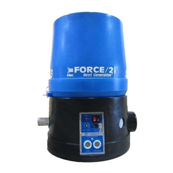
Page 8: Overview
THE FORCE/2 Overview Variable Speed Main Panel Bypass Switch Switches Remote Control Variable Receptacle Speed Control Agitator Motor Circuit Breaker Flange Receptacle (Power Cord) Remote Switch Blower/ Agitator Fiberglass Bale Breaker (Optional) Agitator... - Page 9 (See next page for drawings.) SYSTEM COMPONENTS. A. Hopper: Upper component of the FORCE/2 where insulation is loaded. B. Base: Lower component of the FORCE/2 houses power components, agitator motor, blower, gearbox, airlock and electrical system.
- Page 10 THE FORCE/2 Overview, Cont. Remote Cord Example only see page 35 for specific electrical systems.
-
Page 11: How The System Works Together
AIRLOCK: the air flow from the blower. Airlock seals must be inspected regularly and kept in good working order for the FORCE/2 to operate efficiently. We recommend changing the airlock seals every 300 hours, 200,000 pounds of insulation or once a year, whichever comes first. - Page 12 THE FORCE/2 How the System W orks T ogether , Cont. REMOTE CONTROL: Permanently attached to the main panel, the remote control cord allows the operator to control the machine’s on/off function from the attic. Both the agitator and the...
-
Page 13: Safety First
THE FORCE/2 Safety First When working with insulation, always wear a long sleeve shirt, gloves, a hat, goggles or safety glasses for eye protection and a 3M brand #8710 nose/mouth filter (or equivalent) for respiratory protection. ACCESSORIES YOU NEED TO WEAR... -
Page 14: Set-Up And Operation
Operate the blower and agitator from the main electrical panel toggle switches. Note: In cold weather, your machine is more difficult to start. If possible, store your FORCE/2 in a warm area over-night before starting this helps ensure the lubricant (oil) is warm, enabling the bearings and gearbox to turn freely. - Page 15 Following the instructions in this manual along with good common sense, should allow you to complete your job in a safe and efficient manner. First, before loading your FORCE/2, follow all safety considerations provided by the manufacturer of the insulation material you are using, including wearing protective masks or respirators.
- Page 16 Cellulose, place the bag of insulation material on the hopper. Use a knife to open the bag so that the material falls into the hopper. Your FORCE/2 is designed to self-feed. Fiberglass, place the bag on the side of the hopper. Cut the bag in thirds and dispense one third of the contents gradually until the agitator breaks up and conditions the material.
-
Page 17: Operational Guidelines
THE FORCE/2 Operational Guidelines BLOWING SIDEWALLS, CELLULOSE: When blowing sidewalls, use the following settings and recommendations as guidelines. Settings may change from job to job, material to material, or nozzle to nozzle. Hose length and humidity may affect your results. -
Page 18: Sidewall & Insulation Material
THE FORCE/2 Sidewalls & Insulation Material Construction example: 2 inches x 4 inches x 8 feet on 16 inch centers, 2.8 cubic foot cavity CELLULOSE COVERAGE: US Greenfiber Customer Support 800-228-0024 US Greenfiber, Cocoon 22.5lb bag Wall Pack Density Pounds Per Cavity 2.6 PCF @ R13... - Page 19 Your Force/2 can apply both wall-spray and spray-on materials. There are many different types of material for these applications and depending upon the material your results will differ. The Force/2 has been designed to apply most materials and can recycle up 75/25 blend of Dry/Wet cellulose material. Using recycled material will change the speed of the material traveling through the hose and will change the impact (density) of the wall area being sprayed.
-
Page 20: Generators And Extension Cords
FORCE/2 and protect the generator. The start-up requirement for a FORCE/2 is 9660 watts; normal operating requirement is 3300 watts. We recommend a generator of not less than 9000 watts, 120 VAC. In addition, Intec recommends generators that have a 50% power boost feature which aids the generator in high current startups. -
Page 21: Maintenance
Repair or replace any damaged components at once to avoid possible injury. AIRLOCK BLOW BACK Airlock seals are the most important component of keeping your FORCE/2 running in original condition. Airlock seals function much like the rings in a car engine, keeping pressure and air from escaping. - Page 22 We recommend changing the airlock seals every 300 hours, 200,000 pounds of insulation or once a year, whichever comes first. Unplug the FORCE/2 from electrical power and empty all insulation material from the hopper. Seal replacement requires a 7/16" socket and ratchet, a 6"...
- Page 23 THE FORCE/2 Maintenance, Cont. GEARBOX The oil in the gearbox of your FORCE/2 should be changed every year to ensure proper lubrication of the gears and seals. Changing oil in all direct drive models: Model 22015 Model 22015 Place the machine on its side with clear access to the two drain/fill plugs on the gearbox.
- Page 24 THE FORCE/2 Maintenance, Cont. Recommended gearbox oil: Model 22014 Capacity: 48 oz. Temperature 40˚ - 100˚ F Mobil SHC 634 gear lube Temperatures -20˚ - +40˚ F Mobil 1 synthetic 5W-30 Model 22014 Vent Plug ⁄ ⁄ Turn to Vent Drain &...
- Page 25 Overheating will cause lowered production, possible system failure and shorten the expected life of your FORCE/2. Inspect blower brushes every three months or 100 hours of use. Replace brushes when they reach ⁄...
- Page 26 THE FORCE/2 Maintenance, Cont. REPLACING BLOWER BRUSHES Model 21025 (105 CFM) brush replacement not recommended Model 21024 (116 CFM) shown Removing old brushes: Disconnect all electrical cords to machine. Tip machine upside down onto hopper. To facilitate replacement of the blower brushes remove blower from machine.
-
Page 27: Troubleshooting
THE FORCE/2 T roubleshooting Problem Likely Cause Remedy Agitator does not Power cords Check cord operate. not plugged in. and plug in. Note: Agitator can Loose power cord/ Check condition of not be turned extension cord at electrical plug blades. - Page 28 THE FORCE/2 T roubleshooting, Cont. Problem Likely Cause Remedy Machine makes a Gearbox drive not Loosen gearbox and grinding noise when engaged with airlock gearbox stabilizers. Align running. rotor connection out gearbox and airlock shaft of alignment. perpendicular to each other.
- Page 29 THE FORCE/2 T roubleshooting Cont. Problem Likely Cause Remedy Machine does not run Main panel circuit Wait for a few minutes, Cont. breaker tripped. push to reset. Air, but no material, Slide gate closed. Open to operating comes out of hose position.
- Page 30 Remove blown fuse and replace with 15 amp AG style fuse. Agitator trips circuit Low voltage 99-104v. FORCE/2 requires a breaker at main minimum of 20 amps panel. @ 115V. Relocate power cord to a dedicated 20 amp circuit.
-
Page 31: Mechanical Drawings
THE FORCE/2 Mechanical Drawings Fiber Glass Hopper 22000 22141 Slide Gate Guide 22000-06 & 22000-07 Agitator 22025 Slide Gate 22000-03 Slide Gate Pin 22000-04 Base Airlock Seal 22013 22004 22004-01 Airlock Rotor 22008 without seals Blower 21024 21025 3" Hose... - Page 32 (Mfg from 8/02-12/06) 1..21000-05-S 25..22042-01-S AIRLOCK ASSM. W/BEARINGS ELECTRICAL SYSTEM ASSM. & SS INSERTS 2..21025-S ..BLOWER, 2 STG, 115V, 60 Hz, 26..22053-02 AGITATOR MOTOR SUPPORT BRACE 105 CFM, ASSM. 27..22131..AIRLOCK GASKET 3..21024-S ..BLOWER, 2 STG, 115V, 60 Hz, 28..F101..3/8 x 16 x 2-1/4" CAPR. ZN 116 CFM, ASSM.
- Page 33 3 ..21024-S ..BLOWER, 2 STG 115 V, 60HZ, SUPPORT BRACE 116 CFM, ASSM. 4 ..21026-S ..Agitator motor assm., 1.5 HP 28 ..22106 ..SERIAL TAG FORCE/2 29 ..22131 ..AIRLOCK GASKET 115/220V, 60 HZ 30 ..F101 ..3/8*16 X 2-1/4" CARRIAGE ZN 4A..21027-S ..Agitator motor assm., 2.0 HP 31 ..F103 ..3/8*16 X 1-1/2"...
- Page 34 Airlock Assembly Item # PART NUMBER DESCRIPTION 1 ..22005-02 ....AIRLOCK INLET PLATE ASSM. 2 1/2" 2 ..22005-09 ....AIRLOCK TUBE 12" (CRS) 3 ..22005-01 ....AIRLOCK OUTLET PLATE ASSM. 3" 4 ..22021 ....AIRLOCK BEARING FLANGE 4 HOLE 5 ..22008 ....AIRLOCK ROTOR ASSEMBLY W/O SEAL 6 ..22013 ....AIRLOCK SEAL 7 ..22116 ....AIRLOCK WEAR WASHER 8 ..F221....CAGE NUT ZN...
- Page 35 Airlock Rotor Item # PART NUMBER DESCRIPTION 1 ..22008 ..AIRLOCK ROTOR ASSM. W/O SEALS 2 ..22013....AIRLOCK SEAL 3 ..22116 ....WEAR WASHER NYLON 5/8" 4 ..F112 ....1/4*20x7/8 GRADE 5 HEX HEAD ZN 5 ..F114 ....1/4*20 NYLON LOCKNUT ZN...
- Page 36 Model 21024 116 CFM Blower Item # PART NUMBER DESCRIPTION 1 ..21025....BLOWER 2 STG., 115V, 60 Hz, 105 CFM 1 ..21024....BLOWER 2 STG., 115V, 60 Hz, 116 CFM n/a ..21025-05 ..Blower Brush (set of two) 2 ..22022--..BLOWER MOUNTING BRACKET 3 ..22022-01 ..BLOWER MOUNTING BRACKET 6-3/4" 4 ..F112 ....1/4*20 X 7/8"...
- Page 37 Electrical without GFCI Mfg from 7/89 - 9/02 Item # PART NUMBER DESCRIPTION 1 ..R22001-02 ..ELECTRICAL BOX W/HOLES 2 ..21012-00-S ..REMOTE CORD 18/7 x 100' COMP. W/RS & VSC 3 ..21016-S..ELECTRICAL PANEL ASSM. 4 ..21002....TRANSFORMER 110 VOLT 5 ..21003-02 ..ELECTRICAL CONTACTOR (2 HP) 6 ..21003-03 ..ELECTRICAL CONTACTOR MOUNT RAIL 7 ..21017-02 ..FUSE HOLDER, BLOWER 8 ..21019 ....ELECTRICAL BOX FLANGE CONNECTOR...
- Page 38 Electrical without GFCI Mfg from 7/89 - 9/02 Item # PART NUMBER DESCRIPTION 1 ..11072 ....REMOTE BOX TOGGLE SWITCH SEAL 2 ..21000-02-S ..ROCKER SWITCH, PANEL 3 ..21008-02 ..STRAIN RELIEF, ALUM. 1/2" 4 ..21010 ....ELECTRICAL FLANGE RECEPTACLE TWIST 15 AMP 5 ..21016-0 ..ELECTRICAL FACE PLATE “STD” 1996 W/SILK SCREEN 6 ..21045-01 ..CIRCUIT BREAKER 20 AMP 7 ..21045-02 ..CIRCUIT BREAKER BUTTON SEAL 8 ..21143-07..VARIABLE SPEED BYPASS SWITCH...
- Page 39 Electrical without GFCI Mfg from 7/89 - 9/02 Item # PART NUMBER DESCRIPTION 1 ..21008-0 ..REMOTE BOX 3/4 W/HOLE 2 ..21008-09 ..STRAIN RELIEF, ALUMINUM, 3/4" 3 ..21008-10 ..REMOTE CORD 18/7 X 100' (ONLY) 4 ..21008-12 ..REMOTE BOX CONNECTOR SOCKET MALE 5 ..21008-13 ..REMOTE BOX CONNECTOR SOCKET FEMALE 6 ..21008-14 ..REMOTE BOX CONTACT PIN MALE 7 ..21008-15 ..REMOTE BOX CONTACT PIN FEMALE...
- Page 40 Wiring Diagram Mfg from 7/89 - 9/02 Electrical with Variable Speed Control in Remote Cord...
- Page 41 Electrical with GFCI Mfg from 8/02 - Present Item # PART NUMBER DESCRIPTION 1 ..R22001-02 ..ELECTRICAL BOX W/HOLES 2 ..21006-S ..REMOTE CORD 18/4 x 100' ASSM. 3 ..21016-02-S ..ELECTRICAL PANEL ASSM. 4 ..21002....TRANSFORMER 110 VOLT 5 ..21003-02 ..ELECTRICAL CONTACTOR (2 HP) 6 ..21003-03 ..ELECTRICAL CONTACTOR MOUNT RAIL 7 ..21017-02 ..FUSE HOLDER, BLOWER 8 ..21019 ....ELECTRICAL BOX FLANGE CONNECTOR...
- Page 42 Electrical with GFCI Mfg from 8/02 - Present Item # PART NUMBER DESCRIPTION 12..F119 ....8-32X3/8 PP ZN 13..F223....10-32X5/8 FIL TRUSS ZN 14..21000-02 ..ROCKER SWITCH, PANEL 15..21008-02 ..STRAIN RELIEF, ALUM. 1/2" 16..21010 ....ELECTRICAL FLANGE RECEPTACLE, TWIST 15 AMP.34 21016-03 ....ELECTRICAL FACE PLATE "OC" W/SILK SCREEN 18..21045-01 ..CIRCUIT BREAKER 20 AMP.
- Page 43 Remote Box Assembly Electrical with GFCI Mfg from 8/02 - Present Electrical without GFCI Mfg from 7/89 - Present Item # PART NUMBER DESCRIPTION 22 ..21008-0 ..REMOTE BOX 3/4" W/HOLE 23 ..21008-09 ..STRAIN RELIEF, ALUM. 3/4" 24..21008-03 ..REMOTE CORD 18/4X100' (ONLY) 25 ..01009....REMOTE BOX 31"...
- Page 44 Electrical with GFCI Mfg from 8/02 - Present VERSION A Item # PART NUMBER DESCRIPTION 1 ..22001-03 ..ELECTRICAL BOX W/CURVE, WHOLES 2 ..21002....TRANSFORMER 110 VOLT 3 ..21003-02 ..ELECTRICAL CONTACTOR (2 HP) 4 ..21003-03 ..ELECTRICAL CONTACTOR MOUNT RAIL 5 ..21017-02 ..FUSE HOLDER, BLOWER 6 ..21019 ....ELECTRICAL BOX FLANGE CONNECTOR 7 ..21020-01 ..ELECTRICAL BOX MOUNTING PLATE 1/8 X 5 X 6-3/8 8 ..21025-07 ..FUSE, 15 AMPS...
- Page 45 Electrical with GFCI Mfg from 8/02 - Present VERSION B Item # PART NUMBER DESCRIPTION 1 ..R22001-02 ..ELECTRICAL BOX W/ HOLES 2 ..21002....TRANSFORMER 110 VOLT 3 ..21003-02 ..ELECTRICAL CONTACTOR (2 HP) 4 ..21003-03 ..ELECTRICAL CONTACTOR MOUNT RAIL 5 ..21017-02 ..FUSE HOLDER, BLOWER 6 ..21019 ....ELECTRICAL BOX FLANGE CONNECTOR 7 ..21020....ELECTRICAL BOX MOUNTING PLATE 8 ..21025-07 ..FUSE, 15 AMPS...
- Page 46 Wiring Diagram Manufactured from 8/02 - Present Electrical with GFCI...
- Page 47 Electrical with Remote Disconnect Mfg from 9/02 - Present Item # PART NUMBER DESCRIPTION 1 ..21006-S ..REMOTE CORD/BOX 18/4X100' ASSM. (see page 41 for more detailed remote cord drawings) 2 ..11072 ....REMOTE BOX TOGGLE SWITCH SEAL 3 ..21000-03 ..ROCKER SWITCH, BLACK 4 ..21000-04 ..ROCKER SWITCH, RED 5 ..21000-02 ..ROCKER SWITCH PANEL 6 ..21010 ....ELEC.
- Page 48 Electrical with Remote Disconnect Mfg from 9/02 - Present Item # PART NUMBER DESCRIPTION 14..21003-02 ..ELECTRICAL CONTACTOR 2 HP 15..21003-03 ..ELECTRICAL CONTACTOR MOUNT RAIL 16..21143-06 ..VARIABLE SPEED CONTROL 17..21002....TRANSFORMER 110/24 VAC 18..21020....ELECTRICAL BOX MOUNTING PLATE 19..R22001-02 ..ELECTRICAL BOX W/HOLES 20 ..21025-07 ..FUSE, 15 AMP 21..21017-02 ..FUSE HOLDER 22 ..21019 ....ELECTRICAL BOX FLANGE CONNECTOR 23 ..F119 ....#-32x3/8"...
- Page 49 Wiring Diagram Mfg from 9/02 - Present Electrical With Remote Disconnect...
-
Page 51: Electrical Drawings
FORCE/2 Electrical Drawings (Cont’d) Electrical Wiring Diagram with Variable speed control and Remote disconnect Mfg. from 1/2011 - Present... - Page 52 FORCE/2 Electrical Drawings (Cont’d) ...
- Page 53 FORCE/2 Electrical Drawings (Cont’d) Item # QTY. PART NUMBER DESCRIPTION 1....1.....21008-03....Remote Cord 18/4 x 100’ 2....1.....21050....Remote Box, 3/4”, Molded 3....1.....21051....Remote, Box Shield, 3/4” Molded 4....1.....21061....Switch Assm, Field Replacement Remote Box Molded 5....2.....11072....Remote Box Toggle Switch Seal 6....2.....F119.....8*32 x 3/8” Screw 7....1.....21021....Remote Disconnect Plug Male...
-
Page 54: Claims, Damage Or Loss
THE FORCE/2 Claims, Damage or Loss These goods were carefully packed and thoroughly inspected before leaving our factory. Responsibility for its safe delivery was assumed by the carrier upon acceptance of the shipment. Inspect shipment carefully on the arrival for damage to contents, shortages or equipment. - Page 55 If you have any questions regarding the above information please feel free to contact an INTEC representative. RETURNS We at INTEC sincerely hope the merchandise you have just received is in excellent condition and satisfies your expectations. If not, please look below and follow the instructions which apply to your particular situation.
-
Page 56: Returns
THE FORCE/2 Returns SHIPMENTS TO FACTORY All shipments to the factory must have a RMA number on the outside of the carton. You will be given a RMA number when you contact the Sales Department. The RMA is the only way to track and assure that your request is handled properly. If you received an invoice with your merchandise, please include a copy of the invoice with all returned materials. -
Page 57: Receiving Replacement Parts
We will issue a Return Merchandise Authorization (RMA) number and instructions to return the defective part. All shipments to INTEC must be sent via UPS, except in the case of complete machines, when a common carrier should be used. -
Page 58: Warranty
It is expressly understood and agreed that no officer, agent, salesman or employee of the Manufacturer INTEC has the authority to obligate the Manufacturer by any terms, stipula- tions, or conditions not herein expressed; that all previous representations and agreements, either... -
Page 59: Insulation Terms And Values
All blown insulation will settle after installation. Your SETTLEMENT: FORCE/2 installs near settled density. Consult the chart on the material bag for coverage and install accordingly. : Every bag of material comes with a coverage chart COVERAGE detailing R-Value ratings. - Page 60 THE FORCE/2 Insulation T erms and V alues, Cont. COMMON INSULATION VALUES Material Thickness R-Value Air Space 1" 1.01 Cellulose loose fill 1" 3.70 Celotex 1" 3.03 Concrete block 8", hollow 1.11 Fiberglass batt ⁄ " 11.0 Fiberglass batt 8"...
Need help?
Do you have a question about the FORCE/2 and is the answer not in the manual?
Questions and answers
Trying to connect the end piece of a force to insulation blower remote rewiring it and could use instructions on which color goes into which positive and negative Port
The Intec FORCE/2 insulation blower remote uses 24V AC power, not DC, so there are no positive and negative ports. Instead, it uses two wires for completing the AC circuit.
To connect the remote end piece correctly:
1. The transformer converts 120V AC to 24V AC.
2. One wire from the transformer goes to contact A2 on the contactor.
3. The remote uses a cord (part #21006-S) with multiple conductors (18/4), so match the wire colors as per the wiring diagram or labels.
4. There is no polarity; just ensure consistent wire pairing from transformer through the remote and back to the contactor.
Always follow the wiring diagram and label markings to match the correct terminals.
This answer is automatically generated