
Subscribe to Our Youtube Channel
Related Manuals for Intec FORCE 5250


Summary of Contents for Intec FORCE 5250
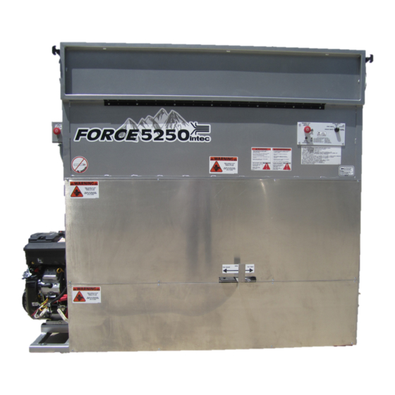
- Page 1 Instruction Manual Insulation blowing machine Original Language – English Intec —9251 Bruin BLVD, Frederick, CO 80504 USA T: 303-833-6644 Web: www.inteccorp.com Email: info@inteccorp.com Rev Date: 2021614...
- Page 2 Engineered for High Productivity and Built-to-Last for High Value Generation. At Intec, we take pride in making your job as easy and profitable as possible. The right system for your needs: Intec strives to provide you with the best combination of portability, functionality, and installation versatility to surpass your desired success.
-
Page 3: Table Of Contents
SAFETY FIRST ....................3 HOW THE SYSTEM WORKS ................. 4 SYSTEM SET-UP: ..............................7 SYSTEM OPERATION: ............................. 9 REPROGRAMMING INTEC’S LONG RANGE TRANSMISSION WIRELESS REMOTE ............10 MAINTENANCE .................... 11 TROUBLESHOOTING ..................13 SPECIFICATIONS ................... 18 ELECTRICAL DIAGRAM ..................19 MAKING A CLAIM FOR DAMAGE OR LOSS ............... -
Page 4: Symbols
Instruction Manual Symbols SYMBOL SYMBOL MEANING Indicates an imminently hazardous situation, which, if not avoided, Danger will result in death or serious injury. Indicates a potentially hazardous situation, which, if not avoided, Warning could result in death or serious injury. Indicates a potentially hazardous situation, which, if not avoided, Caution may result in minor or moderate injury. -
Page 5: How The System Works
Instruction Manual How the System Works OVERVIEW: Cellulose, Fiberglass, or Stone Wool insulation is loaded into the hopper. The agitation system is the first step in processing the insulation while moving towards the airlock column. Once in the column, insulation is processed additionally by the shredder bar. It then moves through the slide gate and into the airlock where the insulation is fed into the airstream created by the blower system. - Page 6 Inlet Hose provides cool clean air from outside the truck / trailer to ensure that your VANGUARD engine is appropriately cooled. The clean air from outside also prevents fibrous particles from being pulled into your engine’s cooling fins. Utilize Intec’s Air Inlet mounting plates to attach the hose coming from machine to fresh air.
- Page 7 Airlock: The airlock transfers the insulation from the agitation system into the airstream without coming into contact with the blowers. Insulation is discharged from the airlock into the hose. Urethane Airlock Seals: Your FORCE 5250 includes Intec’s proprietary urethane airlock seals for long lasting effectiveness. Proper airlock sealing allows for high production rates and high pressures for effective wall fill applications.
-
Page 8: System Set-Up
Instruction Manual The FORCE 5250’s agitation system is built strong to last. Using an advanced design for rugged durability and superior product conditioning. This design allows product to go through multiple stages of conditioning prior to installation. Main Agitator- fluted section allows for maximum mobility and break-up of product. - Page 9 Instruction Manual Once mounted and hardware is tightened, you are ready to fasten the open side of the Fresh Air Inlet to the 8” diameter hose. Upon completion, you will now have fresh, clean air from outside your vehicle used to cool the VANGUARD engine.
-
Page 10: System Operation
Instruction Manual SYSTEM OPERATION: 1. Energize System a. Pull EMERGENCY STOP BUTTONS out (i.e. into the ON position). Choke Ignition Switch with Keys (2) Throttle Oil Quick Drain hose & valve VANGUARD engine shown prior to the installation of the Hose Ring as part of the Fresh Air Inlet Kit. Start VANGUARD engine 1. -
Page 11: Reprogramming Intec's Long Range Transmission Wireless Remote
WIRELESS REMOTE i. Operate system thru Intec’s Long Range Transmission wireless remote. b. WIRED REMOTE i. Operate system thru wireless remote with Intec’s exclusive long lasting urethance jacked controls. ii. Plug wired remote into the REMOTE QUICK DISCONNECT female connector. -
Page 12: Maintenance
Instruction Manual Maintenance Preventative maintenance will provide for many years of trouble-free use. VANGUARD: Please consult the VANGUARD manual for appropriate engine maintenance. A few quick items related to the engine: 1. Initial oil change required after 20 hours of use- made easy with the quick drain hose and valve. a. - Page 13 Airlock Outlet Plate Stainless Steel Inserts SupershredzECO Airlock shown removed from system. The Airlock of your FORCE 5250 is designed for quick removal for maintenance. To watch the complete video on removing and re-installing your Airlock please visit our website at www.inteccorp.com/videos/ T: 303-833-6644 www.inteccorp.com...
-
Page 14: Troubleshooting
Unleaded gasoline. Choke not engaged. Engage Choke. Battery is dead. Charge or replace battery. Advanced Engine issue Contact Intec or local VANGUARD repair facility. Blower(s) does not run. VANGUARD is not running at Move throttle to the full HIGH full throttle. - Page 15 This allows the machine to act as a source to gather the radio frequency waves and enhances reception). Install the optional antenna extender. Contact Intec for details. Transmitter out of range from Move closer to system. Blower and agitator continue to receiver.
-
Page 16: Specifications
Instruction Manual SPECIFICATIONS Weight FORCE 5250 1015 lbs. (461 kg) Hopper size 45 cubic feet Blower – Quantity-1 Positive Displacement Motor VANGUARD 18hp with electric start T: 303-833-6644 www.inteccorp.com Original Language - English... -
Page 17: Electrical Diagram
Instruction Manual Electrical Diagram Force 5250- Standard Wired 2020 T: 303-833-6644 www.inteccorp.com Original Language - English... - Page 18 Instruction Manual Electrical Diagram Force 5250- Standard Wireless 2020 T: 303-833-6644 www.inteccorp.com Original Language - English...
-
Page 19: Making A Claim For Damage Or Loss
Instruction Manual Making a Claim for Damage or Loss Your Intec products were carefully packed and thoroughly inspected before leaving our factory. We understand that damage to or defects with your system may unfortunately occur. Please inspect your shipment carefully upon arrival and save the shipping containers and packaging materials in case of damage. -
Page 20: Warranty
It is expressly understood and agreed that no officer, agent, salesman or employee of the manufacturer Intec (MANUFACTURER) has the authority to obligate the MANUFACTURER by any terms, stipulations, or conditions not herein expressed; that all previous representations and agreements, either verbal or written, referring to the machinery and equipment, which is the subject of this Warranty, are hereby superseded and canceled, and that there are no promises or agreements outside of the Warranty agreement.
Need help?
Do you have a question about the FORCE 5250 and is the answer not in the manual?
Questions and answers