
Related Manuals for dji DROP SYSTEM NAV LIGHT EDITION


Summary of Contents for dji DROP SYSTEM NAV LIGHT EDITION
- Page 1 DROP SYSTEM USER GUIDE (NAV LIGHT EDITION) MAVIC 2 & MAVIC 2 ENTERPRISE Oct 2020 v1.0...
-
Page 2: Table Of Contents
In This Guide… Parts and Components ..................In the Box ......................... Installation and Usage ..................Attaching a Payload ................... Troubleshooting ....................Warranty and Service ..................Terms of Use ...................... -
Page 3: Parts And Components
Parts and Components Your Drop System is designed and assembled entirely by DJI Shop Canada staff in-house. All major components, with the exception of a few parts, are 3D printed and assembled by hand to ensure a sturdy and reliable build. A breakdown of the parts and components are indicated in the illustrations below. -
Page 4: In The Box
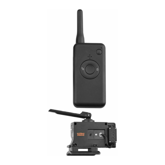
Parts and Components (cont…) 9. Payload Drop Indicator (Lit when pin is in the open position) 10. Power Indicator (Lit when powered on) 11. Power Switch (Down = ON, Up = OFF) In the Box 1x Drop System Assembly 1x 150mAh Li-Po Battery 1x Security Lock 1x Battery USB Charger 1x Electronics Box Cover... -
Page 5: Installation And Usage
To ensure that your Drop System functions correctly, we recommend following the installation and usage guidelines detailed below. Should a part or component not function as explained, please contact DJI Shop Canada for support. Step 1 It is recommended to... - Page 6 Installation and Usage (cont…) Step 3 The clip will snap into place when fully installed. Ensure that the downward vision and IR sensors are not obstructed. The clip must sit between the vision sensor and IR sensor on the belly of the aircraft.
- Page 7 Installation and Usage (cont…) Step 4 Ensure that the clip reaches the top of the battery. Install the clip security lock by inserting into one side of the clip, then stretching to meet the other side of the clip. This will require some force, as the lock is designed to keep tension on the clip, ensuring it cannot detach itself from the aircraft body.
- Page 8 Installation and Usage (cont…) Step 5 Remove the M1 (Front-Right) landing gear extension (if installed) and fold the arm towards the stowed position. Step 6 Slide the navigation light sensor clip upwards towards the motor. It will require slight force to cover the light. Ensure that the wire stays behind the arm and does not get caught.
- Page 9 Installation and Usage (cont…) Step 7 Extend the arm outwards once the navigation light sensor clip has been installed. Ensure that the wire does not get caught while performing this action. Once the arm is extended, there will be tension on the wire, ensuring that it does not droop. Step 8 Reconnect the landing gear extension to the...
- Page 10 Installation and Usage (cont…) Step 9 Remove the electronics box cover by pulling the upper part towards you, then rotating downward to free the lower latch. Step 10 Connect the battery to the battery connector inside the electronics box and tuck the battery inside. Be sure to connect the battery in the proper orientation.
- Page 11 Installation and Usage (cont…) Step 11 Reinstall the electronics box cover after connecting the battery. At this point, ensure that the drop system assembly is installed correctly and does not obstruct the propellers. The drop system is designed with tight tolerances.
- Page 12 The navigation light can be controlled via your RC or directly from the DJI Go 4 or DJI Pilot application on your phone. When the drop system is in the engaged/open position,...
-
Page 13: Attaching A Payload
Attaching a Payload When you’re ready to attach your payload, ensure you have considered the following: The payload does not exceed 1lb/0.45kg. The payload does not contain any dangerous contents. The payload is not too large which may obstruct the downward vision system. - Page 14 Attaching a Payload (cont…) With the payload pin open, insert the included carabiner clip into the cavity underneath the drop system where the payload pin is. Once the clip is inserted, you may release the manual pin release button to close the payload pin. At this point, you may connect your payload to the carabiner clip.
- Page 15 Attaching a Payload (cont…) Once your payload is connected, it must be positioned behind the aircraft to ensure takeoff is unobstructed. Please see the images below for reference. Important things to consider: The line you use to connect your payload must be strong and not frayed.
-
Page 16: Troubleshooting
If the suggested solutions do not work, or you are encountering an issue not listed here, please contact DJI Shop Canada for support or to arrange for a repair/replacement. - Page 17 The manual pin release button does not Check that the unit is powered on. trigger the servo to open. The manual pin release button or switch is Contact DJI Shop Canada to arrange for physically stuck. repair/replacement. Contact DJI Shop Canada to arrange for The red/green LED does not illuminate.
- Page 18 PROBLEM POSSIBLE SOLUTION Check that the charger you are using is functioning correctly. Try moving the charger to a different outlet. The battery is not charging. Replace the charger if it is found not to be functional. Replace the battery if it is found not to be functional.
-
Page 19: Warranty And Service
Warranty and Service Your drop system is covered by a 1 (one) year warranty by DJI Shop Canada (not to be confused with DJI.) Should your unit experience a manufacturing defect or fail unexpectedly during normal use, we will, at our option, repair or replace the unit with new or equivalent to new parts and components in terms of performance and reliability. -
Page 20: Terms Of Use
(1) The drop system is designed and assembled by DJI Shop Canada staff in Toronto, Ontario. Should you experience a product malfunction during the first year of ownership, please contact DJI Shop Canada for service and support.
Need help?
Do you have a question about the DROP SYSTEM NAV LIGHT EDITION and is the answer not in the manual?
Questions and answers