Advertisement
Quick Links
Advertisement

Related Manuals for dji M200 Series


Summary of Contents for dji M200 Series
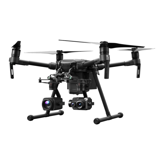
- Page 1 DROP SYSTEM USER GUIDE M200 SERIES Oct 2020 v1.0...
-
Page 2: Table Of Contents
In This Guide… Parts and Components ..................In the Box ......................... Installation and Usage ..................Attaching a Payload .................... Troubleshooting ....................Warranty and Service ..................Terms of Use ...................... -
Page 3: Parts And Components
Parts and Components Your Drop System is designed and assembled entirely by DJI Shop Canada staff in-house. All major components, with the exception of a few parts, are 3D printed and assembled by hand to ensure a sturdy and reliable build. A breakdown of the parts and components are indicated in the illustrations below. -
Page 4: In The Box
Parts and Components (cont…) Rear 8. Navigation Light Cover 9. Light Sensor Wire Routing Clip (Arm) 10. Light Sensor Wire Routing Clip (Bracket) 11. Manual Pin Release Button In the Box 1x Drop System Assembly 1x Li-Po Battery 1x Electronics Bay Cover 1x Battery USB Charger 1x Navigation Light Cover 2x Carabiner Clips... -
Page 5: Installation And Usage
To ensure that your Drop System functions correctly, we recommend following the installation and usage guidelines detailed below. Should a part or component not function as explained, please contact DJI Shop Canada for support. Step 1 Remove the landing gear from your aircraft. - Page 6 Installation and Usage (cont…) Step 3 Remove the landing gear bracket from the airframe of the aircraft. Mind the cable and connector on aircraft equipped with RTK antennas. Repeat steps 1-3 for the opposite side. Step 4 Flip the aircraft either on its side or upside down to attach the drop system bracket.
- Page 7 Installation and Usage (cont…) Step 5 Slide the drop system bracket into place and verify that it is inserted in the correct orientation. The curved cutout on the metal bracket and the electronics bay cover must face the rear of the aircraft, towards the battery compartment. Step 6 Position the landing gear bracket to align the holes...
- Page 8 Installation and Usage (cont…) The replacement screws provided (right) is slightly longer than the stock screws (left) to accommodate for the extra thickness added when attaching the drop system. Step 7 Re-attach both landing gear and stand the aircraft upright.
- Page 9 Installation and Usage (cont…) Step 8 Slide the navigation light cover over the M1 (front-right) motor and press into place until you hear an audible “click” sound. Step 9 Mount the light sensor wire routing clips to the arm. Adjust the routing clips attached to the drop system bracket to ensure adequate tension.
- Page 10 The navigation light can be controlled directly from the DJI Pilot or When the drop system is in the engaged/open position, DJI Go 4 application on your phone, the red LED will illuminate.
-
Page 11: Attaching A Payload
Attaching a Payload When you’re ready to attach your payload, ensure you have considered the following: The payload and camera(s) on the aircraft do not exceed the total maximum payload capacity of your aircraft. The payload does not contain any dangerous contents. The payload is not too large which may obstruct the downward vision system. - Page 12 Attaching a Payload (cont…) With the payload pin open, insert the included carabiner clip into the cavity underneath the drop system where the payload pin is. Once the clip is inserted, you may release the manual pin release button to close the payload pin. At this point, you may connect your payload to the carabiner clip.
- Page 13 Attaching a Payload (cont…) Once your payload is connected, it must be positioned behind the aircraft to ensure takeoff is unobstructed. Please see the images below for reference. Important things to consider: The line you use to connect your payload must be strong and not frayed.
-
Page 14: Troubleshooting
If the suggested solutions do not work, or you are encountering an issue not listed here, please contact DJI Shop Canada for support or to arrange for a repair/replacement. - Page 15 The manual pin release button does not Check that the unit is powered on. trigger the servo to open. The manual pin release button or switch is Contact DJI Shop Canada to arrange for physically stuck. repair/replacement. Contact DJI Shop Canada to arrange for The red/green LED does not illuminate.
- Page 16 PROBLEM POSSIBLE SOLUTION Check that the charger you are using is functioning correctly. Try moving the charger to a different outlet. The battery is not charging. Replace the charger if it is found not to be functional. Replace the battery if it is found not to be functional.
-
Page 17: Warranty And Service
Warranty and Service Your drop system is covered by a 1 (one) year warranty by DJI Shop Canada (not to be confused with DJI.) Should your unit experience a manufacturing defect or fail unexpectedly during normal use, we will, at our option, repair or replace the unit with new or equivalent to new parts and components in terms of performance and reliability. -
Page 18: Terms Of Use
(1) The drop system is designed and assembled by DJI Shop Canada staff in Toronto, Ontario. Should you experience a product malfunction during the first year of ownership, please contact DJI Shop Canada for service and support.
Need help?
Do you have a question about the M200 Series and is the answer not in the manual?
Questions and answers