Table of Contents
Advertisement
Quick Links
Advertisement
Table of Contents
Troubleshooting

Related Manuals for Aerotech UNIDEX 500


Summary of Contents for Aerotech UNIDEX 500
- Page 1 SUBJECT: Unidex 500 Motion Controller and Windows Software Operation & Technical Manual PREPARED BY: Aerotech, Inc. Used with permission 101 Zeta Drive from Aerotech, Inc. Pittsburg, PA 15238-2897 DOCUMENT No: SPIRE-UOL-DOC-001519 ISSUE: Date: February 3, 2003 APPROVED BY: Date:...
- Page 2 500 M OTION INDOWS ONTROLLER AND OFTWARE OPERATION & TECHNICAL MANUAL P/N: EDU150 (V1.3a) AEROTECH, Inc. • 101 Zeta Drive • Pittsburgh, PA. 15238-2897 • USA Phone (412) 963-7470 • Fax (412) 963-7459 Product Service: (412) 967-6440; (412) 967-6870 (Fax) www.aerotechinc.com...
- Page 3 If you should have any questions about the UNIDEX 500 or comments regarding the documentation, please refer to Aerotech online at: http://www.aerotechinc.com. For your convenience, a product registration form is available at our web site. Our web site is continually updated with new product information, free downloadable software and special pricing on selected products.
-
Page 4: Table Of Contents
GETTING STARTED..............2-1 2.1. Introduction ..................2-1 2.2. Unpacking the UNIDEX 500 System ..........2-1 2.3. Inspection of the UNIDEX 500 Control Board ........2-2 CHAPTER 3: SOFTWARE INSTALLATION AND FUNDAMENTALS..3-1 3.1. Introduction ..................3-1 3.2. Minimum Hardware Requirements and Recommended System Configurations .................. - Page 5 Table of Contents UNIDEX 500 and Software 4.3.2.2. Edit Parameters: The Number, Value, and Axis Fields ............. 4-6 4.3.3. System Options..............4-7 4.3.4. The Program Option of the Edit Menu....... 4-14 4.4. The Tools Menu ................4-15 4.4.1. The Diagnostics Option of the Tools Menu ....... 4-15 4.4.2.
- Page 6 UNIDEX 500 and Software Table of Contents 5.3.3. PSO Mailbox Dual_port RAM Base Address ...... 5-8 5.3.4. PSO-HOST and PC Interface Address (U500 ISA - 16 bit MMI software only) ........... 5-9 5.3.5. Plane n Metric System (Y/N) ..........5-10 5.3.6.
- Page 7 Table of Contents UNIDEX 500 and Software 5.7.4. Max Position Error (0-8,388,607) ........5-54 5.7.5. Max Integral Error (0-8,833,607)........5-55 5.7.6. RMS Current Trap (0-100%) ..........5-56 5.7.7. RMS Current Sample Time (1-16,383 ms)......5-58 5.7.8. Clamp Current Output (0-100%) ........5-59 5.7.9.
- Page 8 UNIDEX 500 and Software Table of Contents 5.10.4. Pause Enable in Freerun (Y/N) .......... 5-99 5.10.5. MFO Enable in Freerun (Y/N) ......... 5-100 5.10.6. Calibration Enable (Y/N) ..........5-100 5.10.7. In Position Deadband (Machine Steps) ......5-101 5.10.8. Backlash (Machine Steps) ..........5-102 5.10.9.
- Page 9 Table of Contents UNIDEX 500 and Software CHAPTER 7: PROGRAMMING COMMANDS ..........7-1 7.1. Introduction ..................7-1 7.2. Program Execution Levels..............7-2 7.2.1. Board Level Execution............7-2 7.2.2. C Library Interface ............... 7-2 7.2.3. C Library ASCII Interface............ 7-2 7.3.
- Page 10 UNIDEX 500 and Software Table of Contents 7.8.29. DISABLE................7-58 7.8.30. DS (Display Servo Loop Data) .......... 7-59 7.8.31. DWELL................7-60 7.8.32. DY (Dynamic Gain) ............7-60 7.8.33. EC ..................7-61 7.8.34. ENABLE................7-63 7.8.35. ERROR ................7-64 7.8.36. EXIT .................. 7-65 7.8.37.
- Page 11 9.11. Overriding Scale Factor..............9-16 9.12. COM Functions ................9-19 CHAPTER 10: PROGRAMMING TOOLS ............10-1 10.1. Introduction ..................10-1 10.2. Summary of the UNIDEX 500 Quick Library Functions (32bit) ....................10-2 10.2.1. Overview ................10-2 Aerotech, Inc. Version 1.3...
- Page 12 10.2.4. Quick Library Functions............. 10-4 10.2.5. Arguments and Return Values for the aerq_read_status Function..........10-18 10.2.6. Programming Example............. 10-21 10.3. Summary of the UNIDEX 500 WAPI Functions (32 bit)....10-31 10.3.1. Overview................10-31 10.3.2. Device Driver Information ..........10-31 10.3.3. Registry Information ............10-32 10.3.4.
- Page 13 Option.................. D-7 D.5. Encoder Signal Pinouts..............D-10 D.6. Amplifier Enable Outputs ..............D-11 D.7. Main Connector Pinout of the UNIDEX 500 ........D-12 APPENDIX E: SETTING UP AN AC BRUSHLESS MOTOR WITH THE UNIDEX 500 ..................E-1 E.1. Introduction ..................E-1 E.2.
- Page 14 UNIDEX 500 and Software Table of Contents APPENDIX F: UNIDEX 500 APPLICATIONS ............F-1 F.1. Using the Encoder Position Capture Input - "UINT_N" ....F-1 F.2. Additional UINT features on the U500 PCI card....... F-2 APPENDIX G: U500 CALIBRATION OPTION ............ G-1 G.1.
- Page 15 Table of Contents UNIDEX 500 and Software Aerotech, Inc. Version 1.3...
- Page 16 List of Figures LIST OF FIGURES Figure 1-1. The UNIDEX 500 System Diagram............1-1 Figure 1-2. The UNIDEX 500 Family of Controllers..........1-2 Figure 3-1. Software Menu Available after Completed Installation ......3-3 Figure 3-2. U500 Registry Editor ................3-5 Figure 3-3.
- Page 17 Motor and Encoder Rotation ..............5-64 Figure 5-18. Phase Advance Slope ................5-82 Figure 5-19. U500 Filter Utility................5-87 Figure 6-1. UNIDEX 500 Servo Loop..............6-2 Figure 6-2. Axis Scope Toolbars ................6-2 Figure 6-3. The “Gains” and “Auto Tune” Toolbars..........6-5 Figure 6-4.
- Page 18 Illustration of No Corner Rounding (G24)......... 7-113 Figure 7-11. Illustration of Corner Rounding (G23)..........7-113 Figure 7-12. Optional UNIDEX 500 Joysticks (JBV Model Left, JI Model Right) ....................7-124 Figure 7-13. Plot of Velocity Without Velocity Profiling ........7-136 Figure 7-14.
- Page 19 Electrical Characteristics of the UNIDEX 500 Opto 22 Connections (page 2)................12-17 Figure 12-10. UNIDEX 500 PC Board Jumper Locations ........12-23 Figure 12-11. Typical Connection of the U500 to an Opto-Isolator ......12-27 Figure 12-12. Electrical Characteristics of the UNIDEX 500 Emergency Stop Interface .....................
- Page 20 DR500 Amplifier Chassis ..............1-4 Table 1-3. Available DR500 Amplifier Chassis Options......... 1-4 Table 1-4. Options and Accessories Available for the UNIDEX 500 ..... 1-5 Table 3-1. Minimum Hardware Requirements and Recommendations ....3-1 Table 3-2. Base Address Jumper Settings ............... 3-5 Table 3-3.
- Page 21 Summary of General Purpose Inputs............ 5-67 Table 5-59. Commutation Factors for 4, 6, and 8 Poles .......... 5-68 Table 5-60. Factory Configuration for UNIDEX 500 RDP........5-68 Table 5-61. Feedback Channels, Types, and Additional Hardware......5-70 Table 5-62. Feedback Setup Codes, and the Associated Actions ......5-70 Table 5-63.
- Page 22 UNIDEX 500 and Software List of Tables Table 5-69. Settings for Parameter x41 ..............5-76 Table 5-70. Settings for Parameter x42 ..............5-77 Table 5-71. Sample Commutation Factors for AC Brushless Motors ..... 5-78 Table 5-72. Settings for Parameter x64 ..............5-81 Table 5-73.
- Page 23 UNIDEX 500/Opto 22 Connection Information ........ 12-14 Table 12-11. Main Connector Pinouts for the UNIDEX 500 ISA......12-18 Table 12-12. Analog Input Locations for the UNIDEX 500 ISA ......12-19 Table 12-13. Pinouts for Opto 22 I/O Hall Inputs (P5) ........... 12-20 Table 12-14.
- Page 24 Encoder Signals and Pinouts ............... D-10 Table D-12. Amplifier Enable Output Locations ............ D-11 Table D-13. Main Connector (P1) Pinouts for the UNIDEX 500 ......D-12 Table E-1. Hall State Table..................E-4 Table F-1. Pin Locations of UINT_N Signals ............F-1 Table G-1.
- Page 25 List of Tables UNIDEX 500 andSoftware xxiv Aerotech, Inc. Version 1.3...
- Page 26 This product was tested at Washington Laboratories, LTD in Gaithersburgh, MD on December 12,1995. The report is WLL 2986F. The UNIDEX 500 was tested in a CE–compliant, class B personal computer and it controlled two DC motors, one brushless AC motor and one stepper motor through a DR500 Drive Chassis.
- Page 27 Regulatory Information UNIDEX 500 and Software • Install a Schaffner filter (P/N: FN2080-10-06 or the equivalent) on the DR500 AC power input. • Bond shields of all cables to DR500 chassis. • Add ferrite (P/N: Steward 28B-029-0A0 or the equivalent) to each motor cable at the DR500.
- Page 28 CHAPTER 1: OVERVIEW This chapter contains an overview of the UNIDEX 500 motion controller as well as a sample system diagram. This chapter also contains precautionary notes about installing and using the UNIDEX 500 motion controller. CHAPTER 2:...
- Page 29 Appendix D contains information on test points, jumpers and other technical details for Revision _ PC boards, an earlier production version of the UNIDEX 500. The remainder of the manual pertains to the latest production version of the U500, Revision C.
- Page 30 (1, 2, 3, or 4) may be inserted Capitalized letters within a command indicate the minimum entry for that command (e.g., DIsable) The terms UNIDEX 500 and U500 are used interchangeably throughout this manual • Italic font is used to illustrate syntax and arguments for programming commands •...
- Page 31 A customer survey form is included at the end of this manual for the reader’s comments and suggestions about this manual. Readers are encouraged to critique the manual and offer their feedback by completing the form and either mailing or faxing it to Aerotech. ∇ ∇ ∇...
-
Page 32: Chapter 1: Introduction
1.1. Overview of the UNIDEX 500 System The UNIDEX 500 (or U500) system is a combination of the U500 PC bus-based motion control card, the Windows-based Toolkit or MMI interface software, and any number of optional accessories. The U500 system integrates with amplifiers, positioning stages, and these accessories to form a complete, programmable, customized control system that is suitable for a wide range of motion control applications. -
Page 33: The Unidex 500 Base Model (U500)
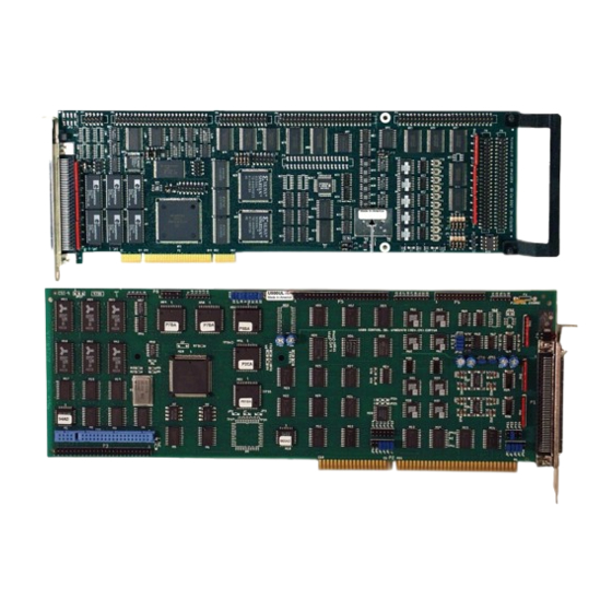
The UNIDEX 500 Family of Controllers 1.2.1. The UNIDEX 500 Base Model (U500) The UNIDEX 500 base model is the basic version of the U500 family. A base model UNIDEX 500 is identified with a small label that reads “UNIDEX 500”. This label is located on the component side of the PC board. -
Page 34: The Unidex 500 Plus Model (U500Plus)
Introduction 1.2.2. The UNIDEX 500 Plus Model (U500PLUS) The UNIDEX 500 Plus model is the version of the U500 family to use if the operator requires basic motion control functions, error mapping, and the ability to program circular-type moves. The Plus model UNIDEX 500 is identified with a small label that reads “UNIDEX 500PLUS”. - Page 35 Introduction UNIDEX 500 and Software Table 1-2 lists the Aerotech motor drivers that can be used when connecting the UNIDEX 500 to the DR500 amplifier drive chassis. Table 1-2. Available Motor Drivers compatible with UNIDEX 500 and DR500 Amplifier Chassis...
-
Page 36: Options And Accessories
1.4. Options and Accessories A variety of options and accessories may be purchased with the UNIDEX 500 to enhance its standard operation. Table 1-4 lists the Aerotech options and accessories that can be used with the UNIDEX 500 Series motion controllers. Brief descriptions of each option follow. -
Page 37: Safety Procedures And Warnings
Introduction UNIDEX 500 and Software 1.5. Safety Procedures and Warnings The following statements apply wherever the Warning or Danger symbol appears within this manual. Failure to observe these precautions could result in serious injury to those performing the procedures and/or damage to the equipment. - Page 38 All electronic equipment is wrapped in antistatic material. Make certain that the antistatic material is not damaged during unpacking. Remove the packing list from the UNIDEX 500 container. Make certain that the items listed on the packing slip are contained within the package. The following items should be found in every UNIDEX 500 system: •...
-
Page 39: Inspection Of The Unidex 500 Control Board
UNIDEX 500 and Software 2.3. Inspection of the UNIDEX 500 Control Board Before touching the UNIDEX 500 control board, be sure to observe the electrostatic discharge precautions listed below. The U500 board is sensitive to static electricity. To greatly reduce the possibility of board damage due to electrostatic discharge, adhere to the following precautions. -
Page 40: Chapter 3: Software Installation And Fundamentals
• Minimum Hardware Requirements and Recommended System Configurations ..............3-1 • Standard Installation Using Windows NT 4.0 or 95.... 3-2 • Installing the UNIDEX 500 PC Board ........ 3-3 • Software Startup ..............3-4 • Software Configuration Considerations....... 3-9 • Special Startup Considerations.......... 3-11 3.1. -
Page 41: Standard Installation Using Windows Nt 4.0 Or 95
Software Installation and Fundamentals UNIDEX 500 and Software 3.3. Standard Installation Using Windows NT 4.0 or 95 To install the software, the operator must follow the steps listed below. Start Microsoft Windows NT 4.0, 95, or 98. Place the installation CD in your CD-ROM drive. -
Page 42: Installing The Unidex 500 Pc Board
3.4. Installing the UNIDEX 500 PC Board The UNIDEX 500 control board is a full-sized AT/PCI card that is installed into any of the PC’s unused expansion slots. The UNIDEX 500 PC control board may not fit in some smaller models of PCs. -
Page 43: Software Startup
0x300-0x30F. The UNIDEX 500 interface software is also set to this default address. If the UNIDEX 500 control board does not initialize properly or exhibits sporadic operation, there may be another board in the system computer that is set to the same address. -
Page 44: Configuring The Software To Match The Hardware
UNIDEX 500 and Software Software Installation and Fundamentals Each UNIDEX 500 control board must have a distinct address in the same PC. Table 3-2. Base Address Jumper Settings PC I/O Base Settings Address 5 6 7 200 - 20F 5 6 7... -
Page 45: Configuration Of The Software For The Isa Board
Play” standard. Windows NT will automatically configure the software to match the U500 PCI board. If you are using Win 95 or Win 98, after installing the UNIDEX 500 PCI card, the operating system will display a message “New Hardware Found”. Take the... -
Page 46: Initializing The U500 Board
PCI and ISA versions of the UNIDEX 500 Controller cannot be mixed. 3.5.5. Initializing the U500 Board Once the device driver is properly configured, start the UNIDEX 500 MMI or Toolkit software. If a message stating “Could not open board or driver not running”occurs, please refer back to the “Configuring the Software”... -
Page 47: Figure 3-5. The Axis Position Window
The parameter file should default to U500.PRM. If your system has been configured at Aerotech, the parameter file will be the customer order number, i.e. 101234.PRM. If you are using an ISA card, the correct firmware file to be used is “U500C.JWP”. If you are using a PCI card, the correct firmware file is “U500PCI.JWP”. -
Page 48: Software Configuration Considerations
3.6. Software Configuration Considerations Prior to any motion control or programming, the UNIDEX 500 software must be properly configured. Although the software has many parameters, only a small group must be configured to get started. This section highlights only those parameters that are most important in order to form a basic operating foundation for the control system. - Page 49 Software Installation and Fundamentals UNIDEX 500 and Software Table 3-3. Key UNIDEX 500 Configuration Parameters Parameter Group Parameter Description Default Number Value(s) 1. Advanced Motion Axis 1 gantry (y/none), slave (2,3,4) None Axis 2 gantry (y/none), slave (1,3,4) None Axis 3 gantry (y/none), slave (1,2,4)
-
Page 50: Special Startup Considerations
(see Figure 3-6). Parameters are organized into logical groups that are displayed on “tabs” in the Edit Parameters popup window. The General and Axis tabs collectively contain all of the UNIDEX 500 parameters. The other tabs (numbers 0-8) contain subsets of these parameters organized into functional groups (e.g., basic motion, faults, position tracking, etc.). -
Page 51: Figure 3-7. The Diagnostics Popup Window
Diagnostic window (Figure 3-8) is accessible from the File Menu of the Diagnostic window shown above. The UNIDEX 500 software also contains a tracking display window that shows position data in real time. The position is displayed in programmable units that the operator may define (e.g., mm, in, etc.). -
Page 52: Figure 3-8. The Diagnostics 2 Popup Window
UNIDEX 500 and Software Software Installation and Fundamentals Figure 3-8. The Diagnostics 2 Popup Window Make certain that all system traps and faults are enabled prior to initiating any axis movement. For more information, refer to the faults, traps, and mask parameters in Chapter 5. -
Page 53: Figure 3-9. The Axis Position Display
Software Installation and Fundamentals UNIDEX 500 and Software Figure 3-9. The Axis Position Display (Choose Windows Axis Display Show) Figure 3-10 is a flowchart that summarizes the installation process from installing the software through preliminary servo loop setup. Install the U500... -
Page 54: Feedback Verification
If the feedback does not perform as noted above, refer to the introduction to Motor and Feedback Configuration (in Chapter 6) and Chapter 13 (Troubleshooting). Make certain that the UNIDEX 500 is appropriately configured for the type of motor being driven. -
Page 55: Table 3-4. Servo Loop Tuning Parameters
Software Installation and Fundamentals UNIDEX 500 and Software In the UNIDEX 500 system, there are five tuning parameters associated with each axis. Each set of servo tuning parameters must be properly configured before the associated axis can be enabled. The five servo loop tuning parameters are listed in Table 3-4. -
Page 56: Chapter 4: The Software Interface
Introduction This chapter explains the options that are available through the MMI software interfaces for the UNIDEX 500 motion controller. The U500 comes with Toolkit software. Uurà U‚‚yxv‡Ã †‚s‡h…rà v†Ã vpyˆqrq Additional functionality is provided by the MMI software interface (if purchased). -
Page 57: The File Menu
The Software Interface UNIDEX 500 and Software 4.2. The File Menu The File menu is a pull-down menu of the U500 software that contains the commands listed in Table 4-1. The underscored letters in the table indicate “short cut keys.” Once the pull-down menu has been activated, hitting an underscored key activates the command. -
Page 58: The Project
RESET button or the Functions menu) for the new parameter file to take effect. 4.2.3. The Firmware... Option of the File Menu The Firmware... option of the File menu is used to load the UNIDEX 500 firmware file into memory. When this option is selected, the operator selects the firmware file name (with extension .JWP). -
Page 59: The Reset Option Of The File Menu
4.2.5. The Reset Option of the File Menu The Reset option of the File menu is used to initialize the UNIDEX 500 system. Selecting this option has the same effect as selecting the F9 Reset soft key at the bottom of the main screen, selecting the Reset option from the Functions menu, or pressing the F9 function key on the keyboard. -
Page 60: The Parameters
The Parameters... option of the Edit menu is used to edit parameter values for the UNIDEX 500 system. When this option is selected, the edit parameters screen is displayed. This screen contains 11 parameter tabs (that categorize parameters by their function). -
Page 61: Edit Parameters: The File Submenu
The Software Interface UNIDEX 500 and Software Figure 4-3. The Edit Parameters Screen 4.3.2.1. Edit Parameters: The File Submenu The File submenu of the “Edit Parameters” screen contains options to open an existing parameter (.PRM) file, save changes to the current .PRM file, save to a new .PRM file name, and print parameters. -
Page 62: System Options
The System Options screen opens at the “Defaults” index tab. The four text boxes labeled “Board...” are available to select the default project (.PRJ) for each UNIDEX 500 board in the system. The “Program:” text box defines a default program (.PRG) for the system. - Page 63 The “Global Subroutine” text box is available to specify a file that contains subroutines that can be accessed from any UNIDEX 500 program that is being executed. Refer to the “Programming commands” section of this manual for the proper syntax of subroutines.
- Page 64 UNIDEX 500 and Software The Software Interface Refer to following example global subroutines: :_ABORT ; ABORT subroutine abort me di "Motion Aborted" return :_FAULTACK FAULT ACKNOWLEDGE SUBROUTINE – abort faultack me di "Fault Cleared" return :_HOME1 ; HOME AXIS 1 SUBROUTINE –...
- Page 65 The Software Interface UNIDEX 500 and Software :_DISABLE1 ; DISABLE AXIS 1 SUBROUTINE – disable x return :_DISABLE2 ; DISABLE AXIS 2 SUBROUTINE – me di "Disabled Axis 2" di y return :_DISABLE3 ; DISABLE AXIS 1 SUBROUTINE – return ;...
-
Page 66: Figure 4-5. Abort Options Tab Of The Mmi System Options Screen
The LZR Setup options tab is shown in Figure 4-6. The LZR Setup tab is used if an LZR2100 laser interferometer card and/or a LZR1100 Environmental Compensation Unit accompany the UNIDEX 500 card. This tab sets the calibration file for the LZR1100 and/or the setup file for LZR2100. -
Page 67: Figure 4-6. Lzr Setup Tab Of The Mmi System Options Screen
The Software Interface UNIDEX 500 and Software The LZR Options are as follows: • “Do Not Use LZR Functions” This option disables LZR functionality. • “Use the LZR2100 with the LZR1100” This option allows use of the PC-based LZR2100 board •... -
Page 68: Figure 4-7. Fpga Setup Tab Of The Mmi System Options Screen
UNIDEX 500 and Software The Software Interface Encoder 5-8 allows the U500 PCI to accept encoder feedback on channels 5- 8 for dual loop servo control Single PSO the U500 PCI will track the position of a single axis encoder channel. -
Page 69: The Program Option Of The Edit Menu
4.3.4. The Program Option of the Edit Menu The Program option of the Edit menu is used to view/edit/create a motion control program for the UNIDEX 500 system. The program editor appears as a window within the main screen. When the program editor is displayed, the options in the menu bar change. During program edits, the menu bar displays the File and Edit menus. -
Page 70: The Tools Menu
UNIDEX 500 and Software The Software Interface 4.4. The Tools Menu The Tools menu is a pull-down menu that contains the commands listed in Table 4-5. Table 4-5. Tools Menu Commands Command Description Diagnostics Display diagnostics window Demo Enable demo mode for software “operation” without a U500 board Axis Tuning... - Page 71 The Software Interface UNIDEX 500 and Software Hitting the <ENTER> key also closes the diagnostics window. When using the U500 PCI, the File menu also contains the Diagnostics 2 option that is used to provide diagnostic information for axes 5-8, the A/D Inputs 5- 8 and the additional 24 I/O lines that are available.
-
Page 72: Table 4-6. Software Status Diagnostics
UNIDEX 500 and Software The Software Interface Table 4-6. Software Status Diagnostics (continued) Field Description Soft CCW Limit Indicates if the CCW software limit (machine steps) (x22) has been exceeded (* = x22 has been exceeded) Feedback Trap Indicates that the feedback signal from the feedback device has... - Page 73 The Software Interface UNIDEX 500 and Software Table 4-8. Hardware Status Diagnostics Field Description CW Limit Indicates the current hardware input level of the CW limit input (H = “high” signal, L = “low” signal) CCW Limit Indicates the current hardware input level of the CCW limit input (H = “high”...
-
Page 74: The Demo Option Of The Tools Menu
The Demo option of the Tools menu is used as a diagnostic tool to allow access to virtually all of the software screens and menus without having to install a UNIDEX 500 board in the PC. When this option is selected, a check mark appears next to “Demo” in the menu. -
Page 75: The Axis Tuning
The Software Interface UNIDEX 500 and Software 4.4.3. The Axis Tuning... Option of the Tools Menu The Axis Tuning... option of the Tools menu is used to display Axis Scope, a display and loop tuning utility. When this option is selected, the Axis Scope screen is displayed. The Axis Scope screen contains a menu bar with loop tuning and display options. -
Page 76: Axis Scope: The Plot Submenu
UNIDEX 500 and Software The Software Interface 4.4.3.2. Axis Scope: The Plot Submenu The Plot submenu of the Axis Scope screen contains options that allow the operator to specify plot options and which functions to plot. Submenu options are listed in Table 4-11. -
Page 77: Axis Scope: The Trigger Submenu
The Software Interface UNIDEX 500 and Software 4.4.3.3. Axis Scope: The Trigger Submenu The Trigger submenu of the Axis Scope screen contains options that allow the operator to specify a data collection method (Collect One Set of Data or Collect Data Continuously), motion options (Single Step Motion, Auto Step Motion, Forward Motion, Reverse Motion), and control options (Stop, Abort, and Sample Rate). -
Page 78: Axis Scope: The Collect Submenu
UNIDEX 500 and Software The Software Interface Figure 4-10. Reverse Motion... Popup Window When the Sample Rate option is selected, the software displays the Scope Sample Timebase popup window. From this popup the operator enters the frequency at which samples are to be taken. This value is given in milliseconds (ms) and defaults to a value of 1 ms. -
Page 79: Axis Scope: The Display Submenu
This submenu supports axes 1, 2, 3, and 4. When selected, the axis name has a check mark to its left. The Axis submenu is illustrated in Figure 4-14. (The UNIDEX 500 Base model can only collect data for a single axis. The Plus and Ultra can collect all four axes of data). -
Page 80: Axis Scope: The Units Submenu
UNIDEX 500 and Software The Software Interface Figure 4-14. Axis Submenu of the Axis Scope Screen 4.4.3.7. Axis Scope: The Units Submenu The Units submenu of the Axis Scope screen specifies the distance and time measurement units for the plot display. Distance units can be displayed in any one of the following units: Machine Steps, millimeters (mm), microns (mm / 1000), Inches, and thousandths of inches (Inches / 1000). -
Page 81: Figure 4-16. Tools Submenu Of The Axis Scope Screen
The Software Interface UNIDEX 500 and Software Figure 4-16. Tools Submenu of the Axis Scope Screen The Cursors option is used to display/hide the Cursors tool bar. This tool bar contains features that assist the operator in determining time differences between points on the plot as well as frequency information. - Page 82 UNIDEX 500 and Software The Software Interface Figure 4-18. Status Tool Bar of the Axis Scope Screen The Control option is used to display/hide the Control tool bar. This tool bar contains features such as an MDI command box, program step buttons, and control buttons. The Control tool bar is illustrated in Figure 4-19.
-
Page 83: Figure 4-20. Gains Toolbar Of The Axis Scope Screen
The Software Interface UNIDEX 500 and Software Figure 4-20. Gains Toolbar of the Axis Scope Screen The Autotune option is used to display/hide the autotune tool bar. See Section 6-7 for a description on how to use autotuning. The Frequency Response is used to display/hide the frequency response toolbar. The Frequency Response toolbar is shown in Figure 4-21. -
Page 84: Figure 4-22. Fft Toolbar Of The Axis Scope Screen
UNIDEX 500 and Software The Software Interface The FFT option in the Axis scope window is used to display/hide the FFT window. This window can be used to apply the Fourier Transform to a set of data collected in the Axis Scope window. - Page 85 The Software Interface UNIDEX 500 and Software Table 4-14. Plot Submenu Options of the Axis Scope Screen (continued) Command Description Position Feedback Computes the FFT of the position feedback of the selected axis Position Computes the FFT of the comanded position to the selected axis...
-
Page 86: The Joystick Digitizing Option Of The Tools Menu
UNIDEX 500 and Software The Software Interface (Re(Y + Im(y The Nyquist frequency of the data is determined by the time-base used to collect the data. For example, the sample rate in the Axis Scope window was 1ms (1kHz), then the Nyquist frequency is 500 Hz. -
Page 87: Figure 4-24. Joystick Digitizing Window
The Software Interface UNIDEX 500 and Software This move will be either an incremental or absolute distance depending on the programming mode being used. If “CW” or “CCW” was selected, move the axes to one location along the arc and hit joystick button C. -
Page 88: The "Diagnostics 2" Option Of The Tools Menu
UNIDEX 500 and Software The Software Interface 4.4.5. The “Diagnostics 2” Option of the Tools Menu (U500 PCI Only) When using the U500 PCI, the File menu also contains the Diagnostics 2 option (Figure 4-25). This is used to provide diagnostic information for the additional 24 I/O lines, A/D inputs 5 –... -
Page 89: The Variable Watch Option Of The Tools Menu
The Software Interface UNIDEX 500 and Software limit, H=high limit), the encoder fault status (Y=yes, N=no) for SIN and COS signals for each of the four encoders, etc…). The values of analog-to-digital inputs 5-8 are also shown in this window. -
Page 90: The Windows Menu
UNIDEX 500 and Software The Software Interface 4.5. The Windows Menu The Windows menu is a pull-down menu of the U500 software that contains the commands listed in Table 4-15. Figure 4-27 shows the main software screen with all of the available windows enabled. -
Page 91: The F2 Abort Button
The Software Interface UNIDEX 500 and Software Figure 4-27. Software Screen with All Windows Visible 4.5.1.1. The F2 Abort Button The F2 Abort button is used to terminate the execution of the program or any motion that is currently running. The U500 command buffer is cleared. After program execution has been stopped (aborted), the program can be restarted using the Restart button (on the program display window [after selecting F4 Load]) and then the Cycle button. -
Page 92: Figure 4-28. Program Control Window After F4 Load Of Untitled.prg
UNIDEX 500 and Software The Software Interface This window (shown in Figure 4-28) displays the program code as well as six program control buttons. If the F5 Jog button is selected, the Program Display window is closed and the Jog window is displayed. -
Page 93: The F5 Jog Button
The Software Interface UNIDEX 500 and Software line is executed) or Auto (the program runs completely until it is stopped, aborted or an error occurs). The Cycle button is used to start execution of the .PRG file that is currently loaded into memory. -
Page 94: Password Protection
UNIDEX 500 and Software The Software Interface Figure 4-29. The F5 Jog Window 4.5.1.5. Password Protection The MMI software provides the user the capability to password protect the levels of availability to other users. For example, one user may be allowed access to the Jog window upon system start up, while another user and his password is not. -
Page 95: Figure 4-30. System Password Prompt Window
The Software Interface UNIDEX 500 and Software Figure 4-30. System Password Prompt Window Figure 4-31. System Password Window Aerotech, Inc. 4-40 Version 1.3... - Page 96 Parameters, and Configuration under both File and Edit menus. Also Firmware under the File menu and System Options under the Edit menu. These options are used to setup the UNIDEX 500 card. Desktop Config The options affected are the menu items: Functions, Status, Mdi, and MFO under the Windows menu.
-
Page 97: The F7 Diag Button
4.5.1.8. The F9 Reset Button The F9 Reset button is used to initialize the UNIDEX 500 system. Selecting this option has the same effect as selecting the Reset option of the File menu, selecting the Reset option from the Functions menu, or pressing the F9 function key on the keyboard. -
Page 98: The Status Option Of The Windows Menu
UNIDEX 500 and Software The Software Interface 4.5.2. The Status Option of the Windows Menu The status bar is a window that is displayed at the bottom of the main software screen (above the function buttons if they are displayed). The status bar has 17 cells that contain status information about the system. -
Page 99: Table 4-17. Cell Descriptions Of The Status Bar
The Software Interface UNIDEX 500 and Software Table 4-17. Cell Descriptions of the Status Bar Status Cell # Description/Display Double Click on Cell Causes... Current project file name (or blank) Open new project popup window Current programming mode Toggles between incremental and absolute... -
Page 100: The Jog Option Of The Windows Menu
UNIDEX 500 and Software The Software Interface 4.5.3. The Jog Option of the Windows Menu See Section 4.5.1.4. for more information. 4.5.4. The Gain Adjust Option of the Windows Menu The Gain Adjust option of the Windows menu is used to display the Gain Adjust popup. -
Page 101: The Mfo Option Of The Windows Menu
The Software Interface UNIDEX 500 and Software 4.5.6. The MFO Option of the Windows Menu MFO stands for Manual Feedrate Override. The MFO option of the Windows menu is used to display the MFO Adjust popup. From this popup, the operator can manually change the current feedrate. -
Page 102: Table 4-18. Axis Display Options
UNIDEX 500 and Software The Software Interface Figure 4-37. The Axis Display Menu with Options Figure 4-38. The Axis Display Window Showing Six Options Table 4-18. Axis Display Options Option Description Enable Displays enable buttons (X, Y, Z and U) for each of the axes... -
Page 103: The Functions Menu
The Software Interface UNIDEX 500 and Software 4.6. The Functions Menu The Functions menu of the main software screen contains the eight functions from the Windows / Functions option. These options correspond to the functions menu across the bottom of the software screen (when enabled) and the F2 through F9 function keys on the keyboard. -
Page 104: The Help Menu
UNIDEX 500 and Software The Software Interface 4.7. The Help Menu The Help menu (Figure 4-40) has three options: Contents, Search for Help On…, and About…. The Contents and Search for Help On reference the U500 On-Line Help File: u500nw.hlp installed in the \u500\mmi\help subdirectory. The On-Line help file contains the help on all programming commands and information on the software interface. -
Page 105: Figure 4-41. The About Popup Window
The Software Interface UNIDEX 500 and Software Figure 4-41. The About Popup Window ∇ ∇ ∇ Aerotech, Inc. 4-50 Version 1.3... -
Page 106: Chapter 5: Parameters
• The Axis Tab ..............5-112 5.1. Introduction SAMPLE This chapter describes all of the parameters of the UNIDEX 500 system. Parameters are 0. Position Tracking divided into 11 sections based on the tabs in the Edit Parameters window. Additional 1. Advanced Motion sections are included to explain topics that are closely related to the parameters. -
Page 107: The Menu Bar Of The Edit Parameters Window
• Axis Each of the numbered tabs contains a subset of the list of UNIDEX 500 parameters. All of the UNIDEX 500 parameters can be accessed through tabs 0 through 8 or through the General and Axis tabs. The General and Axis tabs provide a grouping that is more generalized than the nine specialized tabs. -
Page 108: The Parameter Value Field
UNIDEX 500 and Software Parameters Parameter numbers provide an additional way to differentiate parameters. Experienced operators may find parameter numbers easier to manipulate than their text counterparts. Refer to Figure 5-1. The parameter number field may also be used to locate a particular parameter based on its number. -
Page 109: Axis Number Radio Buttons
Parameters UNIDEX 500 and Software 5.2.6. Axis Number Radio Buttons Axis number radio buttons are provided in the lower right corner of the Edit Parameters window. These buttons provide a method for quickly switching between axis parameters. Only one axis radio button can be selected at a time. For general parameters, the axis radio buttons are inactive (current radio button is selected). -
Page 110: The Position Tracking Tab
The position tracking and display parameters are used to define the scaling and resolution 2. Basic Motions of the UNIDEX 500 system in either the Metric (the default) or English measurement systems. Configuration parameters for the optional PC-PSO board are also included. -
Page 111: Keep Axis Position After Reset (Y/N)
Keep Axis Position after Reset (Y/N) 0. Position Tracking Parameter 001 configures the UNIDEX 500 to either clear (that is, set to 0) all absolute, 1. Advanced Motion relative and machine positions following a PC reset (no) or to retain the current axis 2. -
Page 112: Axis N Rollover Machine Steps For Axes 1-4
This allows the 5. Motor Feedback axis position to be read in units such as degrees. The sizes of the UNIDEX 500’s absolute, 6. Servo Loop relative and machine position registers are 47 bits plus one sign bit. This gives the position registers a range of 0 to 2 -1. -
Page 113: Pso Mailbox Dual_Port Ram Base Address
PSO Mailbox Dual_port RAM Base Address 0. Position Tracking The UNIDEX 500 has several optional accessories that can be used to augment the 1. Advanced Motion operation of the system. One such option is the PC-PSO board (refer to Chapter 1 for 2. -
Page 114: Pso-Host And Pc Interface Address (U500 Isa - 16 Bit Mmi Software Only)
0x360 PC-PSO host base address is 0x360 If you are using the 16 bit UNIDEX 500 software and parameter 016 (PSO Host and PC Interface Base Address) is set to 0 (the software default which indicates that a PC-PSO board is not used), the PC-PSO will not initialize. This parameter must be set to a unique address for proper operation and must agree with the hardware address setting specified by jumpers JP2-JP7 on the PC-PSO board. -
Page 115: Plane N Metric System (Y/N)
Parameters UNIDEX 500 and Software 0. Position Tracking 1. Advanced Motion 5.3.5. Plane n Metric System (Y/N) 2. Basic Motions These parameters specify the default use of the Metric or English measurement systems 3. Homing/Limits when programming the conversion factor for contour planes 1-4, respectively. The 4. -
Page 116: Metric Mode Number Of Decimal Digits (1-8)
UNIDEX 500 and Software Parameters 0. Position Tracking 5.3.6. Metric Mode Number of Decimal Digits (1-8) 1. Advanced Motion These parameters set the number of zeros that are added after the decimal place in Metric 2. Basic Motions mode displays. They are used in conjunction with parameter x00 (Metric conversion 3. -
Page 117: English Mode Number Of Decimal Digits (1-8)
Parameters UNIDEX 500 and Software 0. Position Tracking 1. Advanced Motion 5.3.7. English Mode Number of Decimal Digits (1-8) 2. Basic Motions These parameters set the number of zeros that are added after the decimal place in 3. Homing/Limits English mode displays. They are used in conjunction with parameter x01 (English 4. -
Page 118: The Advanced Motion Tab
User interrupt setup code Abort on input high (0, 1-16) After changing one or more parameter values, always reinitialize the UNIDEX 500 board to make the changes take effect. This is done using the F9 RESET button located at the bottom of the main software window. -
Page 119: Overview Of Planes
5.4.1. Overview of Planes 0. Position Tracking The UNIDEX 500 system can control up to four axes of motion as well as miscellaneous 1. Advanced Motion inputs and outputs. Typically, these inputs, outputs, and/or axes are controlled from a 2. Basic Motions program that is written for the particular application. - Page 120 The UNIDEX 500 executes the first (and then subsequent) lines in each plane in a round-robin fashion called multitasking. The multitasking is performed so quickly that the planes appear to be executing simultaneously.
- Page 121 (in plane 2). This is followed by a linear X-axis move of 10,000 units (in plane 1). By using planes and multitasking, the UNIDEX 500 is able to carry out the request in plane 1 before the request in plane 2 is finished (i.e., before the Y-axis completes its 50,000-unit linear move).
-
Page 122: Number Of Contour Planes (1, 2, 4)
4. Traps 5. Motor Feedback The program buffer of the UNIDEX 500 is fixed at 8 Kbytes regardless of the number of 6. Servo Loop contour planes selected. One, two, or four planes may be used for maximum flexibility 7. - Page 123 Parameters UNIDEX 500 and Software It is suggested that the number of contour planes set by this parameter be as small as possible for the application. Doing this will provide the maximum buffer size and the fastest processing time. Following configuration of this parameter, the system must be reinitialized so that the new number of planes is recognized.
-
Page 124: Axis N Map To Plane {1-4} As {X, Y, Z, U
Axis one is always assigned to amplifier/drive channel one, axis two to amplifier/ drive channel two, etc. An axis must not be assigned to more than one contour plane. If the UNIDEX 500 system is inadvertently configured this way, a feedback error is generated. -
Page 125: Axis N Gantry {Y/None}, Slave {1, 2, 3, 4
Parameters UNIDEX 500 and Software 5.4.4. Axis n Gantry {Y/None}, Slave {1, 2, 3, 4} 0. Position Tracking When performing contour-type moves, it may be desirable to pair axes in a master/slave 1. Advanced Motion relationship. In such configurations, motions commanded to the master axis are 2. - Page 126 UNIDEX 500 and Software Parameters By default, gantry axes are linked together at all times except for home cycles. The home cycles are done independently except during the marker search. Each axis does an independent search for its marker (for encoders) or null (for resolvers). When one axis finds its marker, it will wait for the other to complete its marker search.
-
Page 127: Figure 5-7. Using Home Offset Parameter To Keep Gantry Aligned After
Parameters UNIDEX 500 and Software Motor Clockwise Direction Master A xis Motor Counterclockwise Direction Encoder or Resolver Master marker location or resolver null (linearized) Motor Master Home Offset (x06= Master axis Home switch Not Shown to Scale Slave A xis... -
Page 128: Plane N Indexing Segment Time (1-20 Ms)
5.4.5. Plane n Indexing Segment Time (1-20 ms) 2. Basic Motions During trajectory generation, the UNIDEX 500 divides the motion into segments. This 3. Homing/Limits parameter represents the motion time for each segment (in milliseconds [ms]). The default 4. Traps setting of 10 ms is sufficient for most applications. -
Page 129: Linear Type Ac/De (Y/N)
0. Position Tracking 5.4.6. Linear Type Ac/De (Y/N) 1. Advanced Motion The UNIDEX 500 supports two types of acceleration/deceleration (ac/de) ramping 2. Basic Motions trajectories: linear and sine. Each contour plane must be delineated as either linear or sine 3. Homing/Limits 4. -
Page 130: Clamp Feedrate (Program Steps/Ms)
0.0004 to 32,767 program steps/ms (default = 256.0) If a contour feedrate (programmed or derived after MFO adjustment) is larger than the setting of this parameter, then the UNIDEX 500 will automatically clamp it to the appropriate Clamp feedrate value. -
Page 131: Corner Rounding Non-Ramp Time (1-32,000 Ms)
Parameters UNIDEX 500 and Software 0. Position Tracking 5.4.8. Corner Rounding Non-Ramp Time (1-32,000 ms) 1. Advanced Motion Corner rounding can be used to remove sharp edges on corners from a profile. It does this 2. Basic Motions by blending the deceleration of the current move with the acceleration of the next move. - Page 132 UNIDEX 500 and Software Parameters When corner rounding is not used (e.g., G24 or ROUNDING OFF programming command), each contour path decelerates to its target position before the next block of motion begins. Refer to Figure 5-11. Velocity = acceleration...
-
Page 133: Contouring Mode
Parameters UNIDEX 500 and Software 5.4.9. Contouring Mode 0. Position Tracking These parameters select the contouring mode. The default is 0, which uses the normal 1. Advanced Motion contouring mode, and 1 selects the alternate contour mode. This parameter is used to turn 2. -
Page 134: A/D Channel N Joystick Deadband
UNIDEX 500 and Software Parameters 5.4.10. A/D Channel n Joystick Deadband 0. Position Tracking 1. Advanced Motion These parameters define the deadbands associated with the center position of the joystick. 2. Basic Motions There is no resulting motion when the joystick is within this band. The parameter value is 3. -
Page 135: A/D Channel N Joystick Center Position
5.4.12. Safe Zone Output Bit (0-8) Parameter 098 specifies which UNIDEX 500 output to turn on (low) when all axes are in their specified safe zones. See parameters x75 and x76 under Homing and Limits for an explanation of safe zone. -
Page 136: Option Board Setup Code
UNIDEX 500 and Software Parameters 0. Position Tracking 5.4.13. Option Board Setup Code 1. Advanced Motion 2. Basic Motions Parameter 099 indicates which option board is being used. The option board is determined by the status of the first two bits of parameter 099. Entering an appropriate 3. -
Page 137: User Interrupt Setup Code
Parameters UNIDEX 500 and Software 5.4.14. User Interrupt Setup Code 0. Position Tracking Parameter 500 sets the usage of the user interrupt input. The usage is determined by the 1. Advanced Motion status of the first two bits of parameter 500. Entering an appropriate decimal value for the 2. -
Page 138: The Basic Motion Tab
5.5. The Basic Motion Tab 0. Position Tracking The basic motion parameters are used to configure the UNIDEX 500 for basic motion. Parameters on this tab define ramping times and feedrates for axes and contour planes. 1. Advanced Motion There are 25 parameters in the basic motion parameter group. These parameters are 2. -
Page 139: Mfo, 0 No Mfo-Pot, 1-255 Pot Offset
Parameters UNIDEX 500 and Software 0. Position Tracking 5.5.1. MFO, 0 No MFO-pot, 1-255 Pot Offset 1. Advanced Motion 2. Basic Motions This parameter is used to enable or disable an optional manual feed override (MFO) potentiometer (pot). The MFO pot, if used, is attached to the miscellaneous I/O connector 3. -
Page 140: Plane N Contour Ramping Time (Ms)
UNIDEX 500 and Software Parameters 0. Position Tracking 5.5.2. Plane n Contour Ramping Time (ms) 1. Advanced Motion 2. Basic Motions The acceleration and deceleration time of linear and circular motion is set using parameters 019, 037, 055, and 073 (refer to Figure 5-13). These parameters also specify 3. -
Page 141: Contour Feedrate (Program Steps/Ms) For Plane N
Parameters UNIDEX 500 and Software 0. Position Tracking 5.5.3. Contour Feedrate (Program Steps/ms) for Plane n 1. Advanced Motion These parameters specify a default feedrate (in program steps/ms) to be used by axes in 2. Basic Motions each contour plane if a feedrate is not explicitly stated (in the program) for that plane. -
Page 142: The Homing And Limits Tab
The Homing and Limits Tab 0. Position Tracking The homing and limits parameters are used to configure the UNIDEX 500’s home cycle 1. Advanced Motion and the accompanying limit switches. The home cycle is the process in which an axis is 2. -
Page 143: The Home Cycle
The home cycle is used to move specified axes to a hardware referenced position. Two 4. Traps distinct types of home cycles are used by the UNIDEX 500: the power-on home cycle and 5. Motor Feedback the runtime home cycle. There are individual axis feedrates associated with each of these 6. -
Page 144: Figure 5-14. Home Cycle
UNIDEX 500 and Software Parameters Direction (x02) Power-on Home Feedrate (x04) / Home Feedrate (x05) Home Limit Switch Home Current Home Feedrate Position Feedrate (x05) Max Accel (x05) (x16) Max Accel Max Decel Max Decel (x16) (x16) (x16) Home Limit... -
Page 145: Home Direction Is Ccw (Y/N)
Home Direction is CCW (Y/N) 1. Advanced Motion Each axis of the UNIDEX 500 needs to be configured for the direction that the axis motor 2. Basic Motions will turn when going to the home position (refer to Figure 5-14 on page 5-39). This 3. -
Page 146: Home Switch Normally Open (Y/N)
Home limit switch is normally closed Yes (Y) Home limit switch is normally open (default) No (N) Home limit switch is normally closed The limit inputs are pulled to logic high on the UNIDEX 500 control board. Aerotech, Inc. Version 1.3 5-41... -
Page 147: Power-On Home Feedrate (Machine Steps/Ms)
Parameters UNIDEX 500 and Software 0. Position Tracking 5.6.4. Power-on Home Feedrate (Machine Steps/ms) 1. Advanced Motion Following power-up, the first commanded home cycle will be a power-on home cycle. 2. Basic Motions The axis will move at the feedrate set by parameter x04 (the Power-on home feedrate 3. -
Page 148: Normal Home Feedrate (Machine Steps/Ms)
UNIDEX 500 and Software Parameters 0. Position Tracking 5.6.5. Normal Home Feedrate (Machine Steps/ms) 1. Advanced Motion Following power-up, the first commanded home cycle will be a power-on home cycle. 2. Basic Motions Subsequent home cycles are runtime home cycles. Parameter x05 specifies the normal 3. -
Page 149: Home Switch To Marker (Machine Steps) - U500 Isa Only
(i.e., the limit switch is at the opposite side of the stage), then the sign should be negative. A value of 0 (the default) forces the UNIDEX 500 to immediately begin searching for the encoder marker (at 2,000 machine steps/sec increments) after the limit switch is located. -
Page 150: Home/Limit Switch Debounce (Ms)
Depending on the type of home limit switch being used, a certain amount of time is 2. Basic Motions required for the switch to remain in the “off” position before the UNIDEX 500 considers 3. Homing/Limits it to be inactive. This parameter specifies a time (in milliseconds) that the home limit 4. -
Page 151: Switch To Mechanical Stop (Machine Steps)
Parameters UNIDEX 500 and Software 0. Position Tracking 5.6.10. Switch to Mechanical Stop (Machine Steps) 1. Advanced Motion This parameter specifies the stopping distance, in machine steps, when an axis hits a limit 2. Basic Motions switch. When this value is specified, a deceleration rate is calculated so that deceleration 3. -
Page 152: Enable Vel/Accel Feedforward During Home (Y/N)
UNIDEX 500 and Software Parameters Table 5-39. Settings for Parameter x23 Param # Axis # Range (in machine steps) Default (-2) to (+2) (+2) machine steps (-2) to (+2) (+2) machine steps (-2) to (+2) (+2) machine steps (-2) to (+2) -
Page 153: Use Home Limit During Home Cycle (Y/N)
Use Home Limit During Home Cycle (Y/N) 2. Basic Motions The UNIDEX 500 has three limit inputs, “CW,” “CCW,” and “HOME.” If this parameter 3. Homing/Limits is set to “yes,” the home cycle will move in the specified direction until the home limit is 4. -
Page 154: Home/Limit Switch Debounce (Steps)
UNIDEX 500 and Software Parameters 0. Position Tracking 5.6.16. Home/Limit Switch Debounce (Steps) 1. Advanced Motion This parameter specifies the distance that the axis takes to decelerate when moving out of 2. Basic Motions the home or limit switch during a home cycle. It overrides axis parameter number x08, 3. -
Page 155: The Traps Tab
The Traps Tab 0. Position Tracking Trap parameters are a part of the UNIDEX 500’s error checking and safety system. They 1. Advanced Motion are used to define the limits for fault conditions. The trap parameters for the U500 are 2. -
Page 156: Max Ac/De (Machine Steps/Ms/Ms)
UNIDEX 500 and Software Parameters 0. Position Tracking 5.7.1. Max Ac/De (Machine Steps/ms/ms) 1. Advanced Motion Parameter x16 is the Maximum ac/de parameter. The value of this parameter specifies the 2. Basic Motions acceleration/deceleration (ac/de) rate of axis motion for all freerun (FReerun), home 3. -
Page 157: Top Feedrate (Machine Steps/Ms)
Parameters UNIDEX 500 and Software 0. Position Tracking 1. Advanced Motion 5.7.2. Top Feedrate (Machine Steps/ms) 2. Basic Motions This parameter sets the highest speed (in machine steps/ms) for which the axis is 3. Homing/Limits mechanically configured. If a feedrate is requested that is higher than the value specified 4. -
Page 158: Max Velocity Error (0-8,388,607)
UNIDEX 500 and Software Parameters 0. Position Tracking 1. Advanced Motion 5.7.3. Max Velocity Error (0-8,388,607) 2. Basic Motions This parameter sets the maximum amount of velocity error (the difference between the 3. Homing/Limits actual velocity and the programmed velocity) that is acceptable in the application. For 4. -
Page 159: Max Position Error (0-8,388,607)
Parameters UNIDEX 500 and Software 5.7.4. Max Position Error (0-8,388,607) 0. Position Tracking This parameter sets the maximum amount of position error (the difference between the 1. Advanced Motion actual position and the programmed position) that is allowed before a fault is generated. -
Page 160: Max Integral Error (0-8,833,607)
UNIDEX 500 and Software Parameters 0. Position Tracking 1. Advanced Motion 5.7.5. Max Integral Error (0-8,833,607) 2. Basic Motions This parameter sets the maximum amount of acceptable integral error before an error 3. Homing/Limits condition is generated. If this setting is exceeded, an “Integral Error” message is 4. -
Page 161: Rms Current Trap (0-100%)
1. Advanced Motion The RMS current trap parameter specifies a percentage (0% to 100%) of the maximum 2. Basic Motions output voltage (± 10 volts nominal) commanded by the UNIDEX 500 that corresponds to 3. Homing/Limits 4. Traps the desired RMS current limit. An “RMS Current Level Exceeded” fault condition occurs 5. -
Page 162: Table 5-51. Settings For Parameter X48
UNIDEX 500 and Software Parameters Table 5-51. Settings for Parameter x48 Param # Axis # Range Default 0% to 100% 29.6875 % 0% to 100% 29.6875 % 0% to 100% 29.6875 % 0% to 100% 29.6875 % If the value of parameter x48 is set to 100%, an RMS current trap will never be generated for the associated axis. -
Page 163: Rms Current Sample Time (1-16,383 Ms)
Parameters UNIDEX 500 and Software 0. Position Tracking 5.7.7. RMS Current Sample Time (1-16,383 ms) 1. Advanced Motion Parameter x49 sets the RMS current sample time. This time represents the span over 2. Basic Motions which the RMS current must remain below the RMS current limit (calculated using 3. -
Page 164: Clamp Current Output (0-100%)
A fault condition is not 7. Other generated if the UNIDEX 500 tries to exceed the maximum current output level, however, 8. Faults position errors or integral error faults may occur. -
Page 165: Output Bit For Aux Output
4. Traps deactivated by entering 0. Refer to Section 12.1.6: Output Bus Specifications for 5. Motor Feedback technical details about the eight TTL outputs of the UNIDEX 500 including output lines, pin numbers, and electrical characteristics. 6. Servo Loop 7. Other Parameter x54 can have a value that ranges from 0 to 8. -
Page 166: Drive Fault Signal Active Low
5.7.10. Drive Fault Signal Active Low 2. Basic Motions Parameter x70 specifies the polarity of the amplifier fault input to the UNIDEX 500. This 3. Homing/Limits parameter must be configured to correspond to the signal in its active state. 4. Traps 5. -
Page 167: The Motor And Feedback Configuration Tab
The Motor and Feedback Configuration Tab 1. Advanced Motion 2. Basic Motions The UNIDEX 500 utilizes several parameter settings for configuration based on the motor and drive type being used. This section provides an introduction to motor and feedback 3. Homing/Limits 4. -
Page 168: Introduction To Motors And Feedback Configurations
UNIDEX 500 and Software Parameters 5.8.1. Introduction to Motors and Feedback Configurations 0. Position Tracking Parameters in the Motor Feedback tab are used to configure the motors that control the 1. Advanced Motion system’s axes. There are three types of motors that are typically used for control. These 2. - Page 169 Motor and Encoder Rotation Encoder feedback channels are RS-422 differential quadrature signals. Channels 1-4 are located on the UNIDEX 500 main board. The U500 automatically multiplies the fundamental encoder line count by four. Conversion to user units is done using axis parameters x00 (Metric conversion factor) and x01 (English conversion factor).
- Page 170 If parameter x38 (Primary/Position feedback channel) is configured for an encoder (i.e., x38=1, 2, 3, ..., or 8), then the UNIDEX 500 will stop on the marker pulse during home cycles. The UNIDEX 500 checks for encoder feedback if parameter x38 (Primary/Position feedback channel) is set for an encoder (i.e., x38=1, 2, 3, ..., or 8), and parameter x44...
- Page 171 The UNIDEX 500 provides a feature called dynamic current scaling in applications using stepper motors. The UNIDEX 500 changes the stepper motor current level based on the commanded velocity. If the commanded velocity is zero for a duration of 500 ms, the current level goes to a programmable low value (axis parameter x47 - Stepper low current [0-100%]).
-
Page 172: Table 5-58. Summary Of General Purpose Inputs
See Option Board Setup Code section 5.4.13. An invalid Hall state (“000” or “111”) generates a feedback fault. If the commutation factor is non-zero, the UNIDEX 500 will switch to sinusoidal commutation on the first Hall state transition encountered after the axis is enabled. The number of encoder counts per revolution (parameter x44) is used to generate the proper sinusoidal commutation signals. - Page 173 UNIDEX 500 and Software AC Brushless Motor with Resolver The UNIDEX 500 uses the resolver to determine the initial rotor position and all subsequent commutation. Parameter x43 (AC brushless motor commutation factor [cycles/rev]) and parameter x44 (Encoder feedback [steps/rev/(* 4)]) must be configured appropriately.
- Page 174 (9-16). Parameter x40 (Primary feedback setup code) must specify the proper resolution of the RDP and the UNIDEX 500 RDP must be installed. The UNIDEX 500 RDP board must be factory configured for the proper system resolution.
- Page 175 Resolver dynamic resolution mode (14-16 bit) Table 5-63. RDP Resolution and Setup Codes RDP Resolution (bits) Counts per Revolution Setup Code 1,024 4,096 16,384 65,536 16/14 dynamic 65,536 The UNIDEX 500 will reference the resolver null during the home cycle. Aerotech, Inc. 5-70 Version 1.3...
-
Page 176: Motor Feedback And Configuration Parameters
Use the F9 RESET button located at the bottom of the main window. IMPORTANT If the DR500 drive rack and Aerotech motors were purchased with the UNIDEX 500 controller, all applicable parameters are set to provide optimum performance. Aerotech, Inc. -
Page 177: Primary/Position Feedback Channel
8. Faults Channel Type General Axis Open Loop None Encoder None (UNIDEX 500 main board only) 1 - 4 (defaults for axes 1-4) 5 - 8 Encoder 4EN / U500 PCI Ultra* 9 - 12 Resolver Requires RDP-PC board #1... -
Page 178: Encoder Gantry Mode
UNIDEX 500 and Software Parameters Feedback should always be verified before enabling the axis. 5.8.3.1. Encoder Gantry Mode When an axis has its Position Feedback Channel (parameter 0x38) set to 41-44, it is linked as a slave to a master axis 1-4 (41-44). When the master axis is enabled, the slave axis is also enabled, and all motion commanded to the master will be commanded to the slave. -
Page 179: Table 5-66. Encoder Gantry Mode Configuration Parameters
Parameters UNIDEX 500 and Software Home cycle parameters for the master and slave axes should be set the same. This includes home feedrates, accel/decel rate, home direction, etc. The slave axis should not be given any direct motion commands. Table 5-66. -
Page 180: Secondary/Velocity Feedback Channel
5.8.4. Secondary/Velocity Feedback Channel 1. Advanced Motion This parameter is used to configure the secondary feedback channel of UNIDEX 500. 2. Basic Motions The parameter value is a code that corresponds to a particular feedback device for each 3. Homing/Limits axis (1-4). -
Page 181: Primary Feedback Setup Code
16/14 bits dynamic 65,536/ resolution mode 16,384 The UNIDEX 500’s RDP hardware must be configured for the same resolution. 5.8.6. Secondary Feedback Setup Code This parameter specifies a code that corresponds to the bit resolution mode whenever a resolver is being used as the secondary feedback device. This parameter has a range from 0-5. -
Page 182: Drive (Motor) Type (0-Dc Brush, 1-Ac Brushless, 2/3-Stepper)
1. Advanced Motion Stepper) 2. Basic Motions This parameter is used to configure the UNIDEX 500 for the type of motor being used. 3. Homing/Limits 4. Traps Amplifier Type 0 (DC brush) causes the U500 to output a single current command. This 5. -
Page 183: Ac Brushless Motor Commutation Factor (Cycles/Rev)
AC Brushless Motor Commutation Factor (Cycles/Rev) 1. Advanced Motion This parameter is used to configure the UNIDEX 500 for the number of electrical cycles 2. Basic Motions per motor revolution of the feedback device. The value of this parameter, in conjunction 3. -
Page 184: Encoder Feedback (Steps/Rev/(*4))
The default phasing may be adjusted by the configuration of parameter x45. This parameter has a range from 0-359°. All Aerotech amplifiers require a 0° offset except for the AS3005, which requires a 300° offset. Refer to the previous section for additional phasing information. -
Page 185: Stepper High Current (0-100%)
The UNIDEX 500 utilizes dynamic current scaling based on the motor’s commanded 3. Homing/Limits velocity. If an axis is setup as a stepper and a motion is commanded, the UNIDEX 500 4. Traps will output the percentage (set by this parameter) of the maximum output voltage (+/- 10 5. -
Page 186: Stepper Encoder Verification (Y/N)
UNIDEX 500 and Software Parameters 0. Position Tracking 5.8.14. Stepper Encoder Verification (Y/N) 1. Advanced Motion Parameter x64 specifies whether or not encoder verification is enabled for each axis that 2. Basic Motions is configured as an open loop stepper. -
Page 187: Ac Brushless Motor Phase Advance Base Speed (Steps/Ms)
0 to 8,388,608. The system default is zero (0). The phase advance does not work with DC or stepper motors. Also, the function will not increase torque at low speeds. The UNIDEX 500 clamps the maximum allowed phase advance at 40°. Aerotech, Inc. 5-82... -
Page 188: Ac Brushless Motor Base Speed Advance (Degrees)
UNIDEX 500 and Software Parameters 0. Position Tracking 5.8.17. AC Brushless Motor Base Speed Advance (Degrees) 1. Advanced Motion Parameter x67 is the phase advance in degrees at the specified base speed. Working in 2. Basic Motions conjunction with parameter x66 this parameter is the number of degrees that the torque 3. -
Page 189: The Servo Loops Tab
The servo loops parameters are used to configure and tune the servo control loops of the 2. Basic Motions UNIDEX 500 system. There are 15 parameters in the servo loops parameter group. 3. Homing/Limits These parameters are listed in Table 5-75 and explained in detail in this section. -
Page 190: Notch Filter (Y/N)
UNIDEX 500 and Software Parameters 0. Position Tracking 5.9.1. Notch Filter (Y/N) 1. Advanced Motion The notch filter enable parameter (x24) specifies whether or not notch or low pass 2. Basic Motions filtering, is enabled for each axis of the system. This parameter can have one of two 3. -
Page 191: Kp (0-8,388,607)(Velocity Loop Proportional Gain)
Parameters UNIDEX 500 and Software 0. Position Tracking 5.9.4. Kp (0-8,388,607)(Velocity Loop Proportional Gain) 1. Advanced Motion 2. Basic Motions Parameter x27, Kp value, represents the proportional gain of the velocity loop, which is the inner loop portion of the dual control loop. This setting serves to dampen system 3. -
Page 192: Notch Filter Coefficient N0, N1, N2, D1, And D2
5.9.7.1. The Notch Filter The UNIDEX 500 implements a second order discrete time filter. The filter has a sample time specified by axis parameter no. x62. The general format of this equation is shown below. −... - Page 193 Parameters UNIDEX 500 and Software ω ω ω ω Two functions define a notch filter: the center frequency (ω ), and the "quality factor" (Q). The resonant (center) frequency must be measured from the system. The quality factor is a characterization of the width of the notch. For example, a large "Q" value (e.g., 5) results in a narrow stop band, while a small "Q"...
-
Page 194: Notch Filter Example
UNIDEX 500 and Software Parameters 5.9.7.2. Notch Filter Example A system resonance has been identified at 70 Hz. Calculate the notch filter coefficient to provide 6 dB of attenuation at this frequency with a "Q" value of 5. First, convert the center frequency in hertz (fo) to radians/sec (ω... - Page 195 Parameters UNIDEX 500 and Software Using the values for A, B, and C, and the formulas discussed earlier, the notch filter coefficients N0, N1, N2, D1, and D2 can be calculated and entered in parameters x30, x31, x32, x33, and x34, respectively.
-
Page 196: The Second Order Low Pass Filter
5.9.7.3. The Second Order Low Pass Filter 0. Position Tracking 1. Advanced Motion The UNIDEX 500 may also implement a second order low pass filter. The coefficients for a low pass filter are defined below. 2. Basic Motions ω 3. Homing/Limits 4. -
Page 197: Servo Loop Update Rate (1-100) X 0.25 Ms
1. Advanced Motion Parameter x62 is the Servo loop update rate parameter. This parameter specifies how 2. Basic Motions often the servo control loop is to be updated by the UNIDEX 500. This parameter 3. Homing/Limits 4. Traps specifies a multiplier that corresponds to update rates of 0.25 ms (1 * 0.25 ms) to 25 ms (100 * 0.25 ms = 25 ms). -
Page 198: Filter Time Constant
UNIDEX 500 and Software Parameters 0. Position Tracking 5.9.10. Filter Time Constant 1. Advanced Motion Parameter x83 is used in conjunction with contour mode. A non-zero value activates an 2. Basic Motions exponential filter on the specified axis. The time constant of the filter is given in 3. -
Page 199: The Other Tab
Orthogonality correction table enabled (y/n) 2-D error mapping enabled (y/n) After changing one or more parameter values, always reinitialize the UNIDEX 500 board to make the changes take effect. This is done using the F9 RESET button located at the bottom of the main software window. -
Page 200: Metric (X00) And English (X01) Conversion Factors
074). The scaling mode set by these parameters may be overridden by use of the G70 (English) or G71 (Metric) commands. Conversion Factor Formula The UNIDEX 500 uses an internal formula to derive conversion factors. This formula is shown below. Machine Steps... - Page 201 Parameters UNIDEX 500 and Software 1. Enter number of machine steps per programming unit. This is the number of encoder counts in 1 inch, 1mm, or 1 degree, etc. 2. Enter number of program steps per program unit. This value is related to the number of decimal digits (ndec) parameter. Refer to Table 5-81.
- Page 202 UNIDEX 500 and Software Parameters In Metric mode, we know that the programming unit is 1 millimeter (1 mm). If 1 revolution of the ball screw motor produces 4,000 machine steps and 4 mm of motion, then the number of machine steps per programming unit is Machine Steps = 4000 Machine Steps = 1000 Machine Steps / mm.
-
Page 203: Positive (+) Move Is Clockwise (Y/N)
Positive (+) Move is Clockwise (Y/N) 1. Advanced Motion Each axis of the UNIDEX 500 may be configured so that either a positive or negative 2. Basic Motions command results in clockwise motor rotation. The direction of motor rotation is specified 3. -
Page 204: Positive (+) Jog Is Same Direction As + Move (Y/N)
Positive (+) Jog is Same Direction as + Move (Y/N) 0. Position Tracking Each axis of the UNIDEX 500 may be configured such that either a positive or negative 1. Advanced Motion jog command results in motion in the same or opposite direction as the Positive (+) move 2. -
Page 205: Mfo Enable In Freerun (Y/N)
5.10.6. Calibration Enable (Y/N) Axis calibration is an option available to the UNIDEX 500 user. Data points representing a correction are loaded to the UNIDEX 500 during initialization from a calibration (.CAL) file. Subsequent axis positioning is then interpolated based on the .CAL file data. -
Page 206: In Position Deadband (Machine Steps)
The In position deadband value is given in machine steps and can range from 0 to 65,536. The default value is 10 machine steps. Refer to Table 5-86. The UNIDEX 500 continues to drive the position error to zero even after it is within the established deadband. -
Page 207: Backlash (Machine Steps)
Parameters UNIDEX 500 and Software 0. Position Tracking 5.10.8. Backlash (Machine Steps) 1. Advanced Motion The Backlash (x37) parameter specifies the number of machine steps required to 2. Basic Motions compensate for any backlash present in the mechanical system after a direction change. -
Page 208: Joystick: High Speed (Machine Steps/Sec)
UNIDEX 500 and Software Parameters 0. Position Tracking 5.10.9. Joystick: High Speed (Machine Steps/sec) 1. Advanced Motion The Joystick: High speed (machine steps/sec) (x50) parameter defines the speed of the 2. Basic Motions associated axis when a joystick (SLEW) command is issued. Since resolution ratios vary 3. -
Page 209: Absolute Mode Scale (Machine Steps)
The output from the A/D converter is from 0-255. Some of these “counts” are used internally by the UNIDEX 500. As a result, the usable portion of the A/D output is approximately 200 counts. This provides a ±100 count (approximate) axis movement window prior to multiplication by parameter x52. -
Page 210: 2-D Error Mapping Enabled (Y/N)
Parameter x72 is used to enable and disable 2-dimensional error mapping of a pair of 2. Basic Motions axes. When this parameter is set to “yes,” the UNIDEX 500 uses the contents of a .MAP 3. Homing/Limits file (usually provided by Aerotech) to perform 2-dimensional calibration of selected axes. -
Page 211: The Faults Tab
5.11. The Faults Tab 1. Advanced Motion 2. Basic Motions The fault parameters are part of the UNIDEX 500’s error checking and safety system. 3. Homing/Limits They are used to define the level at which error conditions are recognized and the 4. -
Page 212: Table 5-93. Fault Mask Bit Descriptions
The “Error mask fault” determines which error conditions will be detected. Setting a bit to 0 disables detection of the error condition for all tasks. It is not necessary to enter the parameter value in hexadecimal format. The UNIDEX 500 allows bitwise manipulation of these masks. In the Edit Parameters window, select Tab 8: Faults. -
Page 213: Error Mask Fault
Parameters UNIDEX 500 and Software Table 5-93. Fault Mask Bit Descriptions (Continued) 0. Position Tracking Bit # Description of Description 1. Advanced Motion Condition 2. Basic Motions 24-27 Reserved 3. Homing/Limits 4. Traps 28-30 Reserved 5. Motor Feedback Cable interlock open Verifies OP500 cable connection 6. -
Page 214: Aux Output
UNIDEX 500 and Software Parameters 0. Position Tracking 5.11.5. AUX OUTPUT 1. Advanced Motion A fault (see Table 5-93 on page 5-107) is considered to be an AUX OUTPUT fault if the 2. Basic Motions corresponding bit in this “AUX OUTPUT” fault mask is set to 1. If any of the selected 3. -
Page 215: Enable Brake
Parameters UNIDEX 500 and Software 0. Position Tracking 5.11.8. Enable Brake 1. Advanced Motion Parameter x61 specifies a fault mask pattern (corresponding to the faults in Table 5-93 on 2. Basic Motions page 5-107) that causes the brake output to be activated immediately if any of the selected 3. -
Page 216: The General Tab
UNIDEX 500 and Software Parameters 5.12. The General Tab 0. Position Tracking The General tab is a numerical listing of the parameters found in the Position tracking, 1. Advanced Motion Advanced motion, and Basic Motions tabs. All of these parameters are duplicates of the 2. -
Page 217: The Axis Tab
Parameters UNIDEX 500 and Software 5.13. The Axis Tab 0. Position Tracking The Axis tab contains a numerical listing of the parameters that are found in the 1. Advanced Motion Homing/Limits, Traps, Motor Feedback, Servo Loop, Other, and Faults tabs. All of these 2. - Page 218 This chapter explains the procedures for tuning U500 servo loops with and without tachometer feedback using the software interface. The UNIDEX 500 software support package contains a graphics tool that can be used to display the effects of the servo loop gain settings.
-
Page 219: Chapter 6: Tuning Servo Loops
GAIN Toolbar Immediate Mode Acknowledge a Fault Condition Command Box Adjust the Servo Gains Here Save the Servo Gain to Parameter File Select Which Gains to Adjust Reset the UNIDEX 500 board Figure 6-2. Axis Scope Toolbars Aerotech, Inc. Version 1.3... -
Page 220: Kp Proportional Gain
This is the second gain to adjust. 6.2.3. Kpos Position Gain This is the position gain. It is the only gain in the Position Loop in the UNIDEX 500’s Servo Loop. This gain helps to remove the steady state position errors. This is the third gain to adjust. -
Page 221: Autotuning
Tuning Servo Loops UNIDEX 500 and Software 6.3. Autotuning Autotuning is a procedure that automatically identifies motor parameters and determines the motor gains. The process involves giving a sinusoidal Velocity Command to an axis. From the voltage and current used by the motor, motor parameters are identified and the servo loop gains are determined from the motor parameters. -
Page 222: Procedure
UNIDEX 500 and Software Tuning Servo Loops 6.3.4. Procedure To autotune an axis, use the following procedure: From the Tools menu of the Windows software, select the Axis Tuning... option. The Axis Scope screen will appear. From the Tools menu of the Axis Scope screen, select the Gains option and the Auto Tune option. -
Page 223: Figure 6-4. Autotune Plot Where "Steps" Has Been Set Too Low
Tuning Servo Loops UNIDEX 500 and Software frequency and retry the procedure. If the torque is low with a peak of less than a volt, increase the number of steps or the frequency. Following autotuning, determine if the response of the system is adequate. You may need to redo the autotuning procedure multiple times, changing the BW and damping terms, to achieve the system response desired. -
Page 224: Figure 6-5. Autotune Plot Where "Steps" Has Been Set Too High
UNIDEX 500 and Software Tuning Servo Loops Figure 6-5 shows an autotune plot where there are too many steps. The plot shows that the torque output becomes clipped at 10V. This stage should be re-tuned with the number of steps decreased, so that the torque output is no longer clipped. -
Page 225: Dual Loop Systems
Tuning Servo Loops UNIDEX 500 and Software 6.3.5. Dual Loop Systems Autotuning may be performed on dual loop systems by temporarily configuring the U500 to run in single loop mode, i.e. from the velocity feedback transducer only. This is accomplished by setting the primary feedback channel parameter (axis parameter x38) to the velocity feedback device’s channel and setting the secondary feedback channel (axis... -
Page 226: Manual Tuning Procedure For Servo Loops
6.4. Manual Tuning Procedure for Servo Loops The following procedure can be used as a guide when manually tuning the UNIDEX 500 servo loop. Autotuning as discussed in section 6.3 is the recommended method of tuning. However, in some instances, when autotuning does not generate adequate gains, it may be necessary to adjust the servo loop gains manually. -
Page 227: Figure 6-7. Flowchart Of Overall Tuning Process
Tuning Servo Loops UNIDEX 500 and Software START Turn off Position Error & Integral Error Set Servo Loop Update Rate Set Servo Gains to Initial Values Adjust Kp Gain Adjust Velocity Loop Adjust Ki Gain Adjust Position Loop (Adjust Kpos Gain) -
Page 228: Figure 6-8. The Edit Parameters Window
Please read each step thoroughly before performing the task. IMPORTANT Turn off the “Position Error” and “Integral Error” Traps. In the UNIDEX 500 software, open up the Parameters Window via the EDIT menu and de-select the Position Error and the Integral Error in the parameter called “ Faults.” Refer to Figure 6-8. -
Page 229: Figure 6-9. Servo Loop Tab Of The Edit Parameters Window
Derived value Save the values set in the Parameters window and then exit this window. Reinitialize the UNIDEX 500 by pressing the Reset button. Prepare the Axis Scope Screen for tuning by performing the following functions: Press the maximize button on the Axis Scope Window, shown in Figure 6-10 so the Axis Scope window fills the entire screen. - Page 230 If the motor doesn’t move, Kp is too low. Increase the value of Kp and try again by pressing the Single button. If you are adjusting the gains that Aerotech has setup for your system, use the existing Kp as your starting point.
-
Page 231: Figure 6-11. Unacceptable Velocity Error
Tuning Servo Loops UNIDEX 500 and Software Figure 6-11. Unacceptable Velocity Error Figure 6-12. Acceptable Velocity Error (When Adjusting Kp) Aerotech, Inc. 6-14 Version 1.3... -
Page 232: Figure 6-13. Unacceptable Position Error (When Adjusting Ki)
UNIDEX 500 and Software Tuning Servo Loops The user can stop adjusting “Kp” and start adjusting “Ki”. Use a starting value of 100 for Ki. The main objective in adjusting Ki is to reduce velocity error and position error. As Ki is increased, the error is reduced. -
Page 233: Figure 6-14. Plot Showing An Appropriate Value For Kpos
As previously mentioned, if Kpos is too high, the user will encounter a high frequency oscillation (stage vibrates strongly). This will cause the UNIDEX 500 to have a RMS Current Trap, which essentially means that too much current is being sent to the motor (the RMS Current Trap acts the same way as a fuse). -
Page 234: Figure 6-15. Plot Showing Overall Effects When Kpos Is High
100 to 500. The user can tell Aff is working when the system has a new grinding type noise. This noise is due to the fact that the UNIDEX 500 is working harder trying to keep “in position” at all moments of time. -
Page 235: Figure 6-16. Plot Showing Aff Adjustment
Tuning Servo Loops UNIDEX 500 and Software Figure 6-16. Plot Showing Aff Adjustment Turn the Position Error and Integral Error Traps on by returning to the Parameters window and selecting the Parameter tab called “Faults.” Turn the “Position Error” and the “Integral Error” back on by checking the boxes. This will reactivate these traps. -
Page 236: Tuning Tips
UNIDEX 500 and Software Tuning Servo Loops 6.5. Tuning Tips Shown in Figure 6-17 is a tuning plot of an AC brushless motor. Notice the ripple effect during the move. This is normal since AC brushless motors usually have a larger torque ripple than DC brush motors. -
Page 237: Tachometer Feedback Basics
The servo system’s Velocity Loop then needs compensated by the tachometer/amplifier combination. When configured this way, the analog outputs of the UNIDEX 500 that normally deliver current commands to amplifiers will now deliver Velocity Commands to amplifiers accepting tachometer feedback. -
Page 238: The Axis Scope Toolbars
6.6.4.1. Kpos Position Gain The Position Gain is the only gain in the Position Loop in the UNIDEX 500’s Servo Loop. This gain reduces the amount of position error and decreases the settling time. It is the first gain to adjust. -
Page 239: Tuning Tachometer Loops
Tuning Servo Loops UNIDEX 500 and Software 6.7. Tuning Tachometer Loops The following procedure is a guide for tuning motors with tachometers. Figure 6-18 shows the overall tuning process with the Axis Scope window. The tuning process discussed here was performed using the “X” axis (Axis 1) of a X-Y stage. The user’s system may behave differently and have different values for servo gains. - Page 240 UNIDEX 500 and Software Tuning Servo Loops START Turn off Position & Integral Error Fine-Tune Amplifier Settings Finish Adjusting the Position Loop Set "RMS Current Trap" to 100% (Kpos) Set Servo Loop Update Rate Adjust the In-Position Integrator (Ki) Set Servo Parameters to Initial Values...
-
Page 241: Figure 6-19. The Edit Parameters Window
IMPORTANT Turn off the “Position Error,” “Integral Error,” and “Velocity Error” Traps. In the UNIDEX 500 software, open the Parameters Window via the Edit menu and de-select the Position Error and the Integral Error under the parameter tab called “Faults.” Refer to Figure 6-19. -
Page 242: Figure 6-20. Servo Loop Tab Of The Edit Parameters Window
Velocity Command and explain how to optimize the Velocity Loop. If the user has a DS16020/DS16030 Aerotech amplifier, the Velocity Loop is adjusted the following way: Select a fuse to protect the motor for the continuous current rating of the motor and insert it in the appropriate fuse holder of the amplifier. - Page 243 TP4 = Common TP5 = Velocity Command Fuse Figure 6-21. Cross-Section of the DS16020/16030 Amplifier b. Make ballpark adjustments to the potentiometers on the Aerotech DS16020/16030 amplifier as shown in Figure 6-22. INITIAL SETTINGS Servo Gain Turn it Full CW...
- Page 244 UNIDEX 500 and Software Tuning Servo Loops Adjust the Servo Gain potentiometer on the amplifier by first enabling the axis and then turning the potentiometer CCW until the motor oscillates (i.e., the stage vibrates). The motor will produce a screeching sound when it oscillates.
- Page 245 The stage may want to drift away on its own when it is enabled. Increasing Kpos will stop this. If the user is adjusting the gains that Aerotech has provided for the system, use the existing Kpos as the starting point.
-
Page 246: Figure 6-24. Plot Showing A Roughly Tuned Axis (When Adjusting Kpos)
Press the STOP button when the task is done. This is shown in Figure 6-25. Second, the user will fine tune the Current Limit pot on the Aerotech DS16020/16030 amplifiers after commanding the motor to move short, fast moves and observing the current feedback from TP1 on the amplifier with an oscilloscope. -
Page 247: Figure 6-25. Plot Showing The Removal Of Dc Offsets In The Position Error
Tuning Servo Loops UNIDEX 500 and Software Adjust Balance Pot on Amp to bring Position Error down to Zero Line. (i.e. remove DC offset). Zero-line for the Position Error Figure 6-25. Plot Showing the Removal of DC Offsets in the Position Error Without Clamping by Current Limit Pot, the current would be here. -
Page 248: Figure 6-27. Plot Illustrating Smoothness In The Position Error
UNIDEX 500 and Software Tuning Servo Loops Third, if necessary, the user may have to fine-tune the Input pot if unable to achieve maximum speed for the motor. To fine-tune the Input pot, perform the following procedure: • Connect the O-scope to TP5 (Velocity Command) and TP4 (common) on the amplifier. -
Page 249: Figure 6-28. Plot Showing Effects On Position Error (When Ki Is Too High)
Tuning Servo Loops UNIDEX 500 and Software If Kpos is too high, the motor will oscillate. Adjust the In-Position Integrator (Ki) to remove any drift (DC offset) in the position error that might not have been removed with the Balance pot. Increasing Ki may help the position error to end closer to the end of the Velocity Command. -
Page 250: Figure 6-29. Plot Of The Position Error With Appropriate Ki Value
UNIDEX 500 and Software Tuning Servo Loops Forward Motion Reverse Motion Notice that we have no overlap and the settling time is short. Figure 6-29. Plot of the Position Error With Appropriate Ki Value Adjust the Velocity feedforward value to reduce the position error (if desired). -
Page 251: Figure 6-30. Position Error After Increasing Vff
Tuning Servo Loops UNIDEX 500 and Software Figure 6-30. Position Error After Increasing Vff Figure 6-31. Position Error Reduced to Within 10 Counts of Error Using Vff Aerotech, Inc. 6-34 Version 1.3... -
Page 252: Figure 6-32. Plot Of Position Error When Vff Is Too High
UNIDEX 500 and Software Tuning Servo Loops Shown in Figure 6-32 is plot of what happens when Vff is set too high and the position error crosses over the zero line. Notice that the Vff was not increased much and that the position error increased. - Page 253 Tuning Servo Loops UNIDEX 500 and Software Aerotech, Inc. 6-36 Version 1.3...
-
Page 254: Chapter 7: Programming Commands
7.1. Introduction The UNIDEX 500 decodes most programming commands by the first two characters, although the user may include more as desired for clarification. Other commands require a specific subset of letters or the entire command to be specified. The commands are not case sensitive. -
Page 255: Program Execution Levels
Contour Feedrate User’s variable, V0 through V255 The UNIDEX 500 is available in three levels: BASE, PLUS, and ULTRA. Some commands and features are not available in the BASE and PLUS levels. Each command (listed in the following sections) will indicate its board level requirement. -
Page 256: Mathematical Function Commands
UNIDEX 500 and Software Programming Commands 7.3. Mathematical Function Commands The U500 library interpreter adds the functionality of variables, operators, and functions to ease motion program writing. These are described below. 7.3.1. Direct Variables (V0 through V255) MMI permits the use of direct variables throughout a program and within functions. The format for these variables is: Vn, where 0 ≤... -
Page 257: Table 7-3. Supported Functions
Programming Commands UNIDEX 500 and Software Table 7-3. Supported Functions Function Description Examples DEG(radians) Converts radians into degrees V0=DEG(0.25) ;V0=14.3293 degrees RAD(degrees) Converts degrees into radians V2=RAD(35) ;V2=0.6108 radians TAN(angle) Calculates the tangent of angle (where V17=TAN(0.785) angle is given in radians) ;V17=0.9992... -
Page 258: Operators And Evaluation Hierarchy
UNIDEX 500 and Software Programming Commands 7.3.4. Operators and Evaluation Hierarchy Constants, functions, and variables may be combined using the mathematical operators listed in Table 7-4. Table 7-4. Mathematical Operators and Their Evaluation Hierarchy Operator Function Priority Grouping Highest ↓... -
Page 259: System Registers
Programming Commands UNIDEX 500 and Software 7.4. System Registers The C libraries use predefined registers to designate axis positions. 7.4.1. Relative Position Registers Relative position registers represent the commanded axis position with respect to the software home position. These registers can be set to any value using the SOFTWARE HOME or G92 command. -
Page 260: Real Time Feedback Position Registers
Real time commanded position registers represent the axis position that is commanded by the UNIDEX 500 with respect to the software home position. This is the real time position command to the servo loop. The difference between the Real Time Feedback Position and Real Time Commanded Position is Position Error. -
Page 261: Understanding The Concept Of Program Steps
Programming Commands UNIDEX 500 and Software 7.4.5. Understanding the Concept of Program Steps The measuring unit called “Program Steps” is based upon the number of decimal digits that is displayed with the MMI software. For example, if the number of decimal digits displayed is 4, then the smallest move displayed in MMI’s position display is 0.0001. - Page 262 UNIDEX 500 and Software Programming Commands Table 7-10. U500 PCI A/D Channel Registers Register Signal Name Description UNIDEX 500 DR500 BB500 BB501 Main Secondary Connectors Connector Connector $AD0 AIN 1 MFO input P1-96 J13-25 P5-19 TB1-4 $AD1 AIN 2 Spare...
-
Page 263: System Inputs $Inp And $In0-$Inf
Returns an individual bit value (0 or 1) that corresponds to the state of a particular input. The UNIDEX 500 normally has 16 input lines. The state of the inputs may be read using the $INP command. The value returned by $INP will be between 0 (all inputs low) and 65,535 (all inputs high). -
Page 264: Isbx I/O Interface (Optional On U500 Isa Only)
$0xx commands. Bank 1, the second set of 24 I/O, are on the J1 connector and are addressed by the $1xx commands. The UNIDEX 500 commands to communicate with the iSBX board are: $00 - $0f = iSBX 1 addresses... -
Page 265: Table 7-11. Isbx Control Word Configurations
A, B, Cl, Ch none After writing the control word, the inputs can be read to UNIDEX 500 variables and the outputs can be set. Port A is address $00 or $10, Port B is $01 or $11, port C is $02 or $12. - Page 266 UNIDEX 500 and Software Programming Commands me di "bit 2 = %v0" ; v0 = 0 or 4 v0=$003 me di "bit 3 = %v0" ; v0 = 0 or 8 v0=$004 me di "bit 4 = %v0" v0=$005 me di "bit 5 = %v0"...
-
Page 267: 4En Expansion Board I/O Interface (Optional On U500 Isa Only)
The 4EN expansion card occupies one PC-AT ISA bus slot. The PC bus connector is used for power only. Interface to a UNIDEX 500 card is through the P3 connector. This is a 50 pin ribbon cable which connects directly to the U500's P3 connector. -
Page 268: Table 7-13. U500 Programming Command Summary
7.8. Programming Commands The following section provides a reference for UNIDEX 500 commands. The commands listed in Table 7-13 are accompanied by their associated RS-274 codes (if applicable), a brief description, and the page number from this manual where additional information can be found. - Page 269 Programming Commands UNIDEX 500 and Software Table 7-13. U500 Programming Command Summary (Continued) Command RS-274 Description Page Code Number BRake None Engages or disengages the brake option 7-32 None Downloads axis calibration data from a file 7-33 CALLDLL None Used from MMI program to call any DLL...
- Page 270 UNIDEX 500 and Software Programming Commands Table 7-13. U500 Programming Command Summary (Continued) Command RS-274 Description Page Code Number Cutter Cutter comp. off 7-52 Compensation Cutter comp. on LEFT 7-52 Commands* Cutter comp. on RIGHT 7-52 Define cutter radius 7-52...
- Page 271 Signals the beginning of program blocks to be 7-85 repeated a designated number of times LVdt None Conditions UNIDEX 500 for using a LVDT 7-86 sensor for positioning M0 (M zero) Initiates a pause in program flow to wait for a...
- Page 272 UNIDEX 500 and Software Programming Commands Table 7-13. U500 Programming Command Summary (Continued) Command RS-274 Description Page Code Number OEn (Extended output on None Sets output bits on either the U500 card or 4EN 7-96 U500 ISA only) encoder card...
- Page 273 The slave command is used to link an axis (slave 7-119 axis) to a feedback channel (master axis) and start tracking based on the UINT_N input. SLew None Conditions the UNIDEX 500 for immediate 7-124 positioning by an optional joystick SOftware Configures the UNIDEX 500 for various 7-126 Software functions.
- Page 274 Additional programs can be found in Chapter 9: Sample Programs. The UNIDEX 500 programming commands that follow are compatible with all three models of the UNIDEX 500 (Base, Plus and Ultra) unless otherwise noted. Aerotech, Inc. Version 1.3...
-
Page 275: Abort
;The acceleration rate for axis X is 1 step/msec AC Z25 ;The acceleration rate for axis Z is 25 steps/msec UNIDEX 500 level. Executed by the UNIDEX 500 processor. Bundled and passed by library functions to the controller. Related Commands: INDEX, FREERUN Aerotech, Inc. -
Page 276: Ac Pl (Accel Plane)
UNIDEX 500 and Software Programming Commands 7.8.3. AC PL (ACcel PLane) The ACCEL PLANE command will limit the acceleration during linear and circular moves by lowering the feedrate and adjusting the ramp time. One block look ahead is used to slow down before a circle or final move in a Velocity Profiling (G8) sequence. - Page 277 Programming Commands UNIDEX 500 and Software SYNTAX: “AFCO axis, channel, pos, gain, speed, [deadband, max, min, flags]” Arguments ([] indicates optional parameters): where: units axis XYZU channel A/D converter channel 1-4, or 0 = off target A/D position ( set point )
- Page 278 UNIDEX 500 and Software Programming Commands Table 7-14. Optional Arguments Bit # Value Description Command is queued, will be affected by wait mode. Considered done 0x000000 when the error is within the dead-band. bit #8-11 of status word 5 will be set until finished.
-
Page 279: Table 7-15. Analog Input Locations
Programming Commands UNIDEX 500 and Software Table 7-15. Analog Input Locations Channel U500 P1 DR500 BB501 Other Functions 96 (AIN1) J13-25 (MISC.IO) TB1-4 95 (AIN2) J13-24 (MISC.IO) TB1-3 none 90 (AIN3) J12-6 (JOYSTICK) J12-6 joystick vertical 89 (AIN4) J12-3 (JOYSTICK) -
Page 280: Again
UNIDEX 500 and Software Programming Commands 7.8.5. AGAIN The AG command is used to send the program flow to the first line of the program. SYNTAX: AGAIN EXAMPLE: OUTPUT 2,1 ;Set output bit 1 G1 X10 Y10 F100 ;Linear move of X and Y at the designated feed rate OUTPUT 2,0 ;Clear output bit 2... -
Page 281: Analog Vector Tracking Mode
Programming Commands UNIDEX 500 and Software 7.8.6. Analog Vector Tracking Mode The U500PCI can generate an output voltage proportional to the axis position or velocity. In velocity mode, the U500PCI calculates the vector velocity as the square root of the sum of the individual velocities squared. - Page 282 UNIDEX 500 and Software Programming Commands EXAMPLES: ANALOG STEPS XY VEL 10000 DAC 9,0,10 ; generate an output voltage ;between 0V and ; 10V on D/A channel #9 proportional to the ; vector speed of X and Y axes with ;...
-
Page 283: At (Autotune)
Programming Commands UNIDEX 500 and Software 7.8.7. AT (Autotune) The AT command is usually called automatically by the U500 MMI or Toolkit software as an excitation signal for the autotuning function (see autotuning in Chapter 6). This command, however can be also be invoked like any other command to generate a sinusoidal excitation to a specified axis. -
Page 284: Board
Programming Commands 7.8.8. BOARD The BO command is used to select the UNIDEX 500 PC board that is to receive the forthcoming commands. This is only applicable to configurations with more than one U500 board installed. The board selection remains in effect until the next board command is issued. -
Page 285: Brake
UNIDEX 500 and Software 7.8.9. BRAKE The BR command manually engages or disengages the UNIDEX 500 brake output. A braking relay and power supply are available options for the DR500 drive rack. This command can be used to manually turn the brake on for an axis just before disabling it. -
Page 286: Cal (Load Calibration File)
UNIDEX 500 and Software Programming Commands 7.8.10. CAL (Load Calibration File) The CAL command downloads axis calibration data from a file. This can be used to dynamically down load calibration files during a user program. Calibration data does not become active until the axis is homed. -
Page 287: Calldll
Programming Commands UNIDEX 500 and Software 7.8.11. CALLDLL The CALLDLL function can be used from an MMI program to call any DLL. This command can be used to call any existing DLL, or can be used to call a function to perform a task that can not be accomplished from within a U500 program. - Page 288 UNIDEX 500 and Software Programming Commands EXAMPLE: This is an example showing how to call the U500 DLL, WIN50032.DLL, using the CALLDLL command. The following is the C code of the DLL for three different functions; the DLL created is named U500USER.DLL.
- Page 289 Programming Commands UNIDEX 500 and Software To build a DLL that can be called externally requires a DEF file that lists the functions used. The following is the associated DEF file: LIBRARY u500user EXPORTS ReadPos75 SendCmd SolveQuadratic The following is the U500 program, which calls the different functions in the U500USER.DLL:...
-
Page 290: Clockwise And Counterclockwise
The UNIDEX 500 uses the contour plane’s ramp time to ramp both of the axes up to steady speed and then down to the target distance (the ramp can be linear or inverse sine- type). - Page 291 If a feedrate subcommand is missing, the UNIDEX 500 will use a previously programmed feedrate or the feedrate established by general parameter numbers 022, 040, 058, and 076.
- Page 292 UNIDEX 500 and Software Programming Commands Circles and Arcs Example A EXAMPLES: Y Axis The following commands can be used to create a CW arc ending at point (10,20) with a center point of (5,10) incrementally away from the starting point. The previously set feedrate is assumed by its absence (Example A).
-
Page 293: Figure 7-1. Circle Center Adjustment
Programming Commands UNIDEX 500 and Software Radius Adjustment When using the I, J or C method of specifying a circle, it is possible that the user specify a combination of end point and center point which does not give equal radii at the start and end of the circle. - Page 294 UNIDEX 500 level. Executed by the UNIDEX 500 processor. Bundled and passed by library functions to the controller. Related Commands: LINEAR, RAMP, ROUNDING, VELOCITY, TRAJECTORY, PROGRAM, G70/G71, G90/G91, G23, G24, CM This command is available only on Plus and Ultra models of the UNIDEX 500. Aerotech, Inc. Version 1.3 7-41...
-
Page 295: Clrscr (Clear Screen)
Programming Commands UNIDEX 500 and Software 7.8.13. CLRSCR (Clear Screen) The CLRSCR command clears the message display window. SYNTAX: CLRSCR There are no arguments needed with the CLRSCR command. 7.8.14. CM (Contouring Mode) The contouring mode command (CM) is used to set the default contouring mode (CM 0) or enhanced contouring mode (CM1). -
Page 296: Com Free
Refer to Chapter 9 “Sample Programs” for an example of the U500 Rs232 COM functions. The COM functions are supported only by the MMI software of the UNIDEX 500. These functions can be run from parts programs that are run under MMI. - Page 297 (i.e., numbers, letters, special characters, etc.), use the COM RECEIVE function. The COM functions are supported only by the MMI software of the UNIDEX 500. These functions can be run from parts programs that are run under MMI.
-
Page 298: Com Init
UNIDEX 500 and Software Programming Commands 7.8.17. COM INIT The COM INIT function is used to initialize a selected COM port of the PC to specified parameters. The number of data bits, stop bits, the type of parity and the COM port baud rate are all set through this command. -
Page 299: Com Send
Programming Commands UNIDEX 500 and Software 7.8.19. COM SEND The COM SEND function is used to send information to the COM port that was specified in the COM INIT function. This function can send a text string, terminating characters, value of a user variable (v0 - v255) or single characters specified by their ascii value. -
Page 300: Com Set
UNIDEX 500 and Software Programming Commands 7.8.20. COM SET _RECEIVE_ The COM SET _RECEIVE_ function is used to set the receive buffer to be a given file name. Two arguments are used with this function. The first argument specifies the target file name. - Page 301 Programming Commands UNIDEX 500 and Software 7.8.21. COM SET _STATUS_ The COM SET _STATUS_ function is used to define a system variable (v0 through v255) where subsequent COM function status information is to be stored. After any COM function is executed, the result status of the COM function is stored in the specified system variable.
-
Page 302: Com Set
UNIDEX 500 and Software Programming Commands 7.8.22. COM SET _TERMINATE_ The COM SET _TERMINATE_ function is used to define a termination string (of ASCII values) that is used between devices that are communicating over a COM port. The arguments for this function consist of one or more ASCII values separated by commas. -
Page 303: Com Set
Programming Commands UNIDEX 500 and Software 7.8.23. COM SET _TIMEOUT_ The COM SET _TIMEOUT_ function is used to define time-out values for the COM GET and COM RECEIVE commands before a time-out error occurs. This function has two arguments that specify the number of tries to attempt to GET/RECEIVE information, and the delay time (given in milliseconds) between each attempt. -
Page 304: Cs (Command Scope)
UNIDEX 500 and Software Programming Commands 7.8.24. CS (Command Scope) The Command Scope (CS) works identically to calling the aer_scope_command function from the libraries. It can be used to collect actual velocity, command velocity, or torque information from the U500 DSP. See WAPIAerScopeCommand in the Programming Tools section. -
Page 305: Cutter Compensation Commands
UNIDEX 500 and Software 7.8.25. Cutter Compensation Commands Cutter compensation offsets programmed moves to compensate for the size of the cutting tool. The UNIDEX 500 implements cutter compensation with the following G code commands: G40 - cutter comp. off G41 - cutter comp. on, LEFT G42 - cutter comp. -
Page 306: Figure 7-2. Startup Moves
UNIDEX 500 and Software Programming Commands G 4 1 Figure 7-2. Startup Moves Figure 7-3. Ending Moves Aerotech, Inc. Version 1.3 7-53... - Page 307 ; Side G1 X1 ; Side G1 Y-1 ; Side G9 G1 X-1 ; Side ; Cutter comp off G1 X-1 Y-1 ; Move off Cutter compensation is available only on the UNIDEX 500 ULTRA. Aerotech, Inc. 7-54 Version 1.3...
-
Page 308: Cvi (Convert To Integer)
UNIDEX 500 and Software Programming Commands 1inch squares Cutter Compensation ON Cutter Compensation OFF Figure 7-4. Cutter Compensation Example 7.8.26. CVI (Convert to Integer) The CVI command is used to convert a given value to an integer. The fractional portion of the argument is truncated. -
Page 309: Cycle
Programming Commands UNIDEX 500 and Software 7.8.27. CYCLE The CYCLE ON command is used to map an input bit to the cycle start function. While a program is running, the MMI scans the input bit. If the input bit value equals the bitstate specified in the command, the cycle start function is called. -
Page 310: Dac (D/A Output)
ICMD3B TP18 ICMD3A TP22 ICMD4B TP19 ICMD4A TP23 EXAMPLE: DA 1,2.5 ;Sets DAC #1 to 2.5 volts UNIDEX 500 level. Executed by the UNIDEX 500 processor. Bundled and passed by library functions to the controller. Aerotech, Inc. Version 1.3 7-57... -
Page 311: Disable
DISABLE AD ;disengage the reading of the A/D channels UNIDEX 500 level. Executed by the UNIDEX 500 processor. Bundled and passed by library functions to the controller. An axis should not be enabled until the initial system checks (described in Chapter 3) have been completed. -
Page 312: Ds (Display Servo Loop Data)
DS 1,TQ,10,5 ;Displays torque output information of axis 1's servo loop, ;to DAC 5 (ICMD1A) within the range of 0-10 volts UNIDEX 500 level. Executed by the UNIDEX 500 processor. Bundled and passed by library functions to the controller. Aerotech, Inc. -
Page 313: Dwell
;Program execution delayed for 100 msec G4 V10 ;Program execution delayed for the time stored in variable UNIDEX 500 level. Executed by the UNIDEX 500 processor. Bundled and passed by library functions to the controller. Related Commands: GAIN, WAIT, QUEUE INPUT 7.8.32. - Page 314 The Temperature, Pressure, and Humidity are read as voltages from the LZR1100 sensor to the UNIDEX 500 analog inputs. Temperature is converted to units of degree Celsius. Pressure is converted to absolute millimeters of mercury. Humidity is converted to a percentage, 50 represents 50%.
- Page 315 Programming Commands UNIDEX 500 and Software The calibration file should be specified in the “System Options” section of the MMI. Refer to Chapter 4 Section 4.3.4. for details. The calibration file is usually created by Aerotech. SYNTAX: EC on/off axis analog_mask on/off Turns compensation mode on or off.
-
Page 316: Enable
DISABLE AD ;disengage the reading of the A/D channels UNIDEX 500 level. Executed by the UNIDEX 500 processor. Bundled and passed by library functions to the controller. An axis should not be enabled until the initial system checks (described in Chapter 3) have been completed. -
Page 317: Error
Bits 11 and 15 are reserved. EXAMPLE: ER X,0,071FF ;Set X Axis error mask as hex data 071FF UNIDEX 500 level. Executed by the UNIDEX 500 processor. Bundled and passed by library functions to the controller. Related Commands: Parameter x55 Aerotech, Inc. -
Page 318: Exit
UNIDEX 500 and Software Programming Commands An axis should not be enabled until the initial system checks (described in Chapter 3) have been completed. IMPORTANT 7.8.36. EXIT The EXIT command is used to terminate program flow. If this command is not used in a program, program flow will continue to the end of the program file. -
Page 319: Fault Acknowledge
Programming Commands UNIDEX 500 and Software 7.8.37. FAULT ACKNOWLEDGE The FAULT ACKNOWLEDGE command performs the same function as pushing the “FLTACK” soft key. This will clear any axis faults such as position error, RMS current error, and similar errors. If an axis is in a limit, the FA command will cause the UNIDEX 500 to move out of the limit. -
Page 320: Freedll
UNIDEX 500 and Software Programming Commands 7.8.39. FREEDLL The FREEDLL command will free a dll from memory after the LOADDLL command was used. SYNTAX: v# = FREEDLL v# where, v# (argument) is the handle of the dll that is open v# (return) returns 0. -
Page 321: Freerun
;with a feedrate of 100. Freerun will stop at 2000 FR X0 ;Stops X axis freerun UNIDEX 500 level. Executed by the UNIDEX 500 processor. Bundled and passed by library functions to the controller. Related Commands: INDEX, LINEAR, CW_CIRCLE, CCW_CIRCLE, ACCELERATION, SOFTWARE POSITION, PROGRAM, G70, G71, G91, G92 Aerotech, Inc. -
Page 322: Gain
;Sets Kpos servo loop gain for the X axis to 1000 GAIN Y VFF0 ;Sets Velocity feedforward of Y axis to zero UNIDEX 500 level. Executed by the UNIDEX 500 processor. Bundled and passed by library functions to the controller. Aerotech, Inc. -
Page 323: Gear
;Link axis 1 to the iSBX encoder input with handwheel ;scaling (1:4) GE 2,0 ;Disengages the gear UNIDEX 500 level. Executed by the UNIDEX 500 processor. Bundled and passed by library functions to the controller. Related Commands: SOFTWARE POSITION To engage and disengage a handwheel, the GEAR command should be used with the handwheel connected to one of the feedback channels (1,2,3,4,S1). -
Page 324: Goto
UNIDEX 500 and Software Programming Commands 7.8.43. GOTO The GOTO command is used to direct program flow to a previously defined label or another program. Variable labels are accepted for branching using the “:%v###” syntax. The RETURN command is not used in conjunction with the GOTO command. Refer to Figure 7-6. - Page 325 Programming Commands UNIDEX 500 and Software ;Program ABC ;Program ABC ;Program PROG1 ;Program ABC HOME XY GOTO :label GOTO C:\Prog1.prg AC X1 :label GOTO LINE 2 ;End of Program ABC ;End of Program ABC ;End of Program Prog1 ;End of Program ABC Figure 7-6.
-
Page 326: Halt
The HALT command is used to stop execution in the current contour plane. When a HALT command is initiated, the UNIDEX 500 retains all commands in an internal queue buffer. These commands are not executed until the halt condition is removed by a START or TRIGGER command. -
Page 327: Home
;X axis sent home HOME X Y Z U HO X Y Z U ;All axes sent home UNIDEX 500 level. Executed by the UNIDEX 500 processor. Bundled and passed by library functions to the controller. Related Commands: SOFTWARE HOME, G92 Aerotech, Inc. - Page 328 UNIDEX 500 and Software Programming Commands 7.8.46. IF The IF command is used to signal a conditional GOTO. First, two values are compared. If the result of the comparison is true, then the program flow will go to a designated label or program.
-
Page 329: Table 7-17. Comparison Operators
Programming Commands UNIDEX 500 and Software Table 7-17. Comparison Operators Operator Function equal to < less than > greater than <> not equal to >= greater than or equal to <= less than or equal to EXAMPLE: :LOOP ;Label IF $IN1=2 :LOOP ;Waits for input bit 1 to go low before continuing... -
Page 330: Immediate
UNIDEX 500 and Software Programming Commands 7.8.47. IMMEDIATE The Immediate (IM) command is used with large program files that are too big to be loaded into the PC’s memory. The command should be the first line in a program. A program with this command line in it cannot contain any looping GOTO or other conditional statements such as IF, WHILE, etc. -
Page 331: Index
The maximum feedrate that can be specified by the INDEX command is 2 If an indexing feedrate subcommand is missing for an axis, the UNIDEX 500 will use a previously programmed feedrate or the feedrate established by general parameters 023-026, 041-044, 059-062, and 077-080 (X, Y, Z, and U point-to-point feedrate [program steps/ms]). -
Page 332: Inn (Read Inputs)
4: 4EN option board (12 in, 8 out). 0-23 for bit number to read. EXAMPLES: V0=IN0 ;read UNIDEX 500 input bits V0=IN2,0,1 ;read bits 0 and 1 of 4EN option board P8 connector Programming level: Real time status information executed by the host processor and the UNIDEX 500. -
Page 333: Interrupt
Programming Commands UNIDEX 500 and Software 7.8.50. INTERRUPT The INT command is used to interrupt program execution. It does this by scanning an input bit for a defined logic level. If the input bit level is the same as the defined level, a dump is made to a label in the program. -
Page 334: Io Command
UNIDEX 500 and Software Programming Commands 7.8.51. IO COMMAND This command is only valid with the PCI version of the U500 board. The U500PCI contains an additional set of 24 I/O bits. The I/O are located on the P4 connector. They are arranged as 3 ports of 8 bits. Each port is configurable as outputs or inputs. -
Page 335: Jog
Programming Commands UNIDEX 500 and Software 7.8.53. JOG The JOG command calls the Jog screen from a program. When this occurs, the program execution pauses and the Jog screen appears so the operator can jog the axes. The user presses the Quit button in the Jog screen to return to the program. -
Page 336: Linear
All specified axes start and stop at the same time. The UNIDEX 500 uses the current contour plane’s ramp time to produce either a linear or sine-type ramp to get all axes to steady speed. The same ramp time is used to ramp down to the target distance. -
Page 337: Loaddll
;Contour move of all four axes at a previously set feedrate LINEAR X=V10 F=V11 ;Contour move of X axis with the distance and feedrate ;contained in variables 10 and 11 UNIDEX 500 level. Executed by the UNIDEX 500 processor. Bundled and passed by library functions to the controller. Related Commands:... -
Page 338: Loop
UNIDEX 500 and Software Programming Commands 7.8.57. LOOP The LOOP command signals the beginning of a group of program statements to be repeated, and specifies the number of repeats. SYNTAX: LOOP number LO number number Specifies the number of times to repeat the statements in the "command block.”... -
Page 339: Lvdt
;Axis #1 uses R/D channel #9 for feedback. Direction of ;motion is CW UNIDEX 500 level. Executed by the UNIDEX 500 processor. Bundled and passed by library functions to the controller. The U500 RDP board is required to provide the feedback channel. Also, no other axes should reference the argument channel through axis parameters x38, x39, x40 or x41. -
Page 340: M0 ("M Zero")
UNIDEX 500 and Software Programming Commands LVDT Sensor Null Position Ramp Down Point Minimum Maximum Position Position Search Direction Axis Motion (CW or CCW) LVDT Minimum Position LVDT Null Position LVDT Maximum Position Figure 7-8. LVDT Sensor 7.8.59. M0 (“M Zero”) The M0 ("M zero") command is used to initiate a pause in the program flow to wait for... -
Page 341: Mcomm (Motor Commutation)
MC Z,1 ;One volt peak output to axis 3 MC Z,0 ;Stop rotation and disable axis UNIDEX 500 level. Executed by the UNIDEX 500 processor. Bundled and passed by library functions to the controller. Related Commands: MSET, parameters x38-x44 To avoid damage to the motor and related equipment, the motor must be disconnected from the load. -
Page 342: Message
UNIDEX 500 and Software Programming Commands 7.8.61. MESSAGE The MESSAGE command is used to send a message to the display, printer, serial port, or a file. Variable values may also be entered. The message may be text or the value of user or system variables. -
Page 343: Mr (Memory Read)
Programming Commands UNIDEX 500 and Software 7.8.62. MR (Memory Read) The MR command reads the value of a DSP memory location. This command is for special applications and is not intended for general use. SYNTAX: MR mtype, addr mtype X, Y, or L for X, Y, or L memory space. -
Page 344: Mset (Motor Setup)
UNIDEX 500 and Software Programming Commands 7.8.63. MSET (Motor Setup) The motor setup (MSET) command is used to set a fixed vector when setting up an AC brushless motor. This function outputs a fixed vector current command. The rotor will lock into the commanded position. -
Page 345: Table 7-18. Motor Phase Labels And Hall States
Programming Commands UNIDEX 500 and Software EXAMPLES: MS X,2.5, 180 ;Sets X axis to 2.5 volts and the vector to 180°. MS X,0 ;Cancels previous command, disables drive To verify phasing, a small user program may also be written which steps through all states. - Page 346 ; restore the gains EN X ; re-enable the axis ER X,0,V3 ; restore the fault mask UNIDEX 500 level. Executed by the UNIDEX 500 processor. Bundled and passed by library functions to the controller. Related Commands: MC (Motor Commutation) Aerotech, Inc.
-
Page 347: Mw (Memory Write)
;set bit 0 of the outputs and does not affect the other bits This command is for special applications and is not intended for general use. Programming level: Executed in real time by host processor and UNIDEX 500. Related Commands: Aerotech, Inc. -
Page 348: Next
UNIDEX 500 and Software Programming Commands 7.8.65. NEXT The NEXT command is used to specify the endpoint of the group of program blocks comprising a loop. This command is used in connection with the LOOP command. SYNTAX: NEXT EXAMPLE: LOOP 10... -
Page 349: Oen (Extended Output)
EXAMPLES: OE0 0X55 ; send real time output to U500 OE1 0,1,1,1,2,1 ; send real-time output to 4EN option board P7 connector Programming level: Real-time command executed by host and UNIDEX 500. Related Commands: INn, $IN, OU Aerotech, Inc. 7-96... -
Page 350: Output
OU V0 ;Output condition is specified using a variable UNIDEX 500 level. Executed by the UNIDEX 500 processor. Bundled and passed by library functions to the controller. Output bits OUT0-OUT3 are present on the main P1 connector and P5 expansion connector. -
Page 351: Parallel
Programming Commands UNIDEX 500 and Software 7.8.68. PARALLEL The PARallel command should be used when in a Velocity Profiling (G8) sequence with Contour Mode 1 . If the angle between contour moves (G1,G2,G3) is greater than the angle specified with this command, the U500 will temporarily switch to G9 mode (i.e., decelerate to a stop). -
Page 352: Prm (Parameter Read)
UNIDEX 500 and Software Programming Commands 7.8.69. PRM (PARAMETER READ) This command is used to read the value of a parameter from the current parameter file. This command will only work for numeric parameters and yes/no parameters. If a parameter value = yes, the variable will = 1, for no, the variable = 0. -
Page 353: Pause
This command is identical to the F3 “PAUSE” button on the bottom of the UNIDEX 500 main window (see Figure 7-9). PAUSE OFF stops the scanning of the input bit. These commands also can be used with the SBX-IO48 board. -
Page 354: Plane
; X and Y axes are in different planes, Y will begin motion ; at the same time as the X axis UNIDEX 500 level. Executed by the UNIDEX 500 processor. Bundled and passed by library functions to the controller. -
Page 355: Plc
Programming Commands UNIDEX 500 and Software 7.8.72. PLC A PLC is a scanning (i.e., endless looping) program, resident in the UNIDEX 500 memory, which is used primarily for monitoring and I/O control. SYNTAX: PLC arg ... The PLC command takes many forms, depending on the... - Page 356 This command is task- (or plane-) oriented. That is, the command PLC ENABLE 1 is only effective if the UNIDEX 500 is directed to the plane which holds PLC program 1. Note that it is possible for two different tasks to each hold a different PLC program 1.
- Page 357 ;set output bit 2 to 1 ENDIF PLC CLOSE ;end of program 3 PLC ENABLE ALL ;start executing all PLC programs UNIDEX 500 level. Executed by the UNIDEX 500 processor. Bundled and passed by library functions to the controller. Aerotech, Inc. 7-104 Version 1.3...
-
Page 358: Position Command (In Position)
UNIDEX 500 and Software Programming Commands 7.8.73. POSITION COMMAND (IN POSITION) An output bit can be set when a one or more axes are within a specified error band of their final positions. The axes must meet the following criteria to be considered in position:... -
Page 359: Program
Programming Commands UNIDEX 500 and Software 7.8.74. PROGRAM The PROGRAM (or PR) statement sets the current programming units and mode. The default programming environment is incremental units and units/minute. The default programming system (ENglish/MEtric) may be specified per plane by using general parameters 20, 38, 56, and 74. - Page 360 UNIDEX 500 and Software Programming Commands EXAMPLE: PROGRAM ME Incremental Unit Unit/Minute ;The program motion is in the metric mode, each move ;distance is an offset from the current position, the value is ;in millimeters, and feedrate is in millimeters per minute C library level.
-
Page 361: Queue
Programming Commands UNIDEX 500 and Software 7.8.75. QUEUE The QUEUE command provides board level flow control for the execution queue. The entire buffer can be re-executed with the QUEUE AGAIN command, or the buffer can be made to wait for a specified input condition. - Page 362 QU IN,0,1,1,1 ;Waits until input bits 0 and 1 are "1" before execution ;continues with the next command in the queue UNIDEX 500 level. Executed by the UNIDEX 500 processor. Bundled and passed by library functions to the controller. Related Commands: ABORT, HALT, PLANE, TRIGGER, SD, SA, LINEAR Aerotech, Inc.
-
Page 363: Ramp
;Sets ramp time to 300 msec RAMP V10 ;Sets ramp time to value of variable 10 UNIDEX 500 level. Executed by the UNIDEX 500 processor. Bundled and passed by library functions to the controller. Related Commands: TRAJECTORY, LINEAR, CW_CIRCLE, CCW_CIRCLE, G2, G3 To ensure smooth motion make certain that (steady velocity)/(ramp time) <= (max. -
Page 364: Reference
UNIDEX 500 and Software Programming Commands 7.8.77. REFERENCE This command moves the specified axes from the current postion to the marker position. It is similar to a home cycle, except, a limit/home switch is not used. Once the marker (or resolver null) is found, the home offset move is executed and the hardware/software positions are cleared. -
Page 365: Rotate (Part Rotation)
Programming Commands UNIDEX 500 and Software 7.8.79. ROTATE (Part Rotation) Part rotation reproduces a parts program at a specified angle. The command can be used to create a circular array. Part rotation begins when the "ROT" command is given with a non-zero rotation angle. -
Page 366: Rounding
UNIDEX 500 and Software Programming Commands 7.8.80. ROUNDING When performing a contour motion, this command affects the behavior of deceleration. Under normal conditions, when this command option is OFF-G24 (default state), each contour path decelerates to its target position before the next block of motion begins. - Page 367 Programming Commands UNIDEX 500 and Software The linear move segments must be greater than two times the radius specified with the G25 command, otherwise the U500 will not insert a rounded corner. Velocity profiling mode (G8) can be used with G26 mode. If the linear segments are too small, the U500 will temporarily turn velocity profiling off (G9).
- Page 368 G9 G27 X5 ; bottom, velocity profiling and rounding off Y5 ; move off of part UNIDEX 500 level. Executed by the UNIDEX 500 processor. Bundled and passed by library functions to the controller. Related Commands: LINEAR, CW_CIRCLE, CCW_CIRCLE, RAMP Aerotech, Inc.
-
Page 369: Scope
Programming Commands UNIDEX 500 and Software 7.8.81. SCOPE The Scope command tells the scope window to collect one set of data. This is identical to selecting “Collect one set of data” from the Trigger menu of the Axis Scope screen. This command should be put into a user program at the point where data acquisition is to begin. -
Page 370: Scf (Overriding Scale Factor)
UNIDEX 500 and Software Programming Commands 7.8.82. SCF (Overriding Scale Factor) The SCF command can enlarge or reduce a part without a rewrite of the user’s program by scaling motions/moves. The programmed distance is essentially multiplied by the overriding scale factor. - Page 371 Programming Commands UNIDEX 500 and Software 7.8.83. SKEY (Soft Keys) The SKey command is used to reprogram the function keys located across the bottom of the MMI screen. SYNTAX: SKey SEt fKey, type, label,’ text’ fKey Function key to reassign ( 2 - 9 ).
-
Page 372: Slave
UNIDEX 500 and Software Programming Commands 7.8.84. SLAVE The slave command is used to link an axis ( slave axis ) to a feedback channel ( master axis). This command is similar to the GEAR command but provides the ability to start tracking based on the UINT_N input. -
Page 373: Table 7-20. Setting For The 'Flags' Argument Of The Slave Command
Programming Commands UNIDEX 500 and Software Table 7-20. Setting for the ‘flags’ argument of the Slave Command bit # Decimal Description (when bit is set) 0x0001 start slave function when UINT is forward biased 0x0002 Reverse direction of slave axis motion so that it is opposite from the masters. - Page 374 UNIDEX 500 and Software Programming Commands in the outputs. 1-8 will set the output bit to a logic 1 after the sync delay and logic 0 when the max slave travel has been met ( if specified ). Note: Programming a logic 1 causes the output bit to be pulled to ground ( active low ).
- Page 375 Programming Commands UNIDEX 500 and Software Programming Notes: 1) Using an effective scale factor which is much greater than 1 may result in audible noise on the slave axis. This is because the master axis will typically have at least +/- 1 count of velocity error as it is moving.
- Page 376 UNIDEX 500 and Software Programming Commands EXAMPLE: It is desired to make the slave axis achieve synchronization with the master within 1 inch. For a stage with .04um resolution, this gives 25000*25.4=635000 encoder counts per inch. The master axis has 4096 counts / revolution and is running at 3850 RPM. It is desired to move the slave axis 960um for every rev of the master axis;...
-
Page 377: Slew
C command. If more than one contour plane is enabled when the SLEW command is issued, the UNIDEX 500 processes them one at a time. Refer to PLANE for information concerning contour planes. When slew mode is canceled, the absolute and relative position registers will not reflect the axis positions. - Page 378 ;adjusted machine position, then resume normal operation Make certain a drive assigned to joystick slew motion has no other motion assigned to it. UNIDEX 500 level. Executed by the UNIDEX 500 processor. Bundled and passed by library functions to the controller. Related Commands: WAIT, SOFTWARE POSITION X Y Z U Aerotech, Inc.
-
Page 379: Software
Programming Commands UNIDEX 500 and Software 7.8.86. SOFTWARE The SOFTWARE setting command is used to establish a variety of software functions. An individual command block must request each of these functions. SYNTAX: SOFTWARE HOME axis_position… G92 axis_position… SOFTWARE LIMIT axis_CCWdistance,Cwdistance …... - Page 380 ;Updates the X, Y, and Z axes software position from ;the current hardware position UNIDEX 500 level. Executed by the UNIDEX 500 processor. Bundled and passed by library functions to the controller. Before using the SOFTWARE HOME command, the SOFTWARE POSITION command must be used first.
-
Page 381: Spline
The target positions are specified in command lines that follow the SPLINE ON command. These target position specifications look very much like INDEX commands. The UNIDEX 500 looks ahead to two positions to assure path smoothing, so at minimum, two target position specifications are needed to begin proper splining motion. -
Page 382: Start
;of them. If either or both planes 1 and 2 are not yet in the ;halt state, WAIT will continue indefinitely UNIDEX 500 level. Executed by the UNIDEX 500 processor. Bundled and passed by library functions to the controller. Related Commands: WAIT, HALT, TRIGGER, SD, SA, G1/LINEAR Aerotech, Inc. -
Page 383: Subroutine
Programming Commands UNIDEX 500 and Software 7.8.89. SUBROUTINE The SUBROUTINE (or SU) command is used to direct program flow to a previously defined label or another program. Variable labels are accepted for branching using the “:%v###” syntax. The designated program will be processed and then program flow will return to the program block that follows the SUBROUTINE command. -
Page 384: Target Tracking Commands (Te, Td, Tp)
UNIDEX 500 and Software Programming Commands 7.8.91. Target Tracking Commands (TE, TD, TP) Target tracking is a real time form of motion profile generation. Real time target positions are sent to the U500 from the PC. The axes then attempt to move to the desired position at the velocity specified. -
Page 385: Trajectory
TRAJECTORY LINEAR ;Accel/decel ramp trajectory type is linear TRAJECTORY SINE ;Accel/decel ramp trajectory type is inverse-sine UNIDEX 500 level. Executed by the UNIDEX 500 processor. Bundled and passed by library functions to the controller. Related Commands: RAMP, G1/G2/G3, LINEAR, CW, CCW Aerotech, Inc. -
Page 386: Trigger
;Disables the MFO potentiometer and sets feedrate at ;100% of programmed value UMFO OF ;Enables the MFO potentiometer UNIDEX 500 level. Executed by the UNIDEX 500 processor. Bundled and passed by library functions to the controller. Aerotech, Inc. Version 1.3... -
Page 387: Var (Read/Write Variables)
Programming Commands UNIDEX 500 and Software 7.8.95. VAR (Read/Write Variables) The VAR command is used to read and write user variables to files. SYNTAX: VAR OPEN “filename” Opens file for storing and retrieving variables. VAR READ #,#,#,... Read a variable from the open file. -
Page 388: Velocity
UNIDEX 500 and Software Programming Commands 7.8.96. VELOCITY The VELOCITY command is used when performing contour type motion to blend consecutive motions into one continuous path. It is a modal command and as such will remain in effect until turned OFF. -
Page 389: 1.Correct Usage And Limitations Of The Velocity Profiling Algorithm In Contour Mode 0 (Cm0)
Programming Commands UNIDEX 500 and Software 7.8.96.1. Correct Usage and Limitations of the Velocity Profiling Algorithm in Contour Mode 0 (CM0) The following two plots show the results of running a program first without velocity profiling, then with profiling. The three moves of this program are: G1 X10 F960, G1 X5, and G1 X10. - Page 390 UNIDEX 500 and Software Programming Commands The distance is the sum of the distances traveled during acceleration and deceleration. Substituting in for acceleration yields the simple formula: x v t For the above example, where = 960 mm/min = 16 mm/s and with ramp time set at 160 ms, the shortest programmable move for proper velocity profiling is 2.56 mm.
-
Page 391: Figure 7-18. Same Motion With Ramping Time Reduced
Programming Commands UNIDEX 500 and Software Figure 7-17. Plot Of Velocity With Velocity Profiling In Contour Mode 1. Figure 7-18. Same Motion With Ramping Time Reduced With two axes in motion, the same effects are present. The next example is velocity profiling a circle using linear moves. -
Page 392: Figure 7-19. Circular Profiling With Long Ramp Time
UNIDEX 500 and Software Programming Commands Figure 7-19. Circular Profiling With Long Ramp Time Figure 7-20. Circular Profiling With Short Ramp Time Aerotech, Inc. Version 1.3 7-139... -
Page 393: 2.Cm1 Contouring Mode
There are advantages to generating the profile by adding the velocity of the deceleration of the current move to the acceleration of the next move. In some controllers, velocity profiling only works with smooth curves, the UNIDEX 500 allows for profiling of “corners” within the move. - Page 394 UNIDEX 500 and Software Programming Commands Consider the following program: ENABLE X Y WAIT ON CM 1 ; SET CONTOUR MODE 1 ; VELOCITY PROFILING ON G1 X10 Y1 F10000 X9 Y2 X8 Y3 X7 Y4 X6 Y5 X5 Y6...
-
Page 395: Figure 7-23. Velocity Profile With Digital Filter
Programming Commands UNIDEX 500 and Software Consider the same program but with a digital filter added through the FL command. A plot for this situation is shown in Figure 7-23. Figure 7-23. Velocity Profile With Digital Filter This plot shows the same move profile as the preceding plot except that a digital filter has been added with a time constant of 100 ms (see the FL command for more details). -
Page 396: Figure 7-24. Velocity Profile Without A G9 Command At The End Of The Sequence
UNIDEX 500 and Software Programming Commands Figure 7-24. Velocity Profile Without a G9 Command at the End of the Sequence The plot shows that the Velocity Command will immediately ramp to a stop. This will almost always cause an axis fault of some sort and is not considered proper use of velocity profiling mode. -
Page 397: Wait
Programming Commands UNIDEX 500 and Software 7.8.97. WAIT The WAIT command is used to halt the flow of commands to the U500 card until all previous commands in the current contour plane’s queue buffer are completed before beginning to receive the next command. -
Page 398: While/Endwhile
UNIDEX 500 and Software Programming Commands 7.8.98. WHILE/ENDWHILE The WHILE command evaluates the expression and if true, executes to the ENDWHILE statement. The ENDWHILE statement returns to the WHILE statement and the loop is executed until the expression becomes false. - Page 399 Programming Commands UNIDEX 500 and Software Aerotech, Inc. 7-146 Version 1.3...
-
Page 400: Chapter 8: U500 Pci Pulse Output
This is an open collector output capable of interfacing to 24V levels and sinking 30ma. The M58 opto coupler should be removed when using this output. Opto-coupled output (P9-47,48,49 ) Several opto coupler options can be provided by Aerotech. These are listed below, in Table 8-1. Table 8-1. -
Page 401: Pulse Output Programming
U500 PCI Pulse Output UNIDEX 500 and Software TP36 P9-49 TP35 TP34 P9-48 TP33 47PF 7407 TP22 P9-47 Pulse – N (O.C. Output P9-43 (From FPGA) (TTL Output) P9-44 74ACT541 JP12 1 – 2 Outputs Are Active Low 2 – 3 Outputs Are Active High Figure 8-1. -
Page 402: Table 8-2. Arguments For The Fire Command
UNIDEX 500 and Software U500 PCI Pulse Output SYNTAX: “FIRE STEPS XYZU distance PULSE width ON/OFF ABS/INC WINDOW D2 TRIGGER mode ARRAY index,numpoints SET mode ABORT” Table 8-2. Arguments for the FIRE Command Arguments Description X, Y, Z, or U Select one axis for tracking. - Page 403 U500 PCI Pulse Output UNIDEX 500 and Software Table 8-2. Arguments for the Fire Command (continued) Arguments Description TRIGGER mode Allows the firing to be synchronized to the marker output from the encoder. Mode Decimal Description counter is not affected by marker signal bit #1..0...
-
Page 404: Array Download
UNIDEX 500 and Software U500 PCI Pulse Output ;************************************************************************* ; Simple single axis firing example. ; Generate incremental output pulse, software enabled ; For use with single axis firing FPGA configuration. ;************************************************************************* ENABLE X ; turn off window functions - ( this is the default mode ) - Page 405 U500 PCI Pulse Output UNIDEX 500 and Software Table 8-3. Arguments for Array Command Arguments Description uservar specifies the starting index of the first user variable (Vn) to load to the on board array numvar specifies the number of variables to download to the U500 on board array...
-
Page 406: Window Comparators
UNIDEX 500 and Software U500 PCI Pulse Output 8.2.1.2. Window Comparators The U500 contains two window counters that can be linked to separate axis encoders. These are specified as window number 1 and window number 2. The window logic consist of a 32 bit up down counter ( load-able ) and two 32 bit compare registers, one for the lower window limit and one for the upper window limit. - Page 407 U500 PCI Pulse Output UNIDEX 500 and Software Table 8-4. Arguments for Window Command (continued) Argument Description ABS (continued) This command is not the same as the “PROGRAM ABSOLUTE“ command. When firing is off because the window axis is outside the window limits, the fire counter resets.
- Page 408 UNIDEX 500 and Software U500 PCI Pulse Output EXAMPLES: WINDOW 1 X0 LOW 10 HIGH 20 ENABLE ; define window 1 between 10mm and ; 20 mm. set current location to "0" ;********************************************************************** ; Window firing example. ; For use with single axis firing FPGA configuration.
-
Page 409: Dual Axis Pso Mode
U500 PCI Pulse Output UNIDEX 500 and Software 8.2.2. Dual Axis PSO Mode The U500 can track on any combination of two axes and will generate an output pulse at the vector distance specified. The two axes should have the same resolution ( encoder counts / in-mm ) for the vectored firing distance to be equal in both directions. - Page 410 UNIDEX 500 and Software U500 PCI Pulse Output EXAMPLES: DUAL STEPS X Y 10000 PULSE 1000 on ; Set up the PSO to track the x and y axes ; firing a 1 msec pulse every 10000 ; encoder counts ;**********************************************************************...
-
Page 411: Figure 8-2. Single Pso Mode Block Diagram
U500 PCI Pulse Output UNIDEX 500 and Software Single PSO Mode Inside Inside Tracking Window Window X2 or X4 Distance mode Encoder Data AXIS 24-bit (SIN) SELECT UP / DOWN & Encoder Data Down COUNTER DECODE (COS) Marker Signal Data... -
Page 412: Figure 8-3. Dual Pso Mode Block Diagram
UNIDEX 500 and Software U500 PCI Pulse Output Dual PSO Mode X1, X2 or AXIS X4 mode Encoder Data (SIN) AXIS SELECT Encoder Data Down (COS) & DECODE Configuration Data VECTOR DISTANCE CALCULATION X1, X2 or AXIS X4 mode Encoder Data... -
Page 413: U500Pci/Pso-Pc Functionality
U500 PCI Pulse Output UNIDEX 500 and Software 8.3. U500PCI/PSO-PC Functionality The U500PCI card supports a sub set of the PSO-PC card’s functionality. These are listed in the table below. The maximum tracking rate of the encoders in dual axis firing mode is 10Mhz. - Page 414 The application examples and associated programs in this section are intended to give the reader only a general overview of just some of the capabilities of the UNIDEX 500 system. These samples provide some basic fundamentals on which more advanced (and virtually unlimited) applications may be realized.
-
Page 415: Chapter 9: Sample Programs
Incremental (Relative) Motion with Velocity Profiling In this application, the UNIDEX 500 is used to outline (that is, etch or cut the shape of) a part using two axes (X and Y). The part is outlined using a program consisting of some setup statements and 15 individual movements. - Page 416 UNIDEX 500 and Software Sample Programs The program used to trace the path in Figure 9-1 (VELOCTY1.PRG) is listed below. Comments have been added for clarity. The program has been rewritten as VELOCTYG.PRG using G codes where possible. ;***************************************************************************************** Title: VELOCTY1.PRG...
- Page 417 Sample Programs UNIDEX 500 and Software ;***************************************************************************************** Title: VELOCTYG.PRG Description: This program traces a part in incremental mode and shows velocity profiling using G codes. ;***************************************************************************************** ;Use English mode ;Use incremental mode HOME X Y ;Send axes home ;Turn on velocity profiling G0 X2 Y1 ;1st move - Move from home...
-
Page 418: Absolute Motion With Velocity Profiling
Absolute Motion with Velocity Profiling In this application, the UNIDEX 500 is used to outline (that is, etch or cut the shape of) a part using two axes (X and Y). The part is outlined using a program consisting of some setup statements and 15 individual movements. - Page 419 Sample Programs UNIDEX 500 and Software ;***************************************************************************************** Title: VELOCTY2.PRG Description: This program traces a part in absolute mode and shows velocity profiling. ;***************************************************************************************** HOME X Y ;Send axes home WAIT OFF ;Disable the WAIT command ROUNDING OFF ;Disable corner rounding feature VELOCITY ON ;Turn on velocity profiling...
-
Page 420: Cnc Demonstration Using Velocity Profiling, Linear, And Circular Interpolation
UNIDEX 500 and Software Sample Programs 9.4. CNC Demonstration Using Velocity Profiling, Linear, and Circular Interpolation ;******************************************************************************************** ;This program is a CNC demonstration. It uses velocity profiling ;along with linear and circular interpolation. The part is first cut ;using velocity profiling, then without velocity profiling. -
Page 421: Corner Rounding
9.5. Corner Rounding In this application, the UNIDEX 500 is used to outline a square using two axes (X and Y). The part is outlined using a program consisting of some setup statements and 4 linear absolute movements. The outline shape and the individual movements are illustrated in Figure 9-3. - Page 422 UNIDEX 500 and Software Sample Programs ;***************************************************************************************** Title: CORNER.PRG Description: This program demonstrates the effects of using the corner rounding feature. ;***************************************************************************************** PROGRAM EN AB ;Use English and absolute modes HOME X Y ;Send axes home WAIT OFF ;Disable the WAIT command INDEX X1 Y1 ;Move into position, then prompt the...
-
Page 423: Gear Demonstration Of A Master Axis With Two Slave Axes
Sample Programs UNIDEX 500 and Software 9.6. GEAR Demonstration of a Master Axis with Two Slave Axes This demonstration shows how the GEAR command is used. In this example, two slave axes are controlled from a single master axis. Gear ratios for the slave axes and the master axis are entered as variables (in machine counts). -
Page 424: Interlocking Contour Planes
UNIDEX 500 and Software Sample Programs 9.7. Interlocking Contour Planes ;******************************************************************************************* This program will begin motion on the X axis. At the start of deceleration, Plane 2 will be triggered. An output bit will be set. Planes 3 and 4 will then be triggered synchronously. -
Page 425: Splining
Sample Programs UNIDEX 500 and Software 9.8. Splining This program is an example of splining. Refer to Figure 9-4 for the output of the program. ;******************************************************************************************* ;This is an example of splining. The part will be cut at a constant velocity. -
Page 426: Programming Using Inputs
UNIDEX 500 and Software Sample Programs Start Figure 9-4. Output from Splining Example 9.9. Programming Using Inputs ;******************************************************************************************** ;This program is a CNC example. Motion depends on input bit 0. The program ;stays in a wait loop until input bit 0 is a 0. When the input goes low, motion is ;completed and the program loops back and checks the input bit again. -
Page 427: Part Rotation
Sample Programs UNIDEX 500 and Software 9.10. Part Rotation This program demonstrates the proper use of the ROTATE or “ROT” command. Refer to Figure 9-5 for the output of the program. ;******************************************************************************************* Title: BOAT2.PRG Description Demonstrates parts rotation by drawing a boat every 30 degrees. - Page 428 UNIDEX 500 and Software Sample Programs G1 X0 Y0 ; Return to 0,0 ; Incremental mode G1 X-50 F750 ; Move back to center ; Set all positions to 0 ; ############ Done Boat ################ V0=V0+30 NEXT EXIT ; End of program ;*******************************************************************************************...
-
Page 429: Overriding Scale Factor
Sample Programs UNIDEX 500 and Software 9.11. Overriding Scale Factor This program is an example of the proper use of the SCALE FACTOR or “SCF” command. Refer to Figure 9-6 for a representation of program output. ;******************************************************************************************* Title: BOAT_SCF.PRG Description: This program demonstrates use of the overriding scale factor (SCF) command. - Page 430 UNIDEX 500 and Software Sample Programs ; ############ Boat Subroutine ################ :BOAT ; Absolute mode G1 X25 F500 ; Boat deck, default feedrate (500mm/min) G1 X20 Y-7.5 ; Boat end G3 X17.5 Y-7.5 C-1.25,0 ; Wave G2 X15 Y-7.5 C-1.25,0 ;...
-
Page 431: Figure 9-6. Output From Overriding Scale Factor Example Program
Sample Programs UNIDEX 500 and Software 132.5 % Mirror Image 215.3 % 100 % 64.5 % -100 33.3333 % -110 -120 Figure 9-6. Output from Overriding Scale Factor Example Program Aerotech, Inc. 9-18 Version 1.3... -
Page 432: Com Functions
UNIDEX 500 and Software Sample Programs 9.12. COM Functions The following is an example parts program segment that uses COM functions. com set _status_ v200 ;Set variable 200 to hold COM status ;information com set _terminate_ 13,10 ;Set termination string to carriage return and ;line feed... - Page 433 Sample Programs UNIDEX 500 and Software The following is an example of a sample CNC program illustrating how the command “PX1,10.6,5.5” was received through the serial port. ;%%%% Serial Port Test Program %%%% clrscr com_set _status_ v1 message display "com status = %v1"...
-
Page 434: Chapter 10: Programming Tools
UNIDEX 500 system. Toolkit is primarily a startup and diagnostic tool for the UNIDEX 500 system. MMI is a more advanced interface that, among other items, contains all Toolkit features, an extended programming set, and extra features such as joystick digitizing and password options. -
Page 435: Summary Of The Unidex 500 Quick Library Functions (32Bit)
Before exiting the application, the aerq_close function must be called to close the device driver. The name and path of the UNIDEX 500 device driver is dependent on the operating system and the bus type. The device driver is installed during installation of the U500 32-bit MMI/Toolkit software. -
Page 436: Registry Information
10.2.3. Registry Information The 32bit libraries for the UNIDEX 500 require an entry in the WINDOWS registry file for the ISA and PCI boards. The registry entries, as stated below, are created by the MMI installation software. The user may not need to recreate them. -
Page 437: Table 10-2. Quick Library Functions
(Axis √ √ Max. Accel/Decel [in machine steps/ms/ms]). aerq_adccontrol Enables/disables the UNIDEX 500 for a data fetch of A/D values. This function must be called before the user can use the √ √ aerq_readadc function to read the A/D values. - Page 438 U500 and fills in following appropriate locations of the board structure. aerq_close Closes the device driver when the user is finished with the UNIDEX 500 board. It also frees any memory that was allocated by the Open Device √...
- Page 439 Programming Tools UNIDEX 500 and Software Table 10-2. Quick Library Functions (Continued) Function Name Description √ √ aerq_drive_to_axis Converts the drive number 0-3 to a qlib axis bit AXIS1, AXIS2, AXIS3, AXIS4. √ √ aerq_dsplservo Displays servo loop signals on DAC channels.
- Page 440 √ √ function must be called with at least one non-zero feedrate. aerq_init Initiates a hard reset of the UNIDEX 500 and loads the system firmware and the system parameter file into the PCs memory. Next, this function √ √...
- Page 441 This function can be used to setup motor phasing by checking the Hall effect states at each point. aerq_open Opens the device driver and allocates memory so that the UNIDEX 500 software can communicate with the UNIDEX 500 board. √...
- Page 442 UNIDEX 500 and Software Programming Tools Table 10-2. Quick Library Functions (Continued) Function Name Description aerq_part_rotate Configures and executes the part rotation sequence. Part rotation begins with a function call that has a non-zero rotation angle √ √ parameter. All moves are rotated with respect to the point when rotation was turned on.
- Page 443 Programming Tools UNIDEX 500 and Software Table 10-2. Quick Library Functions (Continued) Function Name Description aerq_psoc Issues the PC-PSO board conditional firing command. The five possible cases are: Case 0: Position tracking is enabled unconditionally. The input signals are ignored.
- Page 444 UNIDEX 500 and Software Programming Tools Table 10-2. Quick Library Functions (Continued) Function Name Description aerq_psof Enables/disables synchronized output firing for the PC-PSO board. This command activates or deactivates the pulse train output on LOUT1 and tracking features. The six possible cases are: Case 0: The output firing pulse train and tracking features are disabled.
- Page 445 Programming Tools UNIDEX 500 and Software Table 10-2. Quick Library Functions (Continued) Function Name Description aerq_psop Defines the pulse train output of the PC-PSO card. The six possible cases are: Case 0: This case sets the width of a single pulse output in tenths of milliseconds.
- Page 446 This function is used to halt the command queue until the specified axis position is greater than or less than a specified position. The UNIDEX 500 compares the “position” argument to the actual real- time feedback position of the specified axis. This is the same position √...
- Page 447 √ √ aerq_readadc Reads the A/D values from one of the four A/Ds on the UNIDEX 500 ISA board or from one of eight A/Ds on the UNIDEX 500 PCI board. √ aerq_readisbx Reads data from the iSBX port.
- Page 448 √ √ aerq_scale Sets modal operation G70/G71 (ENGLISH/METRIC mode). The UNIDEX 500 uses one of the these two conversion factors to convert programming units into machine steps. √ √ aerq_scf This function can enlarge or reduce a part by scaling motions/moves.
- Page 449 Description aerq_set_crc Sets cutter compensation parameters. Cutter compensation offsets programmed moves to compensate for the size of the cutting tool. The UNIDEX 500 implements cutter compensation with the following options: G40 – cutter comp. off √ √ G41 – cutter comp. on, LEFT G42 –...
- Page 450 UNIDEX 500 and Software Programming Tools Table 10-2. Quick Library Functions (Continued) Function Name Description aerq_software_position Establishes a position for the specified axis that is referenced from the current hardware position. This position is useful after a √ √ freerun or when using either a joystick or a handwheel option, so that the new software position is updated to match the current hardware position.
-
Page 451: Arguments And Return Values For The Aerq_Read_Status Function
Programming Tools UNIDEX 500 and Software 10.2.5. Arguments and Return Values for the aerq_read_status Function Table 10-3. Arguments and Return Values for the aerq_read_status Function nStatus – function argument BIT # Return Value 16 input line condition 1 = position error, 0 = no fault... - Page 452 UNIDEX 500 and Software Programming Tools Table 10-3. Arguments and Return Values for the aerq_read_status Function (Continued) nStatus – function argument BIT # Return Value 1 = queue 2 buffer is not empty, 0 = empty * 1 = queue 3 buffer is not empty, 0 = empty *...
- Page 453 Programming Tools UNIDEX 500 and Software Table 10-3. Arguments and Return Values for the aerq_read_status Function (Continued) nStatus – function argument BIT # Return Value current vertical axis (0-4) = no current vertical axis defined = axis 1 is the active vertical axis...
-
Page 454: Programming Example
UNIDEX 500 and Software Programming Tools 10.2.6. Programming Example /************************************************************************** Example 1 link with Qlb50032.lib This example illustrates: Opening and closing the board pointer Initializing the U500 Enabling and homing the axes Executing an index move, and setting the feedrate... - Page 455 Programming Tools UNIDEX 500 and Software void main(void) BOARD *bp; AERERR_CODE nRc; /* firmware file for the REV C ISA board */ char firm[] = {"c:\\u500\\mmi\\u500c.jwp"}; /* generic parameter file, if there is a 5 digit parameter file created by the factory, use it in place if u500.prm */ char param[] = {"c:\\u500\\mmi\\u500.prm"};...
- Page 456 UNIDEX 500 and Software Programming Tools /* index move, G0 */ U500_MoveXYIndex(bp, AXIS1|AXIS2, 20, 10, 50, 100000); U500_WaitForMoveDone(bp, AXIS1|AXIS2); if(U500_CheckAxisError(bp, AXIS1|AXIS2) ) getch(); /* linear contour move, G1 */ U500_MoveXYLinear(bp, AXIS1|AXIS2, 40, 40, 100000); U500_WaitForMoveDone(bp, AXIS1|AXIS2); if(U500_CheckAxisError(bp, AXIS1|AXIS2) ) getch();...
- Page 457 Programming Tools UNIDEX 500 and Software /************************************************************************ This function moves two axes to the specified position using an "index" move. A feedrate is specified for each axis. Note: This function can be extended to up to four axes. ************************************************************************/ AERERR_CODE...
- Page 458 UNIDEX 500 and Software Programming Tools /*********************************************************************************** This function moves two axes to the specified position using a "contour" motion. The axes will start and stop at the same time and move at the vector feedrate specified. Note: This function can be extended to up to four axes.
- Page 459 Programming Tools UNIDEX 500 and Software /*********************************************************************************** This function performs a circular "contour" motion in the clockwise direction. The endpoints and center of the move must be specified. The axes will start and stop at the same time and move at the vector feedrate specified.
- Page 460 UNIDEX 500 and Software Programming Tools /**************************************************************************** This function performs a circular "contour" motion in the counter- clockwise direction. The endpoints and center of the move must be specified. The axes will start and stop at the same time and move at the vector feedrate specified.
- Page 461 Programming Tools UNIDEX 500 and Software /********************************************************************************** This function waits for the U500 command buffer to clear and checks the in-position status information. If an axis error condition occurs this function returns and the error must be handled elsewhere. **********************************************************************************/ AERERR_CODE U500_WaitForMoveDone( PBOARD pb , short axes ) AERERR_CODE eRc;...
- Page 462 UNIDEX 500 and Software Programming Tools /********************************************************************************** This function checks Aerotech return codes and decodes them to . ASCII strings The driver errors (DRV) are generally not recoverable errors. They indicate problems with the U500 hardware or registry parameters. The only exception is: "U500_E_DRV_PREVGRP_NOT_DONE".
- Page 463 Programming Tools UNIDEX 500 and Software /********************************************************************************** This function checks for an axis error condition on the axes specified in "axes". It also prints out the axis error condition. Return: 0 every thing is OK <>0 axis has fault condition Note: Axis faults are cleared by "aerq_faultack()".
-
Page 464: Summary Of The Unidex 500 Wapi Functions (32 Bit)
WAPIAerOpen function. Before exiting the application, the WAPIAerClose function must be called to close the device driver. The name and path of the UNIDEX 500 device driver is dependent on the operating system and the bus type. The device driver is installed during installation of the U500 32-bit MMI/Toolkit software. -
Page 465: Registry Information
10.3.3. Registry Information The 32bit libraries for the UNIDEX 500 require an entry in the WINDOWS registry file for the ISA and PCI boards. The registry entries as stated below are created by the MMI installation software. The user may not need to recreate them. -
Page 466: Wapi Library Functions
UNIDEX 500 and Software Programming Tools 10.3.4. WAPI Library Functions Table 10-4 provides a brief description of the 32 bit WAPI functions. For more information, syntax, and examples, refer to: ⇒ WAPI Programming Help File located in the U500 MMI program group. The file name is /u500/mmi/help/wapi.hlp. - Page 467 Returns the version number of the WAPI library that is in use. √ √ WAPIAerInitialize Initiates a hard reset of the UNIDEX 500 and loads the system firmware and the system parameter file into the PCs memory. Next, this function downloads the parameters to the memory on the UNIDEX 500 board.
- Page 468 WAPI Library Functions (Continued) Function Name Description WAPILoadCalFile Downloads calibration data from the Calibration File (*.CAL) to the UNIDEX 500 board. Axis calibration will be active when: the axis calibration parameter (x15 and/or x71) is set to “yes” √ √...
- Page 469 √ √ WAPIAerReadAtd Reads the A/D values from one of the four A/Ds on the UNIDEX 500 ISA board or from one of eight A/Ds on the UNIDEX 500 PCI board. √ WAPIAerReadFpgaSetupCode This function is used to indicate which FPGA image was downloaded during the last reset.
- Page 470 UNIDEX 500 and Software Programming Tools Table 10-4. WAPI Library Functions (Continued) Function Name Description √ √ WAPIAerReadVelocity Reads the velocity values from one of the four axes on the UNIDEX 500 board. WAPIAerReadStatus Reads the status information from the U500 memory buffer. For up to date status information call the WAPIAerCheckStatus function √...
- Page 471 Programming Tools UNIDEX 500 and Software Table 10-4. WAPI Library Functions (Continued) Function Name Description WAPIAerScopeCommand This function should first be used to prepare the U500 card to collect data, and then used to command the U500 card to collect the data.
- Page 472 Description WAPIAerSetVelocityTimebase Used to specify how often the velocity information is updated on the UNIDEX 500 board, and to specify the units for the velocity which is √ √ derived from the timebase. The axis velocity scan timebase can range...
-
Page 473: Arguments And Return Values For The Wapiaerreadstatus Function
Programming Tools UNIDEX 500 and Software 10.3.5. Arguments and Return Values for the WAPIAerReadStatus Function Table 10-5. Arguments and Return Values for the WAPIAerReadStatus Function nStatus – function argument BIT # Return Value 16 input line condition 1 = position error, 0 = no fault... - Page 474 UNIDEX 500 and Software Programming Tools Table 10-5. Arguments and Return Values for the WAPIAerReadStatus Function (Continued) nStatus – function argument BIT # Return Value 1 = queue 3 buffer is not empty, 0 = empty * 1 = queue 4 buffer is not empty, 0 = empty * 1 = plane 1 halted, 0 = plane 1 “running”...
- Page 475 Programming Tools UNIDEX 500 and Software Table 10-5. Arguments and Return Values for the WAPIAerReadStatus Function (Continued nStatus – function argument BIT # Return Value = received joystick cancel command returns joystick status 12-13 unused (continued) = joystick is deactivated...
-
Page 476: Example File For U500 "Wapi" Library
UNIDEX 500 and Software Programming Tools 10.3.6. Example file for U500 "WAPI" library "WIN50032.DLL” /****************************************************************************** Differences between the 16 bit windows library and the 32 library... 1) name has changed from WINAER.DLL to WIN50032.DLL. 2) functions now return LONG as error code instead of SHORT... - Page 477 Programming Tools UNIDEX 500 and Software if( error ) printf("Initialization error %i\n", error ) ; error = WAPIErrorToAscii(error, psErr); printf("\n %s\n", psErr); else while( error >= 0 ) /* the WAPICommReady function checks if there is room for the command in the buffer, it really is not needed here as the...
- Page 478 UNIDEX 500 and Software Programming Tools void displaystatus(void) long error ; short i ; error = WAPIAerCheckStatus(); if( !error ) printf("STATUS: "); for( i = 0 ; i < 6 ; i++ ) printf("%8lX,", WAPIAerReadStatus(i) ); printf("\n"); ∇ ∇ ∇...
- Page 479 Programming Tools UNIDEX 500 and Software Aerotech, Inc. 10-46 Version 1.3...
-
Page 480: Chapter 11: Utility Programs
• The DSPDMP32.EXE Program ......11-2 11.1. Introduction This chapter explains how to use the UNIDEX 500 utility programs. These programs are located under the ..\UTILITY subdirectory on the PC after the U500 software is installed. This subdirectory also contains a READ.ME text file that gives a brief overview of these programs. -
Page 481: The Dspdmp32.Exe Program (32 Bit Software Only)
Utility Programs UNIDEX 500 and Software 11.3. The DSPDMP32.EXE Program (32 bit software only) The DSPDMP32.EXE utility is a program that is located under the ..\utility subdirectory on the PC after the U500 software is installed. This program is used to read memory locations from the U500 or PC_PSO DSP’s memory. -
Page 482: Chapter 12: Technical Details
12.1. Technical Details Common between U500 PCI and ISA Cards 12.1.1. Encoder Signal Specifications The UNIDEX 500 ISA Revision C board samples the encoder signals at 20 MHz. The UNIDEX 500 PCI board samples the encoder signals at 40 MHz. The sample frequency is not jumper selectable. -
Page 483: Figure 12-1. Electrical Characteristics Of A Single Ended Encoder Interface
Technical Details UNIDEX 500 and Software UNIDEX 500 Board Connector P1 +5 VDC Removed Single Ended Termination Resistor Input 10K Ω 10K Ω (1 per axis) High Input Signal (Sin/Cos) 180 Ω 26LS32 4.7K Ω Pull Down Resistor Figure 12-1. - Page 484 12.1.1.4. Aerotech Stepper Motors with the Home Marker Option When using Aerotech stepper motors equipped with the home marker option, it is necessary to replace the appropriate termination resistor(s) with a 0.1 µF capacitor (purchased separately). If fewer than four such stepper motors (with the home marker wheel option) are used, be sure to install the 0.1 µF capacitors as appropriate, while...
-
Page 485: Table 12-1. Termination Resistor Configuration For Axis 1 Encoders
COS1+ RN2-3 RN1-5 Use a 180 Ω termination resistor for standard differential encoders. When using Aerotech stepper motors with the home marker wheel option, you must replace the termination resistor with a 0.1 µF capacitor. Table 12-2. Termination Resistor Configuration for Axis 2 Encoders 180 Ω... -
Page 486: Table 12-3. Termination Resistor Configuration For Axis 3 Encoders
RN3-4 COS4+ RN1-7 RN3-3 Use a 180 Ω termination resistor for standard differential encoders. When using Aerotech stepper motors with the home marker wheel option, you must replace the termination resistor with a 0.1 µF capacitor. Aerotech, Inc. Version 1.3... -
Page 487: Encoder Signal Pinouts
Technical Details UNIDEX 500 and Software 12.1.2. Encoder Signal Pinouts Table 12-5 identifies the encoder signals and the corresponding P1 connector pin number and termination locations. Table 12-5. Encoder Signals and Pinouts Signal Name P1 Pin Number ISA Termination PCI Termination... -
Page 488: Limit And Amplifier Fault Inputs
Refer to Figure 12-3 for electrical characteristics of the limit/amplifier input. To avoid damage to the UNIDEX 500, the input level should never exceed +5 V or go below 0 V. -
Page 489: Current Command Output
Electrical Characteristics of the UNIDEX 500 Limit Interface 12.1.4. Current Command Output The UNIDEX 500 has eight 16 bit current command outputs. The output range is +/- 10 V into a 10K ohm load. AC brushless motors and steppers require two current phases. -
Page 490: Digital Input Bus Specifications
P1-86 12.1.5. Digital Input Bus Specifications The UNIDEX 500 ISA card has 16 inputs. The PCI card has up to an additional 24 inputs. See Chapter 7, IO and IOSET commands for more details. The inputs are TTL level signals pulled up to +5 V with a 10K ohm resistor. Open collector drivers or opto- isolators are the preferred electrical interface to this bus. -
Page 491: Figure 12-5. Electrical Characteristics Of The Unidex 500 Input Bus Interface
UNIDEX 500 PC Board + 5V User Supplied Voltage P1-59 Buffer 0.01 uF P1-52 Common Optical Isolator Figure 12-5. Electrical Characteristics of the UNIDEX 500 Input Bus Interface Table 12-8. UNIDEX 500 Inputs and Locations Function Location Function Location Function Location... -
Page 492: Output Bus Specifications
Technical Details 12.1.6. Output Bus Specifications The UNIDEX 500 output bus consists of 8 open-collector outputs, which are set by the “OU” command. The PCI card has up to an additional 24 outputs available. See Chapter 7, IO and IOSET commands for more details. All outputs are tristated (high impedance) on reset. -
Page 493: The Brake Output
(7407). Refer to Figure 12-7. When the UNIDEX 500 is in the reset state, this output is in the high impedance state. When the brake is activated, this signal is pulled low. This output signal is referenced to the UNIDEX 500 signal common. -
Page 494: Figure 12-7. Electrical Characteristics Of The Unidex 500 Brake Signal Output
Refer to Table 12-10 for connection information. Refer to Figure 12-8 for an illustration of the electrical characteristics of the Opto 22 interface. The following table lists the UNIDEX 500 Interface to the PB8, PB16 and the PB24 Opto 22 Interface Boards. -
Page 495: Table 12-10. Unidex 500/Opto 22 Connection Information
Technical Details UNIDEX 500 and Software Table 12-10. UNIDEX 500/Opto 22 Connection Information Interface Cable Assembly PB8, PB16A, PB16C and PB24 Board (model OPC) Opto Control Module Connection Type of Field Connection Interface Connection Position Description Module (barrier strip) (P5) - Page 496 UNIDEX 500 and Software Technical Details Table 12-10. UNIDEX 500/Opto 22 Connection Information (Cont’d) Opto Control Connection Module Connection Type of Field Connection Interfac (edge connector on Position Description Module (barrier strip) e (P5) Opto board) In 12 input 41 and 42 ...
-
Page 497: Figure 12-8. Electrical Characteristics Of The Unidex 500 Opto
Technical Details UNIDEX 500 and Software Figure 12-8. Electrical Characteristics of the UNIDEX 500 Opto 22 Connections Aerotech, Inc. 12-16 Version 1.3... -
Page 498: Figure 12-9. Electrical Characteristics Of The Unidex 500 Opto 22 Connections
Electrical Characteristics of the UNIDEX 500 Opto 22 Connections (page 2) 12.1.9. Main Connector Pinout of the UNIDEX 500 The UNIDEX 500’s main interface connector (P1) is accessible from the rear of the PC. The connector is a 100-pin “AMPLIMITE” high density female connector. The mating connector is an “AMPLIMITE”... - Page 499 Technical Details UNIDEX 500 and Software Table 12-11. Main Connector Pinouts for the UNIDEX 500 ISA Function Description Function Description Interlock Send ILOCKS(GND) 20 kHz Synchronization SYNC+ +5 V +5 V Encoder Ground Encoder Ground Encoder Sine Positive, Axis 1...
-
Page 500: Table 12-12. Analog Input Locations For The Unidex 500 Isa
UNIDEX 500 and Software Technical Details Table 12-12. Analog Input Locations for the UNIDEX 500 ISA U500 U500 Diagnostic BB500 BB501 DR300 DR500 DR600 Connector Command Tuning Window Pin/Name Pin/Name Pin/Name Pin/Name Pin/Name Window P1-96 $AD0 Analog(1) P5-19/AIN1 TB1-4/AIN1 J13-25/AIN1... -
Page 501: Opto 22 I/O Hall Inputs (P5) Pinouts
Technical Details UNIDEX 500 and Software 12.1.10. Opto 22 I/O Hall Inputs (P5) Pinouts Table 12-13 lists the pinouts for the OPTO 22 I/O Hall inputs (P5). The PCI card has the Hall input signals available on the 100-pin connector P1. General parameter 99 selects where the Hall signals are connected for the PCI card. -
Page 502: Unidex 500 Isa Technical Details
Test points are located throughout the UNIDEX 500 control board. They aid in troubleshooting the control board and gaining easy access to the UNIDEX 500 signals. This chapter arranges test points into functional groups. These functional groups are divided as follows: •... - Page 503 Technical Details UNIDEX 500 and Software Table 12-15. PC Interface to the UNIDEX 500 Test Point Meaning TP10 Host enable active low. Indicates PC is attempting to communicate with U500 (hen_n). Host read/write. Indicates direction of PC/UNIDEX 500 communication (hr/w_n).
-
Page 504: Jumper Configurations
Technical Details 12.2.2. Jumper Configurations The following tables summarize all of the jumpers on the UNIDEX 500 PC Board. Relative Jumper locations and the default settings are illustrated in Figure 12-10. An asterisk (*) following a jumper setting indicates the default position. -
Page 505: 1.Marker Pulse Qualification Jumpers
The marker input signal of an encoder is used as a reference pulse during the homing cycle of the UNIDEX 500 (the UNIDEX 500 expects to see a logical "1" marker). In practice, the stage approaches the home position until it reaches the home limit switch. - Page 506 This safety measure is necessary to ensure that all amplifiers default to disabled (off) after the UNIDEX 500 is initially powered up or reset. The UNIDEX 500 control board has four amplifier enable outputs, each corresponding to a particular axis of the system.
-
Page 507: Table 12-19. Amplifier Enable Jumper Settings
JP36 High (no connection) when enabled If an Aerotech drive rack is not being used, the operator may need to reconfigure the amplifier enable jumpers for the amplifiers being used. To determine the appropriate amplifier enable jumper settings for each axis, the operator must review the specifications of his amplifiers. - Page 508 12.2.2.3. PC Bus Interrupt Jumpers (JP10 – JP15) The UNIDEX 500 can be used to generate an interrupt request to the host PC. The UNIDEX 500 interface software does not use this interrupt feature, but custom applications may. The interrupt level is jumper selectable and is outlined in Table 12-20.
-
Page 509: Table 12-20. Pc Bus Interrupt Jumper Settings
Technical Details UNIDEX 500 and Software Table 12-20. PC Bus Interrupt Jumper Settings Jumper State Jumper Settings Function JP10 Interrupt IRQ3 (AT unassigned) JP10 IRQ3 not selected (default) JP10 (default) JP11 Interrupt IRQ4 (AT unassigned) JP10 IRQ4 not selected (default) -
Page 510: Jumpers Jp16 - Jp24)
UNIDEX 500 and Software Technical Details 12.2.2.4. Dual-Ported RAM Base Address Select Jumpers JP16 – JP24) Jumpers JP17 through JP24 are used to select the address range for the PC/DSP dual- ported RAM. This option is not utilized on a factory standard board. A special order is... - Page 511 Technical Details UNIDEX 500 and Software Table 12-22. Miscellaneous Jumpers Jumper Description JP1 1-2 iSBX MINT1 to DSP (trace jumper) JP1 2-3 iSBX MINT0 to DSP (trace jumper) JP1 removed* no iSBX interrupt JP2 IN (reserved) HREQ_N interrupt enabled JP2 OUT (reserved)*...
- Page 512 Input/Output (I/O) base addresses for the UNIDEX 500 are assigned in hexadecimal address ranges. The UNIDEX 500 control board occupies 16 consecutive memory locations in the I/O channel memory of the PC holding the UNIDEX 500 control board. The UNIDEX 500 control board is factory configured for default address 0x300-0x30F.
-
Page 513: Table 12-23. Base Address Jumper Settings
Technical Details UNIDEX 500 and Software Table 12-23. Base Address Jumper Settings PC I/O Base Settings Address 5 6 7 200 - 20F 5 6 7 210 - 21F 5 6 7 300 - 30F (default) 5 6 7 310 - 31F... -
Page 514: Emergency Stop Input
Electrical Characteristics of the UNIDEX 500 Emergency Stop Interface The “Opto–isolator Anode” is Pin 99 of the UNIDEX 500 P1 connector and the “E-stop Opto–isolator Input” is pin 97 of P1. When a BB500 breakout unit is connected to the UNIDEX 500 board with a 100–pin cable, pin 16(OPTOA) of the BB500 P5 connector... -
Page 515: Isbx Connector Pinout (P4)
Technical Details UNIDEX 500 and Software Table 12-24. External Voltages and Resistances for the Emergency Stop Input External Voltage External Resistance (in Ohms) 0 Ω 5 VDC 290 Ω, 1/4 watt 12 VDC 24 VDC 1KΩ, 1/2 watt 12.2.4. iSBX Connector Pinout (P4) The pinouts for the iSBX connector are listed in Table 12-25. -
Page 516: Dsp Bus Pin Description (P3)
UNIDEX 500 and Software Technical Details 12.2.5. DSP Bus Pin Description (P3) Pinouts for the DSP bus are listed in Table 12-26 below. Table 12-26. DSP Bus Pinouts Pin # Description Pin # Description OPT1 OPT0 MCLK MRESET MA11 MINTR1... -
Page 517: Encoder Interface Between U500 And Pc-Pso (P6)
The P6 connector provides a one–to–one interface to the PC-PSO (See Table 12-27). When the PC-PSO is used, the UNIDEX 500 P6 connector couples to the PC-PSO P6 connector. This links the encoder signals from the U500 to the PC-PSO board. The signals are sent in single ended format to the PC-PSO. -
Page 518: Unidex 500 Pci Technical Details
UNIDEX 500 and Software Technical Details 12.3. UNIDEX 500 PCI Technical Details 12.3.1. Emergency Stop Input The emergency stop (e-stop) input is enabled by setting the fault mask bit to 1. The opto coupled e-stop input must be forward biased to remove the e-stop condition. The e-stop circuit is designed for 20ma forward current and does not require an external resistor when used with 5V logic. -
Page 519: Clk/Dir Stepper Mode
Technical Details UNIDEX 500 and Software 12.3.3. CLK/DIR Stepper Mode The U500 BASE, PLUS, and ULTRA cards can generate up to four CLK/DIR outputs. On the BASE, PLUS, and ULTRA cards, these can be used to make any or all of the first four axes work with a CLK/DIR amplifier. -
Page 520: Figure 12-14. Clk/Dir Schematic
UNIDEX 500 and Software Technical Details Figure 12-14. CLK/DIR Schematic 100 ns min DIR 1 = Positive Motion Command DIR 0 = Negative Motion Command Figure 12-15. U500 PCI CLK/DIR Stepper Section Aerotech, Inc. Version 1.3 12-39... -
Page 521: Additional D/A Outputs
Technical Details UNIDEX 500 and Software Table 12-32. U500 PCI CLK/DIR Stepper Mode Jumpers AXIS 1 AXIS 2 AXIS 3 AXIS 4 Current Command (JP6, JP7) 1-2, 1-2 4-5, 4-5 7-8, 7-8 10-11, 10-11 CLK/DIR Output (JP6, JP7) 2-3, 2-3... -
Page 522: Figure 12-16. U500 Pci D/A Output Diagram
UNIDEX 500 and Software Technical Details Table 12-34. Isolated System Jumpers (external power supply required) Jumper Setting Function Analog gnd connected to P1-54 and P1-56 +12V from P1-53 -12V from P1-55 Note: DAC 9/10 cannot be opto-isolated. Table 12-35. D/A Output Specifications... -
Page 523: Figure 12-17. U500 Pci Connection To Bb500 (Isolated)
Technical Details UNIDEX 500 and Software Figure 12-17. U500 PCI Connection to BB500 (Isolated) Aerotech, Inc. 12-42 Version 1.3... -
Page 524: Figure 12-18. U500 Pci Connection To Bb500 (Non-Isolated)
UNIDEX 500 and Software Technical Details Figure 12-18. U500 PCI Connection to BB500 (Non-Isolated) Aerotech, Inc. Version 1.3 12-43... -
Page 525: Figure 12-19. U500 Pci Connection To Bb501 (Isolated)
Technical Details UNIDEX 500 and Software Figure 12-19. U500 PCI Connection to BB501 (Isolated) Aerotech, Inc. 12-44 Version 1.3... -
Page 526: Figure 12-20. U500 Pci Connection To Bb501 (Non-Isolated)
UNIDEX 500 and Software Technical Details Figure 12-20. U500 PCI Connection to BB501 (Non-Isolated) Aerotech, Inc. Version 1.3 12-45... -
Page 527: U500 Pci Test Points
Technical Details UNIDEX 500 and Software 12.3.6. U500 PCI Test Points Table 12-36. U500 PCI Test Points Test Point Description Test Point Description datalatch TP29 fpga1_n ebus_n TP30 fpga2_n pcs_n TP31 dout1 digital gnd TP32 init1_n pbusen_n TP33 pulse output – opto reference... -
Page 528: U500 Specifications
UNIDEX 500 and Software Technical Details 12.3.7. U500 Specifications Table 12-37. U500 Specifications: Current Consumption Voltage Milliamps 750 ma. +12V 180 ma. -12V 50 ma. 12.3.8. U500 PCI Jumpers Table 12-38. U500 PCI Jumpers Jumper IN/OUT Default Function JP10 Watch Dog from software Watch dog defeated –... - Page 529 Technical Details UNIDEX 500 and Software Table 12-38. U500 PCI Jumpers (Cont’d) Jumper IN/OUT Default Function User interrupt is active low input TTL level and referenced to signal common. 3.3V derived from 5V PCI bus 3.3V from PCI bus JP11...
-
Page 530: Connector Pinouts
UNIDEX 500 and Software Technical Details 12.3.9. Connector Pinouts 12.3.9.1. P1 – Main Connector Table 12-39. P1 – Main Connector Pinouts (The parenthetical information shows the pin definitions for the U500 ISA card.) Definition Definition PC GND ( interlock send ) -
Page 531: Table 12-40. P3 - Expansion Connector Pinouts
Technical Details UNIDEX 500 and Software 12.3.9.2. P3 – Expansion Connector Table 12-40. P3 – Expansion Connector Pinouts The parenthetical information shows the pin definitions for the U500 ISA card. Definition Definition MA03 MA04 MCLK MRESET MA05 MA02 MA06 MA01... -
Page 532: Table 12-41. P4 - 8X3 Io Connector Pinouts
UNIDEX 500 and Software Technical Details 12.3.9.3. P4 – 8X3 IO Conncetor Table 12-41. P4 – 8X3 IO Connector Pinouts Definition Definition IOC7 GND (key) IOC6 IOC5 IOC4 IOC3 IOC2 IOC1 IOC0 IOB7 IOB6 IOB5 IOB4 IOB3 IOB2 IOB1 IOB0... -
Page 533: 4.P5 - 16In 8 Out
Technical Details UNIDEX 500 and Software 12.3.9.4. P5 - 16IN 8 OUT ( OPTIONAL HALL INPUTS ) Table 12-42. P5 – 16 In 8 Out (Optional Hall Inputs) See Technical Details Common between U500 PCI and ISA Cards on page 12-1 for more details. -
Page 534: Inputs )
UNIDEX 500 and Software Technical Details 12.3.9.5. U500 PCI – P6 – Internal Encoder/Miscellaneous Interface Table 12-43. U500 PCI – P6 – Internal Encoder/Misc. Interface Pinouts Signal Name Description SIN 1 single ended 3.3V output from line receiver COS 1 single ended 3.3V output from line receiver... -
Page 535: Table 12-44. P8 - ½ Secondary Axis Interface Pinouts
Technical Details UNIDEX 500 and Software 12.3.9.6. P8 – ½ Secondary Axis Interface Table 12-44. P8 – ½ Secondary Axis Interface Pinouts Definition Definition PC GND ( interlock send ) PC +5 (FUSED) – (KEY) PC +5 (FUSED) HB5 (gnd) -
Page 536: Table 12-45. P9 - ½ Secondary Axis Interface Pinouts
UNIDEX 500 and Software Technical Details 12.3.9.7. P9 – ½ Secondary Axis Interface Table 12-45. P9 – ½ Secondary Axis Interface Pinouts Definition Definition HC5 (gnd) ( reserved ) – ( KEY) ( reserved ) ( reserved ) ( reserved ) -
Page 537: Figure 12-21. U500 Pci Board
Technical Details UNIDEX 500 and Software TP10 TP11 TP12 TP13 TP14 TP15 TP16 TP17 TP18 TP19 TP20 TP21 TP22 TP23 TP24 TP25 TP26 TP27 TP28 TP29 TP30 TP31 TP32 Figure 12-21. U500 PCI Board ∇ ∇ ∇ Aerotech, Inc. 12-56... - Page 538 (e.g., Borland C v3.1, Microsoft Visual C, etc.). If at all possible, try to be in front of the system where the problems are occurring. Also, please refer to the “Frequently Asked Questions” for the UNIDEX 500 Motion Controller at our website: http://www.aerotechinc.com/faqhome.html Aerotech, Inc.
-
Page 539: Table 13-1. Troubleshooting For Common Installation, Startup, And Communication Problems
Initialization failure, The UNIDEX 500 board is not installed. 2.1-2.3, 3.4, communication 12.2 The UNIDEX 500 board is not seated properly. failure, or “Bus The software address does not match the hardware address. Timeout !” error occurs... Another device in the PC is set to the same base address as the U500 board. -
Page 540: Chapter 13: Troubleshooting
UNIDEX 500 and Software Troubleshooting 13.2. Stepper Motors and Related Problems Some common problems that relate to the use of stepper motors are listed and diagnosed in Table 13-2. Table 13-2. Troubleshooting for Stepper Motors (and Related) Problems Problem Possible Causes / Solutions See Also ... -
Page 541: Servo Related Problems
Troubleshooting UNIDEX 500 and Software 13.3. Servo Related Problems Some common problems that relate to the use of servo motors are listed and diagnosed in Table 13-3. Table 13-3. Troubleshooting for Servo Related Problems Problem Possible Causes / Solutions See Also ... -
Page 542: Problems Involving Fault Conditions
The emergency stop input is in the active state. Set the 5.11 stop condition fault mask parameter if an emergency stop is not desired. occurs ... A clockwise (CW) Limits are not connected to the UNIDEX 500. Run 4.4.1, 5.6, or counter- diagnostics. Motor or Amp clockwise (CCW) - Page 543 Single ended encoders are connected. Set the fault mask to ignore encoder faults. A sinusoidal encoder is connected. The UNIDEX 500 accepts square wave encoders only. One or more encoder connections are broken. The encoder is faulty.
-
Page 544: Homing Related Problems
UNIDEX 500 and Software Troubleshooting 13.5. Homing Related Problems Some common problems relating to the homing process are listed and diagnosed Table 13-5. Table 13-5. Troubleshooting for Homing Related Problems Problem Possible Causes / Solutions See Also ... The axis takes a long The home feedrate parameter (x05) is set too low. -
Page 545: General Unidex 500 Questions
Refer to Chapter 10: Programming Tools. • The UNIDEX 500 Windows API functions provide an easy interface that is useful for high level programming in the Windows environment. All of the functions are incorporated in the file WIN50032.DLL. The WAPI functions are ideal for developing applications in languages such as Visual BASIC, Delphi or C. - Page 546 How do I use my calibration file when I run my Unidex 500 system? • First you must check that the calibration file is specified in your project.
- Page 547 UNIDEX 500 and Software • Also insure that the 50 pin ribbon cable is properly connected between P3 on the UNIDEX 500 board and P3 on the PC-PSO board. • If you are using the PC-PSO board for position tracking, you must also interface the encoder signals by connecting a ribbon cable between P6 of the PC-PSO card and P6 on the U500 Rev C card.
-
Page 548: Appendix A: Glossary Of Terms
UNIDEX 500 and Software Appendix A APPENDIX A: GLOSSARY OF TERMS In This Section: • Terms Used In This Manual • Definitions This appendix contains definitions of terms that are used throughout this manual. absolute positioning - Absolute positioning is positioning that is done with respect to an... - Page 549 A BASIC program can be used to write a customized software interface for the UNIDEX 500, rather than using the U500 software that is supplied with the system. Refer to Chapter 10: Programming Tools for more information.
- Page 550 UNIDEX 500 and Software Appendix A and a commutator. An AC brushless motor is electronically commutated using a position feedback device such as an encoder that is mounted to the rotor. Stepping motors are electronically commutated without feedback (in an open loop fashion).
- Page 551 RMS over current faults, amplifier faults, and feedback faults. feedrate error - A feedrate error is a type of fault that is generated by the UNIDEX 500 if the current speed of an axis exceeds a programmable maximum speed (called the Top feedrate [x17] parameter).
- Page 552 UNIDEX 500 board as well as configured in the U500 software. iSBX expansion port - The iSBX expansion port (P4 on the UNIDEX 500 card) is a standard Intel interface that uses either an 8 or 16 bit data bus and is used primarily for communications-oriented additions to the system.
- Page 553 - Jumpers are hardware ties that you manually position onto different posts to configure the hardware platform. Jumpers on the UNIDEX 500 board are used to configure the base address, the encoder sampling frequency, termination resistors, and other features.
- Page 554 .PRG file. This file can be transferred to the U500 PC (using a standard DOS file copying procedure) and executed. OP500 - The OP500 is an optional cable that is used to connect the UNIDEX 500 controller card to the DR500 chassis.
- Page 555 - A program is a set of instructions that are carried out in some predefined logical order. A UNIDEX 500 program is a sequential list of UNIDEX 500 programming commands (see Chapter 7 and Appendix C) which tell the U500 control board how to perform specific motions for a particular application.
- Page 556 (RMX-PC) - The RMX-PC is a PC bus, 2-channel, 256- times resolution multiplier card that can be used with the UNIDEX 500. This card multiplies the sinusoidal position feedback by up to 256 times. It is ideal for high- resolution applications such as wafer inspection.
- Page 557 (e.g., the center point and a radius of the sphere). task - A UNIDEX 500 task is one of four sets of instructions that are executed sequentially at such a high speed that each task has the impression that it alone has full access to all of the microprocessor’s time.
-
Page 558: Appendix B: Warranty And Field Service
Aerotech makes no warranty that its products are fit for the use or purpose to which they may be put by the buyer, whether or not such use or purpose has been disclosed to Aerotech in specifications or drawings previously or subsequently provided, or whether or not Aerotech’s products are specifically designed and/or manufactured for... - Page 559 Appendix B UNIDEX 500 and Software After Aerotech’s examination, the buyer shall be notified of the repair cost. At such time the buyer must issue a valid purchase order to cover the cost of the repair and freight, or Returned Product Non- authorize the product(s) to be shipped back as is, at the buyer’s expense.
-
Page 560: Appendix C: Parameter Summary
• Parameters Dedicated to Planes 1, 2, 3, and 4 ....C-4 • Axis Parameters............. C-5 The following section provides a quick reference for UNIDEX 500 parameters. UNIDEX 500 parameters are divided into three logical groups: general parameters, plane parameters, and axis parameters. - Page 561 Appendix C UNIDEX 500 and Software Table C-1. General Parameters (continued) Parameter Function Default Page Axis 3 map to a plane n as Maps axis/drive to a contour plane 1,Z (map 5-19 (XYZU) and assigns a programming name axis 3 to...
- Page 562 UNIDEX 500 and Software Appendix C Table C-1. General Parameters (continued) Parameter Function Default Page A/D channel 3 – joystick center Specifies the center position of the 5-30 position (joystick vertical axis) A/D inputs used for joystick mode A/D channel 4 - joystick deadband...
- Page 563 Appendix C UNIDEX 500 and Software Table C-2. Parameters Dedicated to Planes 1, 2, 3, and 4 Plane Numbers Parameter Function Default Page Plane n indexing Specifies the time (in ms) allocated 10 ms 5-23 segment time for each indexing segment during...
-
Page 564: Table C-3. Axis Parameters
(null) Home/limit switch debounce Time required for the home/limit switch signal to 5-45 remain "off" for UNIDEX 500 to consider it inactive Limit switch normally open Configures the axis for the polarity of the limit... - Page 565 In position dead-band Sets the number of machine steps forming a 5-99 position deadband. If the axis position is less than this value the UNIDEX 500 will consider it "in position" Backlash Position accuracy is enhanced by setting this 5-100...
- Page 566 Specifies the bit resolution when a resolver 3 (14 bit) 5-74 is used as the secondary feedback device Drive type Configures the UNIDEX 500 for the motor 5-75 type AC brushless motor commutation If an AC brushless motor is being used, the...
- Page 567 5-108 fault mask is true Servo Loop Update Rate This parameter specifies how often the servo 5-90 control loop is to be updated by the UNIDEX 500 Stepper microstepping Sets the microstepping resolution of an open loop 4,000 5-78 resolution...
- Page 568 Controls relation between joystick direction and 5-103 commanded motion. For additional information about UNIDEX 500 parameters, refer to Chapter 5: Parameters. For information on how to edit and/or view parameter values, refer to Chapter 4: The Software Interface. ∇ ∇ ∇...
- Page 569 Appendix C UNIDEX 500 and Software Aerotech, Inc. C-10 Version 1.3...
-
Page 570: Appendix D: Rev_ Board Technical Details
D.2. Test Points Test points are located at the top of the UNIDEX 500 control board. They are used as an aid in troubleshooting the control board and to gain easy access to the UNIDEX 500 signals. This section arranges test points into the following functional groups: •... -
Page 571: Table D-3. Dsp 56001 Chip Test Points
Axis 3 secondary current command output (ICMD3A) TP42 Axis 4 primary current command output (ICMD4B) TP46 Axis 4 secondary current command output (ICMD4A) Table D-2. PC Interface to the UNIDEX 500 Test Point Meaning TP13 Host request active low (not used, normally high). (freq_n) TP15 Host enable active low. -
Page 572: Table D-4. Miscellaneous Test Points
D.3. Jumper Configurations The following two tables summarize all of the jumpers on the UNIDEX 500 Rev_ Board. Relative Jumper locations and the default settings are illustrated in Figure D-1. An asterisk (*) following a jumper setting indicates the default position. - Page 573 Appendix D UNIDEX 500 and Software Table D-6. Jumper Configurations Jumper Setting Explanation Number iSBX interrupt MINT1 iSBX interrupt MINT0 1-2* Enable watchdog timer to DAC strobe Override watchdog timer by connecting to clock JP3A Interrupt IRQ12 (COM) OUT* Interrupt not selected...
-
Page 574: Differential Encoders
Interrupt Jumpers Opto 22 I/O Bus JP10 Pull-up Termination JP11 Resistors (used with JP12 Differential Encoders) JP13 Fuse RN16 RN17 RN18 Amplifier Enable Jumpers Standard PC ISA Bus Figure D-1. UNIDEX 500 PC Board Jumper Locations Aerotech, Inc. Version 1.3... -
Page 575: Single Ended Encoders
+5 volts through 10K ohm resistors. D.4.2. Single Ended Encoders Third party, single ended encoders may be used with the UNIDEX 500 by connecting a 4.7K ohm, 1/4 watt resistor from the unused differential input to signal common as illustrated below in Figure D-2. -
Page 576: Software Setup For Single-Ended Encoders
Appendix D D.4.3. Software Setup for Single-ended Encoders Normally, the UNIDEX 500 expects that a differential encoder will be connected to it. Once the single-ended encoder has been connected to the BB500/or BB501 Breakout board or the DR500 drive chassis, a software setting that will have to account for this. In the Edit Parameters window, select the parameter tab called “Faults”... - Page 577 SIN1+ RN17 COS1- COS1+ Use a 180 Ω termination resistor for standard differential encoders. When using Aerotech stepper motors with the home marker wheel option, you must replace the termination resistor with a 0.1 µF capacitor. Aerotech, Inc. Version 1.3...
-
Page 578: Table D-8. Termination Resistor Configuration For Axis 2 Encoders
SIN2+ RN17 COS2- COS2+ Use a 180 Ω termination resistor for standard differential encoders. When using Aerotech stepper motors with the home marker wheel option, you must replace the termination resistor with a 0.1 µF capacitor. Table D-9. Termination Resistor Configuration for Axis 3 Encoders 180 Ω... -
Page 579: Encoder Signal Pinouts
Appendix D UNIDEX 500 and Software D.5. Encoder Signal Pinouts Table D-11 identifies the encoder signals and the corresponding P1 connector pin number and termination locations. Table D-11. Encoder Signals and Pinouts Signal Name P1 Pin Number Termination Location Channel 1... -
Page 580: Amplifier Enable Outputs
10-13. (Refer to Table D-5 and Table D-6 for additional jumper information.) Each output is a 7404 type open collector driver with absolute maximum ratings of 30 volts and 40 mA sink capability. Exceeding the amplifier output ratings may cause damage to the UNIDEX 500 control board. Table D-12. - Page 581 D.7. Main Connector Pinout of the UNIDEX 500 The UNIDEX 500’s main interface connector (P1) is accessible from the rear of the PC. The connector is a 100-pin "AMPLIMITE" high density female connector. The mating connector is an "AMPLIMITE" connector, part number 759879-9.
- Page 582 UNIDEX 500 and Software Appendix D Table D-13. Main Connector (P1) Pinouts for the UNIDEX 500 (continued) Function Description Function Description Axis Primary Current ICMD2B Axis 2 Secondary Current Command ICMD2A Command Axis Primary Current ICMD3B Axis 3 Secondary Current Command...
- Page 583 Appendix D UNIDEX 500 and Software Aerotech, Inc. D-14 Version 1.3...
-
Page 584: Appendix E: Setting Up An Ac Brushless Motor With The
E.2. Setup Procedure The UNIDEX 500 generates two phases of current commands separated by 120 degrees. The servo loop output is multiplied by these phases and sent to the amplifier. A third phase may be generated by adding the first two and inverting its polarity. Aerotech amplifiers do this automatically on the amplifier. - Page 585 Appendix E UNIDEX 500 and Software MSET axis,voltage,angle where: axis = axis number (1-4) voltage = amplitude of vector output (0-10 V) angle = angle of output vector (0-359 °) MCOMM axis,voltage where: axis = axis number (1-4) voltage = peak magnitude of torque output.
-
Page 586: Figure E-1 U500 Diagnostic Window
See Figure E-1. As the motor is moved in the positive direction, the Hall signals should cycle through the proper states. Swap Hall signals until the proper sequence is obtained. See Table E-1. Aerotech linear and rotary AC brushless motors require Hall effect feedback except for rotary AC brushless motors with resolvers. -
Page 587: Table E-1.Hall State Table
2, 3, or 4 for rotary motors. Also, make sure that axis parameter x44, Encoder feedback (steps/rev/(*4)), is set properly. For linear motors, enter the number of steps per electrical cycle. UNIDEX 500 will now commutate in sinusoidal mode. The above commutation checks can be repeated if desired. - Page 588 UNIDEX 500 and Software Appendix E 11. Re-enable axis position and integral faults in the fault mask and tune servo loop. See related Aerotech Engineering Specification ES12731-n for signal definitions, color coding, and motor revision information. ∇ ∇ ∇ Aerotech, Inc.
- Page 589 Appendix E UNIDEX 500 and Software Aerotech, Inc. Version 1.3...
-
Page 590: Appendix F: Unidex 500 Applications
• Additional UINT features on the U500 PCI card....F-2 F.1. Using the Encoder Position Capture Input - "UINT_N" The "UINT_N" input to the UNIDEX 500 can be used to capture encoder positions. It is an opto-isolated input that generates an interrupt when an external switch completes the circuit to ground through the +5 V OPTOA power supply. - Page 591 Additional UINT features on the U500 PCI card F.2. The UNIDEX 500 PCI card has the ability to scan for a position capture occurrence at the servo loop update rate. This should be used when it is known that the position capture will not be generated faster than 4Khz.
- Page 592 UNIDEX 500 and Software Appendix F Figure F-1. U500PCI UNIT-N Circuit Jumper Configuration: PCI UINT opto-coupled JP9 1-2 IN, 5-6 IN, 3-4 OUT (DEFAULT) PCI UINT from main connector or P6 (TTL format) JP9 3-4 IN, 1-2 OUT, 5-6 OUT ∇...
- Page 593 Appendix F UNIDEX 500 and Software Aerotech, Inc. Version 1.3...
-
Page 594: Appendix G: U500 Calibration Option
UNIDEX 500 and Software Appendix G APPENDIX G: U500 CALIBRATION OPTION In This Section: • Introduction ..............G-1 • Axis Calibration............G-2 • Orthogonality Correction..........G-5 • 2D Error Mapping ............G-8 G.1. Introduction There are three types of corrections available with the U500. Axis calibration is used to correct for linear errors in the ball screw or linear encoder. - Page 595 • the axis has been homed These points are loaded to the UNIDEX 500 during initialization from a calibration (.CAL) file. A calibration file can also be dynamically loaded from the users application by calling the “CAL filename” function.
- Page 596 UNIDEX 500 and Software Appendix G ; ***********Comments ************************************** ; The :START and :END statements surround the calibration information. ; First non-comment line is axis number (1-4). Second non-comment line ; is the sample distance (in machine steps) that the axis must travel before ;...
-
Page 597: Table G-1. Sample Calibration Data
Appendix G UNIDEX 500 and Software Table G-1. Sample Calibration Data Commanded Distance Actual Distance Correction Data ( machine steps ) ( displayed in diagnotsic ( entered in calibration file ) window ) 1000 1001 2000 2001 3000 3001 4000... - Page 598 UNIDEX 500 and Software Appendix G G.3. Orthogonality Correction Orthogonality correction can be used to correct the straightness of a given axis. This is done by moving a separate ( usually perpendicular ) axis to correct the path of the first axis as it moves.
-
Page 599: Figure G-3. Sample Multi-Row Orthogonality Correction File
Appendix G UNIDEX 500 and Software ;*************************************************************** ; Axis orthogonality correction data can also be entered in the .CAL table. ; The axis number must be a two digit number AB, where A represents the ; axis number to be corrected, and B represents the position dependent axis ;... - Page 600 UNIDEX 500 and Software Appendix G (Axis 2) Row 3 Row 2 Row 1 1,250,000 200,000 Home (Axis 1) Figure G-4. Multi-Row Orthogonality Correction Grid Aerotech, Inc. Version 1.3...
- Page 601 Appendix G UNIDEX 500 and Software G.4. 2D Error Mapping In this mode, calibration for a pair of axes is based on a two-dimensional grid of correction points. A total of 4096 correction values may be entered into the table. This represents 1365 (x,y,z) correction pairs.
- Page 602 UNIDEX 500 and Software Appendix G 4). Row, column offset This is the offset from the axis home positions to the start of the correction table in machine steps. The first number is the row axis offset, the second is the column axis offset. These numbers are signed and their magnitude must be less than 2,147,483,647.
-
Page 603: Figure G-6. 2D Correction Grid
Appendix G UNIDEX 500 and Software Column Axis Correction Table [abc] [abc] [abc] [abc] [abc] [abc] [abc] [abc] [abc] [abc] [abc] [abc] [abc] Offset to Start of Table First Three Numbers in Table (Column Axis) Row Axis Row Axis Correction Window... -
Page 604: Figure G-7. 2D Correction Interpolation
UNIDEX 500 and Software Appendix G column axis right left frac row axis frac Figure G-7. 2D Correction Interpolation Interpolation: are row axis corrections about a square formed by adjacent points within the correction table. is the fraction distance that the column axis is in between correction points frac (0<1). - Page 605 Appendix G UNIDEX 500 and Software Aerotech, Inc. G-12 Version 1.3...
- Page 606 UNIDEX 500 and Software Index Advanced motion tab, 5-13 Aff Acceleration feedforward gain, 6-3, 6-21 SYMBOLS Aff Acceleration feedforward loop, 6-17 AGAIN Command, 7-27, 9-7 $INn Input Command, 7-10, 9-13 Amplifier Chassis (DR500) Part Numbers, 1-4 $INP Input Command, 7-10...
- Page 607 Index UNIDEX 500 and Software Communications Failure, 13-2 Communications Problems, 13-2 Commutation, 7-88, E-1 Commutation Factors, 5-64, 5-78 BACKUP Subdirectory, 3-2 Commutation Factors for 4, 6 and 8 Poles, 5-68 Balance potentiometer, 6-29 Comparison Operators, 7-76 Base Address Concept of programming steps, 7-8...
- Page 608 F6 Password function key, 4-39 General Parameters, C-1 F7 Diagnostic button, 4-42 General tab, 5-2 F8 Fault ack button, 4-42 Getting Started F9 Reset button, 4-42 fine tuning the system, 3-9 Factory Configuration for UNIDEX 500 RDP, 5-68 Aerotech, Inc. Version 1.3...
- Page 609 Input potentiometer, 6-31 operation states, 3-8 Inputs, 9-13 LED Problems, 13-2 limits, 12-7 Limit Inputs, 12-7 Inspecting the UNIDEX 500 Control Board, 2-2 Limit Switch Input, 12-7 Installation, 3-3 Limit Verification, 3-15 flowchart of process, 3-14 Linear and circular motion, 5-35...
- Page 610 OP500 Cable Option, 1-5 Machine Step, 5-95 Operators and Evaluation Hierarchy, 7-5 Machine Steps per Unit, 5-95 Opto-22 Interface Board, 1-5 Main Connector Pinout for the UNIDEX 500, D-12, OUTPUT Command, 7-97, 12-11 D-13 Output Commands Map Axis, 5-19 linked to cam table points, 1-3...
- Page 611 Index UNIDEX 500 and Software Parameter x19, 5-54 Parameter x80, 5-83 Parameter x20, 5-55 Parameter x81, 5-49 Parameter x22, 5-46 Parameter x82, 5-83 Parameter x83, 5-93 Parameter x23, 5-46 Parameter x24, 5-85 Parameter x84, 5-61 Parameter x25, 5-85 Parameter x85, 5-105...
- Page 612 PC BUS Interrupt Jumpers, 12-3, D-8 Positive (+) Jog Same Direction as + Move, 5-99 PC Expansion Slot, 3-4 Positive (+) Move is CW, 5-98 PC Interface to the UNIDEX 500, D-2 Power-on Home Feedrate, 5-42 PC Power Problems, 13-2 Primary Current Command Offset, 5-83...
- Page 613 Index UNIDEX 500 and Software Position Error, 6-15, 7-64, 13-4 Relative Motion, 9-2 Position Error Trap, 6-11, 6-24 Relative Position Registers, 7-6 Position Gain - Kpos, 6-21 Reset command, 4-2, 4-4 Position Loop, 6-15, 6-16 Resolver Feedback, 1-5 Position Registers...
- Page 614 UNIDEX 550 System Registers, 7-6 I/O channel memory, 3-4, 12-31 System Scaling, 5-95 Units submenu - Axis scope screen, 4-25 Unpacking the UNIDEX 500, 2-1 Unused Inputs, 7-10 Utilities Tachometer based velocity loop, 6-20 ASCPRM.EXE, 11-1 Target Tracking Commands, 7-131 U500DIAG.EXE, 11-2...
- Page 615 Index UNIDEX 500 and Software Windows menu, 4-35 Windows menu commands, 4-35 Writing Messages to a File, 7-89 Writing Messages to a Serial Port, 7-89 YCP Register, 7-7 YFP Register, 7-7 X Command, 9-12 XCP Register, 7-7 ZCP Register, 7-7...
- Page 616 READER’S COMMENTS AEROTECH The UNIDEX 500 Motion Controller and Windows Software Operation and Technical Manual P/N EDU 150, July, 2000 Please answer the questions below and add any suggestions for improving this document. Is the information: Adequate to the subject?
Need help?
Do you have a question about the UNIDEX 500 and is the answer not in the manual?
Questions and answers