Sign In
Upload
Manuals
Brands
Aerotech Manuals
Controller
UNIDEX 511
Aerotech UNIDEX 511 Manuals
Manuals and User Guides for Aerotech UNIDEX 511. We have
1
Aerotech UNIDEX 511 manual available for free PDF download: User Manual
Aerotech
UNIDEX 511
User Manual
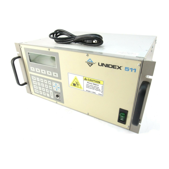
Aerotech UNIDEX 511 User Manual (476 pages)
Motion Controller
Brand:
Aerotech
| Category:
Controller
| Size: 4 MB
Table of Contents
Table of Contents
4
List of Figures
14
Chapter 1: Introduction
24
Overview of the UNIDEX 511 System
28
Figure 1-2. the UNIDEX 511 System Diagram
29
Ordering Information
30
Table 1-1. Basic Motion Controllers
30
Options and Accessories
31
Safety Procedures and Warnings
32
Getting Started
34
Chapter 2 : Getting Started
34
Introduction
34
UNIDEX 511 Setup Flowchart
35
Figure 2-1. Flowchart Overviewing the Installation/Configuration Process
35
Installing Cables and Wiring
36
Software Configuration Considerations
37
Special Startup Considerations
37
Feedback Verification
37
Limit Verification
38
Preliminary Servo Loop Setup
39
Table 2-1. Servo Loop Tuning Parameters
39
Enabling and Moving an Axis
40
Internal System Wiring
40
The User Interface
42
Chapter 3: The User Interface
42
Introduction
42
Control Panel
42
Figure 3-1. Control Panel
42
Power-Up Screen
44
Figure 3-3. U511 Menus Activated by the Function Keys
45
Program Menu
46
Program Menu: the Run Submenu
46
Figure 3-5. Load Program Screen
47
Figure 3-6. Running Program Screen
47
Program Menu: the Edit Submenu
48
Figure 3-9. Edit Command Screen
50
Figure 3-10. Specialized Command Edit Screen
51
Figure 3-11. "Save File As:" Screen
51
Figure 3-12. the ASCII Utility
52
The ASCII Utility
52
Figure 3-13. File Operations Screen
53
Program Menu: the Digitize Submenu
53
Program Menu: the File Submenu
53
Figure 3-14. Program Editor Screen, Digitize Menu
54
Figure 3-15. Joysticks Showing the "C" Button
55
Figure 3-16. Linear Digitizing Screen
56
Figure 3-17. Circular Digitizing Screen
56
Figure 3-18. Spline Command Screen
57
Setup Menu: Parameters
58
Figure 3-19. System Configuration Page (General Parameters)
59
Figure 3-20. Axis Configuration Page (Axis Parameters)
59
Figure 3-21. Fault Masks Page
60
Figure 3-22. Expanded Fault Masks Page
60
Setup Menu: the Fault Masks Page
60
Diagnostics Menu
61
Diagnostics Menu: Hardware Status Page
61
Figure 3-23. the Hardware Status Page
61
Diagnostics Menu: Primary I/O Page
62
Figure 3-24. Primary I/O Page
62
Table 3-1. Hardware Status Diagnostics
62
Diagnostics Menu: System Status Page
63
Figure 3-25. System Status Page
63
Table 3-2. Primary I/O Status Diagnostics
63
Diagnostics Menu: Position Page
64
Figure 3-26. the Position Page
64
Table 3-3. System Status Diagnostics
64
Diagnostics Menu: Active Limits Page
65
Figure 3-27. Active Limit Page
65
Table 3-4. Position Diagnostics
65
Table 3-5. Active Limit Diagnostics
65
Diagnostics Menu: Servo Faults Page
66
Figure 3-28. Servo Faults Page
66
Table 3-6. Servo Fault Diagnostics
66
Diagnostics Menu: Secondary I/O Page
67
Diagnostics Menu: Terminal Page
67
Figure 3-29. Secondary I/O Page
67
Table 3-7. Secondary I/O Diagnostics
67
Figure 3-30. Terminal Page
68
Table 3-8. Active Components of the Terminal Page
68
Tune Menu
69
Figure 3-31. Tune Screen
69
Troubleshooting Autotuning
71
MDI Menu
72
Figure 3-32. MDI Screen
72
Figure 3-33. Jstick Screen
73
Figure 3-34. Jog Screen
73
MDI Menu: Jog Submenu
73
MDI Menu: Joystick Submenu
73
MDI Menu: Commands Submenu
74
: Parameters
76
Chapter 4: Parameters
76
Introduction
76
Table 4-1. U511 Parameters Grouped by Page
76
System Configuration
82
Auto Enable Axes
82
Auto Run Program
82
Axis Calibration File
82
Firmware File
82
M-Code File
82
Parameter File
82
Global Subroutine File
83
PSO-PC DPRAM Address" (Hex Address 0Xnnnn)
83
PSO-PC Firmware File
83
Option Board Setup Code
84
PSO-PC I/O Address" (Hex Address 0Xnnn)
84
Safe Zone Output Bit 0,1-8
84
A/D Channel N Joystick Deadband" Parameters
85
Table 4-4. Joystick Deadband Parameters
85
User Interrupt Setup Code
85
A/D Channel N Center" Position Parameters
86
Enable Speaker
86
Table 4-5. Joystick Center Position Parameters
86
Abort on Input High 0, 1-16
87
Password
87
Pages 2 and 3: Serial Port #N Setup
88
Baud Rate" (Bits Per Second)
88
Data Bits" (7-8)
88
End of String Character
88
Fast Output?" (Y/N)
88
Parity" (N, O, E)
88
Stop Bits" (1-2)
88
Command ACK Character
89
Command NAK Character
89
Default Configuration
89
GPIB/IEEE-488 Setup
90
Default Configuration
90
EOS Character
90
GPIB Address" (0-30)
90
Parallel Pol Response Bit" (0-NONE or 1-8)
90
Time Out" (Seconds)
90
Axis Configuration
91
Metric (X00) and English (X01) Conversion Factors
91
Table 4-8. Relationship between Number of Decimal Digits Parameters and the Number of Programming Steps Per Programming Unit
92
Max Accel/Decel" (Machine Steps/Ms/Ms)
94
Positive (+) Move Is CW" (Y/N)
94
Enable Pause in Freerun" (Y/N)
95
Positive (+) Jog same as + Move" (Y/N)
95
Enable Axis Calibration" (Y/N)
96
Enable MFO in Freerun" (Y/N)
96
Table 4-14. Settings for Parameter X15
97
Table 4-15. Sample Calibration Table
98
In Position Deadband" (Machine Steps)
100
Backlash Correction Amount" (Machine Steps)
101
Joystick High Speed" (Machine Steps/Sec)
102
Table 4-21. Settings for Parameter X71
104
Table 4-23. Settings for Parameter X83
106
Table 4-24. Settings for Parameter X84
106
Servo Loop
107
Table 4-27. Bits of Parameter X78 and PID Loop Configuration
114
Table 4-28. Decimal Settings for Parameter X78
114
Homing and Limits
116
Figure 4-6. Typical Stage Showing CW and CCW Motor Rotation
117
Table 4-29. Settings for Parameter X02
117
Table 4-30. Settings for Parameter X03
118
Table 4-33. Settings for Parameter X09
120
Table 4-38. Settings for Parameter X77
123
Table 4-39. Motor Feedback Parameters
124
Table 4-40. Commutation Factors for 4, 6, and 8 Poles
128
Table 4-42. RDP Resolution and Setup Codes
130
Table 4-43. Settings for Parameter X38
131
Table 4-44. Settings for Parameter X39
132
Table 4-46. Settings for Parameter X41
134
Table 4-48. Sample Commutation Factors for AC Brushless Motors
136
Stepper High Current %" (0-100%) (Stepper Drives Only)
137
Microstepping Resolution" (Machine Steps) (Stepper Drives Only)
138
Stepper Correction" (Y/N) (Stepper Drives Only)
138
Stepper Low Current %" (0-100%) (Stepper Drives Only)
138
Base Speed" (Machine Steps/Ms) (AC Brushless Only)
139
Figure 4-8. Phase Advance Slope
139
Stepper Correction Speed" (Microsteps/Ms)
139
Base Speed Advance" (0-359 Degrees) (AC Brushless Only)
140
DAC Offset Parameters" (MV)
140
Phase Speed Advance" (0-359 Degrees) (AC Brushless Only)
140
Phase Speed" (Machine Steps/Ms) (AC Brushless Only)
140
Table 4-50. Settings for Parameters X79 and X80
140
Encoder Factor
141
Table 4-51. Settings for Parameter X82
141
Fault Masks
142
Introduction to Fault Masks
142
Table 4-52. Fault Mask Bit Descriptions
143
AUX Output
144
Disable
144
Global Fault Mask
144
Interrupt
144
Abort Motion
145
Enable Brake
145
Halt Queue
145
Top Feedrate" (Machine Steps/Ms)
146
Traps
146
Maximum Velocity Error" (0-8,388,607)
147
Maximum Position Error" (0-8,388,607)
148
Maximum Integral Error" (0-8,388,607)
149
RMS Current Trap" (0-100%)
150
RMS Current Sample Time" (1-16,383 Ms)
152
Clamp Current Output" (0-100%)
153
AUX Fault Output Bit" (0, 1-8)
154
Table 4-60. Settings for Parameter X54
154
Amplifier Fault Active Low" (Y/N)
155
Table 4-61. Settings for Parameter X70
155
Figure 4-10. Programming Control Using a Single Plane
156
Overview of Planes
156
Planes and Mapping
156
Figure 4-11. Programming Control Using Four Planes
157
Figure 4-12. Sample Programming Segment Showing the Use of Planes
158
Number of Contour Planes" (1, 2, or 4)
159
Keep Position after Reset?" (Y/N)
161
Figure 4-13. MFO Potentiometer with and Without Offsets
162
MFO Pot Offset" (0-255)
162
Axis {1, 2, 3, 4} Plane 1-4 as X, Y, Z, U
163
Axis {1,2,3,4} Gantry Yes/None Slave {1,2,3,4
165
Figure 4-14. Using "Home Offset" Parameter to Keep Gantry Aligned after Homing
167
Segment Time" (1-20 Ms)
168
Ramp Time" (1-32,000 Ms)
169
Default to Metric" (Yes/No)
170
Table 4-70. Parameter Associations between Planes, Measurement Units, and the Number of Decimal Digits
170
Figure 4-16. Graphs of Linear and Inverse Sine Ramping Trajectories
171
Linear Accel/Decel" (Y/N)
171
Contour Feedrate" (Program Steps/Ms)
172
Table 4-73. Point-To-Point Feedrate Parameter Assignments and Settings
172
X, Y, Z, and U Axes Index Feedrates" (Program Steps/Ms)
172
Clamp Feedrate" (Program Steps/Ms)
173
Corner Rounding Time" (1-32,000 Ms)
173
Contouring Mode
178
Direct Variables (V0 through V255)
181
Indirect Variables (VV0 through VV255)
181
Mathematical Function Commands
181
Table 5-2. Single Character Arguments for Programming
181
Functions
182
Operators and Evaluation Hierarchy
183
Table 5-3. Supported Functions
183
Relative Position Registers
184
System Registers
184
Absolute Position Registers
185
Real Time Feedback Position Registers
185
Table 5-6. Absolute Position Registers
185
Table 5-7. Real Time Feedback Position Registers
185
Real Time Command Position Registers
186
Table 5-8. Real Time Commanded Position Registers
186
Understanding the Concept of Program Steps
186
A/D Channel Registers
187
System Inputs $INP and $IN0-$INF
187
Table 5-9. A/D Channel Registers
187
Programming Commands
188
Table 5-10. UNIDEX 511 Programming Commands
190
Abort
192
Acceleration
192
Ac Pl (Accel Plane)
193
AFCO (Auto Focus)
194
Table 5-11. Optional Arguments
195
Again
197
AT (Autotune)
198
Beep
199
Board
199
Brake
200
CAL (Load Calibration File)
201
CLOCKWISE and COUNTERCLOCKWISE CIRCULAR
201
Interpolation
201
CI (Command Interrupt)
205
CLRSCR (Clear Screen)
205
CM (Contouring Mode)
206
COMREC (Strings in Port)
207
COMVAR (String to Variable)
208
CS (Command Scope)
209
Cutter Compensation Commands
210
Figure 5-1. Startup Moves
210
Figure 5-2. Ending Moves
211
CVI (Convert to Integer)
213
Cycle
213
DAC (D/A Output)
214
Figure 5-4. CYCLE START Function
214
Disable
215
DS (Display Servo Loop Data)
216
Dwell
217
DY (Dynamic Gain)
217
Enable
218
Error
219
Exit
220
Fault Acknowledge
221
FL (Filter Time Constant)
221
Freerun
222
Gain
223
Gear
224
Goto
225
Figure 5-5. Sample Uses of the GOTO Command
226
Halt
226
Home
227
Index
229
Inn (Read Inputs)
230
Interrupt
231
IO (Set/Read 8 X 3 I/O)
231
IOSET (Setup 8 X 3 I/O)
232
Jog
233
Label Marker (:)
233
Linear
234
Loop
235
Lvdt
236
M0 (M Zero)
237
Map
237
MCOMM (Motor Commutation)
238
Message
239
MR (Memory Read)
240
MSET (Motor Setup)
241
Table 5-14. Motor Phase Labels and Hall States
242
MW (Memory Write)
243
Next
244
Oen (Extended Output)
244
Output
245
Parallel
246
Prm (Parameter Read)
246
Pause
247
Plane
248
Program
249
Queue
251
Ramp
253
Reference
254
Return
254
ROTATE (Part Rotation)
254
Figure 5-8. Illustration of no Corner Rounding (G24)
255
Rounding
255
SCF (Overriding Scale Factor)
256
Segment
258
SKEY (Soft Keys)
259
Figure 5-10. Optional UNIDEX 511 Joystick, JI Model Left, JBV Model Right
260
Slew
260
Software
262
Spline
263
Start
264
Subroutine
265
Sync
266
Target Tracking Commands (TE, TD, TP)
266
Trajectory
267
Trigger
268
UMFO (Manual Feed Override)
269
VAR (Read/Write Variables)
270
Velocity
271
Correct Usage and Limitations of the Velocity Profiling Algorithm
272
Figure 5-11. Plot of Velocity Without Velocity Profiling
272
Figure 5-12. Plot of Velocity with Velocity Profiling
272
Figure 5-13. Short Middle Move with no Velocity Profiling
273
Figure 5-15. same Motion with Ramping Time Reduced
274
Figure 5-16. Circular Profiling with Long Ramp Time
274
Figure 5-17. Circular Profiling with Short Ramp Time
274
CM1 Contouring Mode
275
Figure 5-18. Two Axis Linear Move with Velocity Profiling
275
Figure 5-21. Velocity Profile Without a G9 Command at the End of the Sequence
278
Wait
279
While/Endwhile
280
Chapter 5 : Programming Commands
181
Chapter 6: Remote Mode Operations
282
GPIB IEEE-488 Interface
282
COM1 and COM2) Interface
282
Troubleshooting Remote Communications
283
Command Handshake Mode (RS-232 Only)
283
Remote Commands
283
Enable RS-232 Remote Communications
283
Program Execution
284
Table 6-1. Enable RS-232 Remote Mode Sequence
284
Table 6-2. Auto Run a Program Communication Sequence
284
PA: Program Abort
285
Service Request Mode (SRQ)
286
Table 6-5. Service Request on Sequence
286
Hold/Trigger/Cancel
288
Table 6-10. Disable Hold Mode Sequence
288
Table 6-9. Enable Hold Mode Sequence
288
PE: Print Error Message String
289
Table 6-11. Trigger Command Sequence
289
Table 6-12. Print Error Message Sequence
289
I: Execute Immediate Command
290
Table 6-13. Immediate Command Sequence
290
Fmn: Format of Returned Data
291
Table 6-14. Format of Return Data Command Sequence
291
Pxn, Pyn, Pzn, Pun: Axis Positions
292
Table 6-15. Values of "N" and Feedback Type for the Axis Positions Commands
292
Table 6-16. Print Axis Position Sequence
292
Q: Serial Pol Command
293
Table 6-17. Status Byte Bit Assignments
293
Psn: Print Status
294
Table 6-18. Serial Pol Sequence
294
Table 6-19. Values of "N" and Corresponding Status for the Psn Command
294
Rrn/Wrn,Val: Read / Write Register
297
Table 6-20. Print Status Sequence
297
Table 6-21. Read Register Sequence
297
Table 6-22. Write Register Sequence
298
Parameter Editing
299
Table 6-24. Write Parameter Sequence
299
Table 6-25. Read Parameter Sequence
299
RE: Hardware Reset
300
Table 6-26. Save Parameters Sequence
300
Table 6-27. Hardware Reset Sequence
300
File Transfers
301
Table 6-28. Upload File Sequence
302
PD: Print Directory
303
Table 6-29. Sequence of Commands When Downloading Files
303
Table 6-30. Print Directory Sequence
303
Ppfile: Print Program "File" to Port
304
Rvn: Read Variable
304
Table 6-31. Print Program "File" Sequence
304
Table 6-32. Read Variable Sequence
304
Dffilename: Delete File
305
HE [CMD]: Help Menu
305
Table 6-33. Delete File Sequence
305
Table 6-34. Help Menu Command Sequence
305
GV: Software Version
306
Table 6-35. Software Version Command Sequence
306
UNIDEX 511 Remote Timing
307
Figure 6-1. Plot Showing Signals Generated by a GPIB Command
307
C Program Example
308
Figure 6-2. Receive and Transmit Lines During Transfer at 9600 Baud
308
Chapter 7 : Windows Interface and Utilities
312
Introduction
312
UNIDEX 511 Parameter Editor
313
Figure 7-2. the Cascaded Transfer Menu
314
Figure 7-3. Transfer Parameter Values between Axes Popup
314
Edit Parameters: the Number, Value, and Axis Fields
315
Figure 7-4. Transfer Parameter Values between Planes Popup
315
UNIDEX 511 Axis Scope Utility
316
UNIDEX 511 Diagnostics Screen
316
Figure 7-5. the Diagnostics Window
316
Table 7-1. Software Status Diagnostics
318
Table 7-2. Axis Position Diagnostics
318
Table 7-3. Hardware Status Diagnostics
318
UNIDEX 511 File Transfer Utility
320
Loading System Software
320
Manufacturing Mode
320
Erasing B Drive
321
Loading DOS or BIOS
321
Uploading a File (to UNIDEX 511)
321
Downloading a File (from UNIDEX 511)
322
Chapter 8: Tuning Servo Loops
325
Figure 8-1. UNIDEX 511 Servo Loop
325
Axis Scope Tuning Window
326
Figure 8-2. Axis Scope Window
326
Table 8-1. Menu Items on the Axis Scope Window
326
Table 8-2. File Menu Options in Axis Scope
327
The File Menu
327
The Remote Menu
327
The Plot Menu
328
The Trigger Menu
328
Table 8-3. Trigger Menu Options in Axis Scope
329
The Collect Menu
329
The Display Menu
329
The Axis Menu
330
The Tools Menu
330
The Units Menu
330
The Axis Scope Toolbars
331
Aff" Acceleration Feedforward Gain
332
Ki" Integral Gain
332
Kp" Proportional Gain
332
Kpos" Position Gain
332
Vff" Velocity Feedforward Gain
332
Autotuning
333
Bandwidth and Damping
333
Setting up an Excitation
333
Specifying Desired Performance
333
Autotuning Procedure
335
Figure 8-6. Autotune Plot Where "Dist" Has Been Set too Low
336
Figure 8-7. Autotune Plot Where "Dist" Has Been Set too High
336
Dual Loop Systems
337
Figure 8-8. Autotune Plot Showing Proper Calibration
337
Guidelines and Limitations
337
Table 8-4. Troubleshooting the Autotune Process
338
Troubleshooting Autotuning
338
Figure 8-9. Flowchart of Overall Tuning Process
339
Tuning Procedure for Servo Loops
339
Figure 8-10. the Faults Tab of the Parameter Editor
340
Figure 8-11. Servo Loop Tab of the Parameter Editor
341
Table 8-5. Initial Servo Parameter Values
341
Figure 8-12. MAXIMIZE Button on the Axis Scope Window
342
Figure 8-13. Unacceptable Velocity Error
343
Figure 8-14. Acceptable Velocity Error (When Adjusting "Kp")
344
Figure 8-15. Proper Adjustment of "KI
344
Figure 8-16. Oscillation in Position Error When "Ki" Is too High
345
Figure 8-17. Plot Showing an Appropriate Value for "Kpos
346
Figure 8-18. Plot Showing Overall Effects When "Kpos" Is High
346
Tuning Tips
347
In-Position Integrator
348
Tuning with Tachometer Feedback
348
Velocity Feed Forward
348
Servo Parameter Setup for Tachometer Feedback
349
The Axis Scope Toolbars
349
Figure 8-20. Faults Tab of the Parameter Editor
352
Figure 8-21. Servo Loop Tab of the Parameter Editor
353
Table 8-7. Initial Servo Parameter Values - Tach Tuning
353
Figure 8-24. Axis Scope Window Showing "Kpos" too Low
356
Figure 8-25. Plot Showing a Roughly Tuned Axis (When Adjusting "Kpos")
357
Figure 8-26. Plot Showing the Removal of DC Offsets in the Position Error
358
Figure 8-27. O-Scope Showing Current Feedback for One Move
359
Figure 8-28. Plot Illustrating Smoothness in the Position Error
360
Figure 8-29. Plot Showing Effects on Position Error (When "Ki" Is too High)
361
Figure 8-30. Plot of the Position Error with Appropriate "Ki" Value
361
Figure 8-31. Position Error after Increasing "Vff
362
Figure 8-32. Position Error Reduced to Within 10 Counts of Error Using "Vff
362
Figure 8-33. Plot of Position Error When "Vff" Is too High
363
Programming Examples
364
Chapter 9: Programming Examples
365
Figure 9-1. Sample Path for Incremental (Relative) Motion Demonstration
365
Incremental (Relative) Motion with Velocity Profiling
365
Absolute Motion with Velocity Profiling
368
Figure 9-2. Sample Path for Absolute Motion Example Using Velocity Profiling
368
CNC Demonstration Using Velocity Profiling, Linear, and Circular Interpolation
370
Corner Rounding
371
Figure 9-3. Sample Path of Square with and Without the Rounding Feature
371
GEAR Demonstration of a Master Axis with Two Slave Axes
373
Figure 9-4. Output from Splining Example
375
Splining
375
Part Rotation
377
Figure 9-6. Output from Overriding Scale Factor Example Program
381
Softkey Use
382
I/O Bus Program
383
Power on Subroutine/Global Subroutine File
384
Figure 10-1. Typical Input for CW Limit, CCW Limit, Home Limit, and Hall Effect Inputs HA, HB, HC
386
Figure 10-2. Rear View Showing Various Connectors
387
Table 10-1. Encoder Connector Pinouts for Axis 1 through 4 (J2 - J5)
388
Table 10-2. COM1 Interface Connector Pinouts
388
Table 10-3. COM2 Interface Connector Pin Connections
389
Table 10-4. 16 IN/8 out Connector
390
Table 10-5. UNIDEX 511/Opto 22 Connection Information
391
Figure 10-3. Electrical Characteristics of the UNIDEX 511 Opto 22 Connections
393
Table 10-6. 8 X 3 I/O Bus Connector Pinouts (J12)
395
Figure 10-4. Opto-Isolated Inputs
396
Table 10-7. Control Board Current Limiting Resistor Locations for Opto-Isolated Inputs
396
Figure 10-5. Opto-Isolated Outputs
397
Table 10-8. Opto-Isolated Output Pin Locations
397
Table 10-9. aux I/O Connector Pinouts (J10)
398
Figure 10-6. the UINT Opto-Isolated Input
399
Figure 10-7. Electrical Characteristics of the UNIDEX 511 Emergency Stop Interface
399
Table 10-10. External Voltages and Resistances for the Emergency Stop Input
400
Table 10-11. Joystick Interface Connector Pinouts (J6)
400
Table 10-14. Control Board Jumper "JP" Description (JP1-JP15)
402
Figure 10-8. Control Board Showing Locations of User Configurable Jumpers
403
Table 10-15. Interface Board Jumper "JP" Description (JP1-JP46)
404
Figure 10-9. Interface Board Showing Locations of User Configurable Jumpers
405
Table 10-18. U511 Control Board 'PSO Encoder Bus' Connector Pinouts (P6)
408
Table 10-19. Electrical Specifications
410
Troubleshooting
412
Chapter 11 : Troubleshooting
413
Stepper Motors and Related Problems
413
Table 11-1. Troubleshooting for Stepper Motors (and Related) Problems
413
Servo Related Problems
415
Table 11-3. Troubleshooting for Problems Involving Fault Conditions
416
Problems Involving Fault Conditions
416
Communications Related Problems
418
Homing Related Problems
418
Table 11-4. Troubleshooting for Homing Related Problems
418
Table 11-5. Troubleshooting for RS-232 Related Problems
418
Fuse Replacement
419
Table 11-6. Troubleshooting for IEEE-488/GPIB Related Problems
419
Table 11-7. Fuse Replacement Part Numbers
419
Battery
420
Cleaning
420
Preventative Maintenance
420
Table 11-8. Preventative Maintenance
420
Figure C-1. Page 7-U511 Diagnostics Window
436
Table C-1. Hall State Table
436
Figure D-1. an Isbx-IO48 Card Connected to Two I/O Cards
438
Figure D-2. the Isbx-IO48 Card
439
Table D-1. Isbx-IO48 Pinouts
439
Figure D-3. Isbx-IO48 Pinouts on the PB24 I/O Card
441
Table D-2. Isbx-IO48 Control Words
442
Table F-1. System Commands Supported by the U511
448
Table F-2. Motion/Flow Commands Supported by the U511
449
Table G-7. Bit Resolution Configuration; RCN1 through RCN4 on RDP Board
456
Figure G-2. RDP Board Connection to UNIDEX 511 Board
457
Table G-8. Setting "Position Channel" (X38) for the RDP Board
458
Table G-9. Setting "Primary Feedback Setup Code" (X40) for the RDP Board
458
Figure G-3. Mating DB37 Connector
459
Table G-10. RDP Board Pinouts
459
Figure G-4. Suggested Cabling from RDP Board to Resolver or Inductosyn
460
Figure G-5. Rectified Signals with the most Ideal Signal
462
Advertisement
Advertisement
Related Products
Aerotech UNIDEX 500
Aerotech UNIDEX U100i
Aerotech UNIDEX 100
Aerotech UNIDEX 600 Series
Aerotech UNIDEX 650
Aerotech UNIDEX 11
Aerotech LaserTurn 5-ASR
Aerotech 6020HRJ
Aerotech 8030J
Aerotech A3200 Series
Aerotech Categories
Industrial Equipment
DC Drives
Controller
Engine
Amplifier
More Aerotech Manuals
Login
Sign In
OR
Sign in with Facebook
Sign in with Google
Upload manual
Upload from disk
Upload from URL