Advertisement
Quick Links
92130300
2014 GM 1500 Pickup Front 2.5" Kit
Thank you for choosing Rough Country for all your suspension needs.
Rough Country recommends a certified technician install this system. In addition to these instructions, professional
knowledge of disassemble/reassembly procedures as well as post installation checks must be known. Attempts to install
this system without this knowledge and expertise may jeopardize the integrity and/or operating safety of the vehicle.
Please read instructions before beginning installation. Check the kit hardware against the parts list on this page. Be sure
you have all needed parts and know where they go. Also please review tools needed list and make sure you have
needed tools.
PRODUCT USE INFORMATION
As a general rule, the taller a vehicle is, the easier it will roll. Seat belts and shoulder harnesses should be worn at all
times. Avoid situations where a side rollover may occur.
Generally, braking performance and capability are decreased when larger/heavier tires and wheels are used. Take this
into consideration while driving. Do not add, alter, or fabricate any factory or after-market parts to increase vehicle height
over the intended height of the Rough Country product purchased. Mixing component brands is not recommended.
Rough Country makes no claims regarding lifting devices and excludes any and all implied claims. We will not be re-
sponsible for any product that is altered.
This suspension system was developed using a 285/70/17, tire with factory wheels. Note if wider tires are used, offset
wheels will be required and trimming will be required.
**Note** The electric power steering must be unplugged before any of the steering components are removed. Failure to
do so may cause damage to the electric power steering.
If you have any questions concerning the design, function, and correct use of our products please contact us at 800-222-
7023.
NOTICE TO DEALER AND VEHICLE OWNER
Any vehicle equipped with any Rough Country product should have a "Warning to Driver" decal installed on the inside of
the windshield or on the vehicle's dash. The decal should act as a constant reminder for whoever is operating the vehi-
cle of its unique handling characteristics.
INSTALLING DEALER - it is your responsibility to install the warning decal and forward these installation instructions on
to the vehicle owner for review. These instructions should be kept in the vehicle for its service life.
Advertisement

Related Manuals for rough country 92130300


Summary of Contents for rough country 92130300
- Page 1 Rough Country product purchased. Mixing component brands is not recommended. Rough Country makes no claims regarding lifting devices and excludes any and all implied claims. We will not be re- sponsible for any product that is altered.
-
Page 2: Installation Instructions
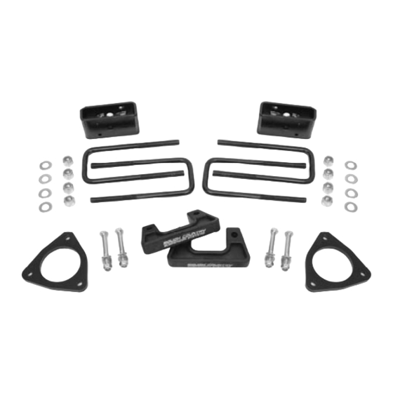
Tools Needed: Kit Contents: 18mm Wrench 2- Lower Strut Extensions 15mm Socket 2– Upper strut spacers 15mm Wrench 2- 2” Rear Blocks 17mm Wrench 4– 9/16 U- Bolts 21mm Wrench 1307 Kit Bag 7/32 Allen Wrench 4- 10x1.5x80mm bolts Flat Screwdriver 8- SAE Flat washers Hammer 4-10mm nuts... - Page 3 8. Using a 15mm wrench or socket remove the bolts from the bottom strut mount. See Photo 5 9. Remove the bolt clips from the bottom of the strut using a flat screw driver. See Photo 6 Photo 5 Photo 6 Photo 7 Photo 8 10.
-
Page 4: Rear Installation
18. Reinstall the steering linkage nut using a 21mm wrench. If ball joint turns while tightening, use a 10mm wrench to hold the bottom of the tie rod. See Photo 12 Photo 11 Photo 12 19. Repeat steps 3-14 on opposite side of vehicle Reconnect the three plugs going to the electric power steering. -
Page 5: Product Use Information
NOTICE TO DEALER AND VEHICLE OWNER Any vehicle equipped with any Rough Country product should have a “Warning to Driver” decal installed on the inside of the windshield or on the vehicle’s dash. The decal should act as a constant reminder of the vehicles unique handling characteristics. - Page 6 FRONT INSTALLATION INSTRUCTIONS 1. Disconnect battery using a10mm socket 2. Using a screwdriver disconnect the air filter inlet hose from air box. See Photo 1. Lock the steering wheel and mark upper and lower steering shaft. Remove steering shaft from rack and pinion using a 11mm socket. 3.
- Page 7 7. Remove the side bumper support bracket using a 15mm socket . See Photo 7. 8. Unplug the fog lights and wiring harness from bumper. See Photo 8. PHOTO 7 PHOTO 8 9. Use a 18mm socket to remove the four bolts holding the bumper on to the frame then remove bumper. See Photo 9. 10.
- Page 8 13. The other ground wire is on passenger side body mount behind the tire. See Photo 13. 14. Remove the O2 sensor wire clip from frame just above passenger side body mount. On driver side remove the wir- ing loom bracket using a 13mm socket. See Photo 14. Remove the wire clips from the top of strut bolts. PHOTO 14 PHOTO 13 15.
- Page 9 18. Once the bushing is out knock the two studs out using a hammer and vise. See Photo 19. Replace the two stud with the supplied 3/8” x 2.25” bolts, washers, and nuts. Install cab body puck on body bushing and place on truck. See Photo 20.
- Page 10 22. On the front frame horns measure the tow hook mounting hole on the side with only one hole 1 1/2” back and 1 3/16” up from bottom of frame. See Photo 23. Mark the area and drill a new hole for the tow hooks using a 1/2 drill. Flip the tow hooks and install bolts.
- Page 11 25. On the inside of the front bumper where the tow hooks holes are measure 1/4 down on the inner bumper bracket and cut even with the sides of the holes. See Photo 29. 26. Install front bumper using stock hardware with the supplied 12mm nuts. Use a 18mm socket and wrench to tighten bumper bolts.
- Page 12 BED/REAR BUMPER INSTALLATION INSTRUCTIONS **Note** The bumper is removed in the first three pictures to help show locations for the bolts and electrical plugs. The bumper is not removed until step 3. 1. Loosen the 8 bolts holding the bed on using a 18mm socket. See Photo 1. Remove the six rear bolts on bed leav- ing the front bolts near cab in but loose.
- Page 13 5. Using a torx 15 to remove lower bumper screws from the plastic bumper cover. See Photo 6. 6. Using a 7mm socket remove the screws from the inside of bumper. See Photo 7. PHOTO 6 PHOTO 7 7. Using a screwdriver remove the metal clips from the plastic bumper cover. There will be five metal clips to be re- moved.
- Page 14 11. Install new bumper brackets using stock hardware and a 40 torx to tighten. See Photo 12. 12. Reassemble rear bumper 13. Remove the body puck from the rear of bed that was place to help remove the bumper and install the bed bolts on one side of the truck to hold the bed in place while installing bed pucks.
- Page 16 Kit Picture Thank you for choosing Rough Country.
Need help?
Do you have a question about the 92130300 and is the answer not in the manual?
Questions and answers