Table of Contents
Advertisement
Quick Links
S
SC825TQC-R740LPB
SC825TQ-R740UB
SC825TQ-R720LPB
SC825TQ-R720UB
SC825TQ-R700U(V)(B)
SC825TQ-600LPB
SC835TQ-600WB
SC825TQ-560LP(V)(B)
SC825TQ-R500WB
USER'S MANUAL
UPER
SC825 CHASSIS
Series
SC825TQC-R740WB
SC825TQ-R740LPB
SC825TQ-R740WB
SC825TQ-710LP
SC825TQ-R700LP(V)(B)
SC825TQC-600LPB
SC825TQC-600WB
SC825TQ-563UB
SC825TQ-563LPB
SC825TQ-560U(V)(B)
2.0b
®
Advertisement
Table of Contents

Related Manuals for Supero SC825 Series


Summary of Contents for Supero SC825 Series
- Page 1 UPER ® SC825 CHASSIS Series SC825TQC-R740WB SC825TQC-R740LPB SC825TQ-R740LPB SC825TQ-R740UB SC825TQ-R740WB SC825TQ-R720LPB SC825TQ-710LP SC825TQ-R720UB SC825TQ-R700LP(V)(B) SC825TQ-R700U(V)(B) SC825TQC-600LPB SC825TQ-600LPB SC825TQC-600WB SC835TQ-600WB SC825TQ-563UB SC825TQ-560LP(V)(B) SC825TQ-563LPB SC825TQ-R500WB SC825TQ-560U(V)(B) USER’S MANUAL 2.0b...
- Page 2 SC825 Chassis Manual Preface The information in this User’s Manual has been carefully reviewed and is believed to be accurate. Preface The vendor assumes no responsibility for any inaccuracies that may be contained in this document, makes no commitment to update or to keep current the information in this manual, or to notify any person or organization of the updates.
-
Page 3: Table Of Contents
SC825 Chassis Manual Preface Table of Contents Manual Organization Chapter 1 Introduction Chapter 1 Introduction Overview ......................1-1 The first chapter provides a checklist of the main components included with this Shipping List ....................1-1 chassis and describes the main features of the SC825 chassis. This chapter also Chassis Features .................... - Page 4 SC825 Chassis Manual Preface Chapter 4 System Interface Rack Mounting Considerations ............... 6-3 Ambient Operating Temperature ..............6-3 Overview ......................4-1 Reduced Airflow ..................6-3 Control Panel Buttons ..................4-2 Mechanical Loading ................... 6-3 Control Panel LEDs ..................4-2 Circuit Overloading ..................6-3 Drive Carrier LEDs ..................
- Page 5 SC825 Chassis Manual Notes viii...
-
Page 6: Chapter 1 Introduction
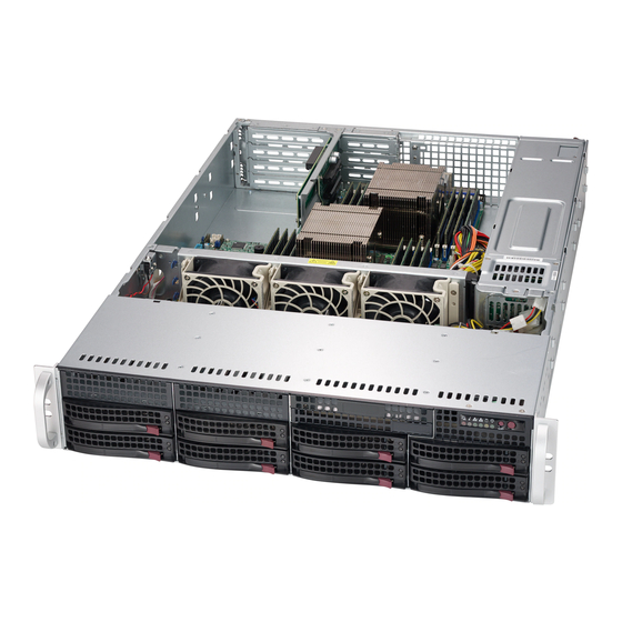
Chapter 1: Introduction Chapter 1 Introduction Overview Supermicro’s SC825 2U chassis features a unique and highly-optimized design. The chassis is equipped with high efficiency power supply. Shipping List Please visit the following link for the latest shipping lists and part numbers for your particular chassis model www.supermicro.com SC825 Chassis Model... -
Page 7: Chassis Features
SC825 Chassis Manual Chapter 1: Introduction Chassis Features SC825 Chassis SC825TQ-600LPB 8x SAS/SATA 7x LF 600W The SC825 2U, high-performance chassis includes the following features: SC825TQ-563LPB 7x LF / 3x FF, 3 8x SAS/SATA 560W / SC825TQ-563UB LP, 1 UIO Hard Drives SC825TQ-560UV / 8x SAS/SATA... -
Page 8: Contacting Supermicro
SC825 Chassis Manual Chapter 1: Introduction Contacting Supermicro Returning Merchandise for Service A receipt or copy of your invoice marked with the date of purchase is required be- Headquarters fore any warranty service will be rendered. You can obtain service by calling your Address: Super Micro Computer, Inc. - Page 9 SC825 Chassis Manual Notes...
-
Page 10: Chapter 2 Standardized Warning Statements For Ac Systems
Chapter 2: Warning Statements for AC Systems Chapter 2 Standardized Warning Statements for AC Systems About Standardized Warning Statements The following statements are industry standard warnings, provided to warn the user of situations which have the potential for bodily injury. Should you have questions or experience difficulty, contact Supermicro's Technical Support department for assistance. - Page 11 SC825 Chassis Manual Warning Statements for AC Systems Warnung جسذٌة اصابة ًتتسبب ف حالة ٌوكي أى ًاًك ف خطز ًٌٌع هذا الزهز !تحذٌز WICHTIGE SICHERHEITSHINWEISE الذوائز بالوخاطز الٌاجوة عي ي على علن ، ك هعذات تعول على أي قبل أى Dieses Warnsymbol bedeutet Gefahr.
-
Page 12: Installation Instructions
SC825 Chassis Manual Chapter 2: Warning Statements for AC Systems Installation Instructions Circuit Breaker Warning! Warning! This product relies on the building's installation for short-circuit (overcurrent) Read the installation instructions before connecting the system to the power source. protection. Ensure that the protective device is rated not greater than: 250 V, 20 A. 設置手順書... -
Page 13: Power Disconnection Warning
SC825 Chassis Manual Chapter 2: Warning Statements for AC Systems ¡Advertencia! 경고! El sistema debe ser disconnected de todas las fuentes de energía y del cable 이 제품은 전원의 단락(과전류)방지에 대해서 전적으로 건물의 관련 설비에 eléctrico quitado de los módulos de fuente de alimentación antes de tener acceso 의존합니다. -
Page 14: Equipment Installation
SC825 Chassis Manual Chapter 2: Warning Statements for AC Systems Equipment Installation Waarschuwing Deze apparatuur mag alleen worden geïnstalleerd, vervangen of hersteld door Warning! geschoold en gekwalificeerd personeel. Only trained and qualified personnel should be allowed to install, replace, or service Restricted Area this equipment. -
Page 15: Battery Handling
SC825 Chassis Manual Chapter 2: Warning Statements for AC Systems Warnung אזור עם גישה מוגבלת Bei Einsetzen einer falschen Batterie besteht Explosionsgefahr. Ersetzen Sie die Batterie nur durch den gleichen oder vom Hersteller empfohlenen Batterietyp. !אזהרה Entsorgen Sie die benutzten Batterien nach den Anweisungen des Herstellers. יש... -
Page 16: Redundant Power Supplies
SC825 Chassis Manual Chapter 2: Warning Statements for AC Systems Redundant Power Supplies امداد الطاقة بوحدات عدة اتصاالت جهاز ال يكون لهذا قد الكهرباء عن وحدة ال لعسل كافة االتصاالت يجب إزالة 경고! Warning! This unit might have more than one power supply connection. All connections must 이... -
Page 17: Comply With Local And National Electrical Codes
SC825 Chassis Manual Chapter 2: Warning Statements for AC Systems Attention מתח בפנל האחורי L'équipement doit être installé conformément aux normes électriques nationales et locales. !הרה אז קיימת סכנת מתח בפנל האחורי בזמן תפעול המערכת. יש להיזהר במהלך תיאום חוקי החשמל הארצי .העבודה... -
Page 18: Hot Swap Fan Warning
SC825 Chassis Manual Chapter 2: Warning Statements for AC Systems ¡Advertencia! 警告 當您從機架移除風扇裝置,風扇可能仍在轉動。小心不要將手指、螺絲起子和其他 Al deshacerse por completo de este producto debe seguir todas las leyes y 物品太靠近風扇。 reglamentos nacionales. Warnung Attention Die Lüfter drehen sich u. U. noch, wenn die Lüfterbaugruppe aus dem Chassis La mise au rebut ou le recyclage de ce produit sont généralement soumis à... -
Page 19: Power Cable And Ac Adapter
SC825 Chassis Manual Chapter 2: Warning Statements for AC Systems Power Cable and AC Adapter Attention Lors de l'installation du produit, utilisez les bables de connection fournis ou désigné. L'utilisation d'autres cables et adaptateurs peut provoquer un dysfonctionnement Warning! ou un incendie. Appareils électroménagers et de loi sur la sécurité Matériel interdit When installing the product, use the provided or designated connection cables, l'utilisation de UL ou CSA câbles certifiés qui ont UL ou CSA indiqué... - Page 20 SC825 Chassis Manual Notes 2-20...
-
Page 21: Overview
Chapter 3: Chassis Components Chapter 3 Chassis Components Overview This chapter describes the most common components included with your chassis. Some components listed may not be included or may not be compatible with your particular chassis model. For more information, see the installation instructions detailed later in this manual. -
Page 22: Power Supply
SC825 Chassis Manual Power Supply Each SC825 chassis model includes a high-efficiency power supply rated at 500W (redundant), 560W (single), 563W (single) 600W (single), 700W (redundant) 710W (single), 720W (redundant) or 740W (Redundant). In the unlikely event your power supply fails, replacement is simple and can be accomplished without tools. Air Shroud Air shrouds are shields, usually plastic, which conduct the airflow directly to where it is needed. -
Page 23: Chapter 4 System Interface
Chapter 4: System Interface Chapter 4 System Interface Overview There are LEDs on the control panel and the drive carriers to keep you constantly informed of the over-all status of the system, as well as the activity and health of specific components. -
Page 24: Control Panel Buttons
SC825 Chassis Manual Chapter 4: System Interface Control Panel Buttons Information LED Status Description There are two push-buttons located on the front of the chassis. These are (in order Continously on and red An overheat ocondition has occured. (This may be from left to right) a reset button and a power on/off button. -
Page 25: Drive Carrier Leds
SC825 Chassis Manual Drive Carrier LEDs Your chassis uses SAS/SATA drives. SAS/SATA Drives Each SAS/SATA drive carrier has two LEDs. Green: Each Serial ATA drive carrier has a green LED. When illuminated, this green LED (on the front of the SATA drive carrier) indicates drive activity. A con- nection to the SATA backplane enables this LED to blink on and off when that particular drive is being accessed. -
Page 26: Chapter 5 Chassis Setup And Maintenance
Chapter 5: Chassis Setup and Maintenance Chapter 5 Chassis Setup and Maintenance Overview This chapter covers the steps required to install components and perform mainte- nance on the chassis. The only tool you will need to install components and perform maintenance is a Phillips screwdriver. -
Page 27: Removing The Chassis Cover
SC825 Chassis Manual Chapter 5: Chassis Setup and Maintenance Removing the Chassis Cover Installing Hard Drives Remove Screw Remove Screw Release Tab Figure 5-1. Removing the Chassis Cover Removing the Chassis Cover 1. Power down the system and remove the power cords from the rear of the power supply. - Page 28 SC825 Chassis Manual Chapter 5: Chassis Setup and Maintenance Dummy Drive SAS/SATA Hard Drive Drive Carrier Figure 5-3. Chassis Drive Carrier The drives are mounted in drive carriers to simplify their installation and removal from the chassis. These carriers also help promote proper airflow for the drive Drive Carrier bays.
-
Page 29: Installing An Optional Fixed Hard Drive
SC825 Chassis Manual Chapter 5: Chassis Setup and Maintenance Installing an Optional Fixed Hard Drive DVD-ROM Replacement or Installation The SC825 chassis models include two open slots for optional hard disk drives. To Most SC825 chassis models include a DVD-ROM which is usually pre-installed. utilize these slots, the dummy drive and the slot cover must be removed. -
Page 30: Installing The Motherboard
SC825 Chassis Manual Chapter 5: Chassis Setup and Maintenance Installing the Motherboard Permanent and Optional Standoffs Standoffs prevent short circuits by securing space between the motherboard and the chassis surface. The SC825 chassis includes permanent standoffs in locations I/O Shield used by most motherboards. -
Page 31: Expansion Card Pci Slot Setup
SC825 Chassis Manual Chapter 5: Chassis Setup and Maintenance Installing the Motherboard Expansion Card PCI Slot Setup SC825: The chassis includes PCI slots for expansion cards. The number of cards 1. Review the documentation that came with your motherboard. Become familiar you can use depends on your chassis model. -
Page 32: Pci Slot Setup For Sc825U (Universal Output) And Sc825W
SC825 Chassis Manual Chapter 5: Chassis Setup and Maintenance Installing the Air Shroud PCI Slot Setup for SC825U (Universal Output) and SC825W SC825U and SC825W chassis accepts a slightly smaller "L" shaped motherboard to allow for a universal expansion card. This universal output card allows the systems to accept SAS, SCSI, IB, Ethernet, and other types of connections. -
Page 33: Checking The Server's Airflow
SC825 Chassis Manual Chapter 5: Chassis Setup and Maintenance System Fans Three heavy duty fans provide cooling for the chassis. These fans circulate air through the chassis as a means of lowering the chassis internal temperature. Release Tab Figure 5-14. System Fan Figure 5-13. -
Page 34: 5-10 Power Supply
SC825 Chassis Manual Chapter 5: Chassis Setup and Maintenance 5-10 Power Supply Depending on your chassis model, the SC825 Chassis has a 560, 600, 700, 710, 720 or 740 Watt power supply. This power supply is auto-switching capable. This enables it to automatically sense and operate at a 100v to 240v input voltage. An amber light will be illuminated on the power supply when the power is off. -
Page 35: Replacing The Power Distributor
SC825 Chassis Manual Chapter 5: Chassis Setup and Maintenance Release Tab Figure 5-17. Replacing the Power Distributor Replacing the Power Distributor Redundant server chassis that are 2U or greater require a power distributor. The power distributor provides failover and power supply redundancy. In the unlikely event you must replace the power distributor, do following 1. -
Page 36: Replacing Or Installing The Front Port Panel
SC825 Chassis Manual Chapter 5: Chassis Setup and Maintenance 5-11 Optional Front Bezel Replacing or Installing the Front Port Panel Replace or Install the Front Port Panel The SC825 chassis supports an optional full-face locking front bezel for added se- curity. - Page 37 SC825 Chassis Manual Notes 5-22...
-
Page 38: Overview
Chapter 6: Rack Installation Chapter 6 Rack Installation Overview This chapter provides a quick setup checklist to get your chassis up and running. Following these steps in the order given should enable you to have the system operational within a minimum amount of time. Unpacking the System You should inspect the box the chassis was shipped in and note if it was damaged in any way. -
Page 39: Rack Precautions
SC825 Chassis Manual Chapter 6: Rack Installation Rack Precautions Rack Mounting Considerations • Ensure that the leveling jacks on the bottom of the rack are fully extended to the floor with the full weight of the rack resting on them. Ambient Operating Temperature If installed in a closed or multi-unit rack assembly, the ambient operating tempera- •... -
Page 40: Rack Mounting Instructions
SC825 Chassis Manual Chapter 6: Rack Installation Rack Mounting Instructions This section provides information on installing the SC825 chassis into a rack unit with the quick-release rails provided. There are a variety of rack units on the market, which may mean the assembly procedure will differ slightly. You should also refer to the installation instructions that came with the rack unit you are using. -
Page 41: Outer Rack Rails
SC825 Chassis Manual Chapter 6: Rack Installation SCREW SCREW screw the handles the outer rails for secure purpose if necessary COMPLETE ABLECOM DATE:2008/08/14 REV:2 Figure 6-3. Assembling the Outer Rails Outer Rack Rails Outer rails attach to the rack and hold the chassis in place. The outer rails for the Figure 6-4. - Page 42 SC825 Chassis Manual Notes...
- Page 43 Appendix A: Chassis Cables Appendix A SC825 Chassis Cables A-1 Overview This appendix lists supported cables for your chassis system. It only includes the most commonly used components and configurations. For more compatible cables, refer to the manufacturer of the motherboard you are using and our Web site at: www.supermicro.com.
- Page 44 SC825 Chassis Manual Appendix A: Chassis Cables SC825TQ-R700LP SC825TQ-560LP Part # Type Length Description Part # Type Length Description 8 pin to 8 pin ribbon cable for 8 pin to 8 pin ribbon cable for CBL-0157L Ribbon 9" CBL-0157L Ribbon 9"...
- Page 45 SC825 Chassis Manual Appendix A: Chassis Cables A-4 Compatible Cables Extending Power Cables Although Supermicro chassis are designed to be efficient and cost-effective, some These cables are compatible with the SC825 Chassis. compatible motherboards have power connectors located in different areas. To use these motherboards you may have to extend the power cables to the mother Alternate SAS/SATA Cables boards.
- Page 46 SC825 Chassis Manual Notes...
- Page 47 Appendix B: Power Supply Specifications Appendix B SC825 Power Supply Specifications This appendix lists power supply specifications for your chassis system. SC825 Series R700W 500W 560W 600W (Redundant) PWS-501P- MFR Part # PWS-561-1H20 PWS-605P-1H PWS-702A-IR 100 - 240V 100 - 240V...
- Page 48 SC825 Chassis Manual SC825 Series 710W R720W DC-DC Power 740W (Redundant) Supply MFR Part # PWS-711-1R PWS-721P-1R PWS-741P-1R Rated AC 100-240 V, 50-60 Hz Voltage 9-3.5 Amp 100-240 V, 50-60 AC Input Hz, 4-9 Amp Voltage Range = -36V to -75V (24A...
- Page 49 Appendix C: BPN-SAS-825TQ Backplane Specifications Appendix C BPN-SAS-825TQ Backplane Specifications To avoid personal injury and property damage, carefully follow all the safety steps listed below when accessing your system or handling the components. C-1 ESD Safety Guidelines Electrostatic Discharge (ESD) can damage electronic com ponents. To prevent dam- age to your system, it is important to handle it very carefully.
- Page 50 SC825 Chassis Manual C-3 An Important Note to Users All images and layouts shown in this user's guide are based upon the latest PCB Revision available at the time of publishing. The card you have received may or may not look exactly the same as the graphics shown in this manual. C-4 Introduction to the BPN-SAS-825TQ Backplane The BPN-SAS-825TQ backplane has been designed to utilize the most up-to-date technology available, providing your system with reliable, high-quality performance.
- Page 51 Appendix C: BPN-SAS-825TQ Backplane Specifications C-5 Front Connectors and SAS Ports ACT_IN ACT_IN SIDEBAND #2 SIDEBAND #2 +12V +12V +12V +12V SAS825TQ SAS825TQ REV 2.0 REV 2.0 BAR CODE BAR CODE JP29:9072 RESET JP29:9072 RESET SIDEBAND #1 SIDEBAND #1 Figure C-1. Front Connectors Front Connectors SAS Ports 1.
- Page 52 SC825 Chassis Manual Appendix C: BPN-SAS-825TQ Backplane Specifications C-6 Front Connector and Pin Definitions #8 and #9 Sideband Headers Sideband Headers The sideband headers are designated JP51 #1 and #2 Backplane Main Power Connec- Backplane Pin # Definition Pin # Definition and JP52.
- Page 53 SC825 Chassis Manual Appendix C: BPN-SAS-825TQ Backplane Specifications C-7 Front Jumper Locations and Pin Definitions SGPIO and I C Modes and Jumper Settings This backplane can utilize SGPIO or I C, which is the default mode and can be JP43 used without making changes to your jumpers.
- Page 54 SC825 Chassis Manual Appendix C: BPN-SAS-825TQ Backplane Specifications SAS Port Connections in I C and SGPIO Settings C Settings (Default) Jumper Jumper Setting Notes Use the following chart when connecting this backplane. If the SAS ports are con- JP33 Pins 2-3 Controller ID #1 nected out of order, it is not easy to identify drives using the LED function.
- Page 55 SC825 Chassis Manual C-8 Rear Connectors and LED Indicators SAS #5 SAS #4 SAS #6 SAS #7 SAS #1 SAS #3 SAS #2 SAS #0 Figure C-5. Rear Connectors and LEDs Rear SAS/SATA Connectors Rear SAS Drive Rear SAS Drive Connector Number Connector...
- Page 56 Appendix D: BPN-SAS3-825TQ Backplane Specifications Appendix D BPN-SAS3-825TQ Backplane Specifications This chapter offers guidelines for personal and equipment safety, and notes about the BPN-SAS3-825TQ version documented in this manual. D-1 ESD Safety Guidelines Electrostatic Discharge (ESD) can damage electronic com ponents. To prevent damage to your system, it is important to handle it very carefully.
- Page 57 SC825 Chassis Manual Appendix D: BPN-SAS3-825TQ Backplane Specifications D-3 Version Information D-4 Rear Connector Locations The BPN-SAS3-825TQ backplane has been designed to utilize the most up-to-date The following connectors are on the side of the backplane that faces the rear of the technology available, providing your system with reliable, high-quality performance.
- Page 58 SC825 Chassis Manual Appendix D: BPN-SAS3-825TQ Backplane Specifications D-5 Rear Connector Definitions 6, 7. Sideband Headers Sideband Headers The sideband headers are designated JP51 Pin # Definition Pin # Definition and JP52. For SES-2 to work properly, you 1. Backplane Main Power Connectors SGPIO: Controller Main Power...
- Page 59 SC825 Chassis Manual Appendix D: BPN-SAS3-825TQ Backplane Specifications D-6 Rear Jumpers SGPIO and I C Modes and Jumper Settings This backplane can utilize SGPIO or I C. SGPIO is the default mode and can be JP43 used without making changes to your jumpers. The following tables describe jumper settings for each mode.
- Page 60 SC825 Chassis Manual Appendix D: BPN-SAS3-825TQ Backplane Specifications D-7 Rear LED Indicators D-8 Front Connectors and LED Indicators The side of the backplane facing the front of the chassis provides connectors for ACT_IN ACT_IN SIDEBAND #2 SIDEBAND #2 eight SAS3 drives, and LEDs showing activity or failure.. +12V +12V +12V...
- Page 61 SC825 Chassis Manual Notes Disclaimer (cont.) The products sold by Supermicro are not intended for and will not be used in life support systems, medical equipment, nuclear facilities or systems, aircraft, aircraft devices, aircraft/emergency communication devices or other critical systems whose failure to perform be reasonably expected to result in significant injury or loss of life or catastrophic property damage.
Need help?
Do you have a question about the SC825 Series and is the answer not in the manual?
Questions and answers