Table of Contents
Advertisement
Quick Links
Advertisement
Table of Contents

Subscribe to Our Youtube Channel
Related Manuals for Supero SC828 Series


Summary of Contents for Supero SC828 Series
- Page 1 UPER ® SC828 Chassis Series SC828TQ-R1000LPB SC828TQ-R1200LPB USER’S MANUAL...
- Page 2 SC828 Chassis Manual The information in this User’s Manual has been carefully reviewed and is believed to be accurate. The vendor assumes no responsibility for any inaccuracies that may be contained in this document, makes no commitment to update or to keep current the information in this manual, or to notify any person or organization of the updates.
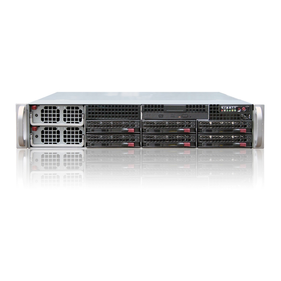
- Page 3 Preface Preface About This Manual This manual is written for professional system integrators and PC technicians. It provides information for the installation and use of the SC828 chassis. Installation and maintenance should be performed by experienced technicians only. Supermicro’s SC828 chassis features a unique and highly-optimized design. The chassis is equipped with a front-loading 1000W or 1200W high-efficiency redundant power supply.
- Page 4 SC828 Chassis Manual Manual Organization Chapter 1 Introduction The first chapter provides a checklist of the main components included with this SC828 chassis and describes the main features of the chassis. This chapter also includes contact information. Chapter 2 System Safety This chapter lists warnings, precautions, and system safety.
-
Page 5: Table Of Contents
Preface Table of Contents Chapter 1 Introduction Overview ......................1-1 Shipping List ....................1-1 Part Numbers ....................1-1 Where to get Replacement Components ............1-2 Contacting SuperMicro ..................1-3 Returning Merchandise for Service ..............1-4 Chapter 2 System Safety Overview ......................2-1 Warnings and Precautions ................ - Page 6 Preparing for Setup ..................5-1 Choosing a Setup Location ................5-1 Rack Precautions .................... 5-2 General Server Precautions ................5-2 Rack Mounting Considerations ............... 5-3 Ambient Operating Temperature ..............5-3 Reduced Airflow ....................5-3 Mechanical Loading ..................5-3 Circuit Overloading ..................5-3 Reliable Ground ....................
-
Page 7: Chapter 1 Introduction
Chapter 1: Introduction Chapter 1 Introduction Overview SC828 Supermicro’s chassis features a unique and highly-optimized design. The chassis is equipped with a high-efficiency 1000W or 1200W redundant power supply. Shipping List Part Numbers For the latest shiping lists and part numbers for your particular chassis model please visit the Supermicro Web site at http://www.supermicro.com/ SC828TQ-R1200B Chassis Power... -
Page 8: Where To Get Replacement Components
SC828 Chassis Manual Where to get Replacement Components Though not frequently, you may need replacement parts for your system. To en- sure the highest level of professional service and technical support, we strongly recommend purchasing exclusively from our Supermicro Authorized Distributors / System Integrators / Resellers. -
Page 9: Contacting Supermicro
Chapter 1: Introduction Contacting SuperMicro Headquarters Address: Super Micro Computer, Inc. 980 Rock Ave. San Jose, CA 95131 U.S.A. Tel: +1 (408) 503-8000 Fax: +1 (408) 503-8008 Email: marketing@supermicro.com (General Information) support@supermicro.com (Technical Support) Web Site: www.supermicro.com Europe Address: Super Micro Computer B.V. Het Sterrenbeeld 28, 5215 ML 's-Hertogenbosch, The Netherlands Tel:... -
Page 10: Returning Merchandise For Service
SC828 Chassis Manual Returning Merchandise for Service A receipt or copy of your invoice marked with the date of purchase is required be- fore any warranty service will be rendered. You can obtain service by calling your vendor for a Returned Merchandise Authorization (RMA) number. When returning to the manufacturer, the RMA number should be prominently displayed on the outside of the shipping carton, and mailed prepaid or hand-carried. -
Page 11: Chapter 2 System Safety
Chapter 2: System Safety Chapter 2 System Safety Overview This chapter provides a quick setup checklist to get your chassis up and running. Following the steps in order given should enable you to have your chassis setup and operational within a minimal amount of time. This quick set up assumes that you are an experienced technician, famailiar with common concepts and terminology. -
Page 12: Electrical Safety Precautions
SC828 Chassis User's Manual Electrical Safety Precautions Basic electrical safety precautions should be followed to protect yourself from harm and the SC828 from damage: • Be aware of the locations of the power on/off switch on the chassis as well as the room’s emergency power-off switch, disconnection switch or electrical outlet. -
Page 13: General Safety Precautions
Chapter 2: System Safety • DVD-ROM Laser: CAUTION - This server may have come equipped with a DVD-ROM drive. To prevent direct exposure to the laser beam and hazardous radiation exposure, do not open the enclosure or use the unit in any uncon- ventional way. - Page 14 SC828 Chassis User's Manual • Touch a grounded metal object before removing any board from its antistatic bag. • Do not let components or PCBs come into contact with your clothing, which may retain a charge even if you are wearing a wrist strap. •...
-
Page 15: Chapter 3 Chassis Components
Chapter 3: Chassis Components Chapter 3 Chassis Components Overview This chapter describes the most common components included with your chassis. Some components listed may not be included or compatible with your particular chassis model. For more information, see the installation instructions detailed later in this manual. -
Page 16: Mounting To A Rack (Optional)
SC828 Chassis Manual Mounting to a Rack (optional) SC828 can be placed in a rack for secure storage and use. To setup your rack, follow the step-by-step instructions included in this manual. Power Supply SC828 Each chassis model includes a high-efficiency power supply with thermal control fan, rated at 1000 or 1200 Watts. - Page 17 Chapter 3: Chassis Components Control Panel Buttons There are two push-buttons located on the front of the chassis. These are (in order from left to right) a reset button and a power on/off button. Reset: The reset button is used to reboot the system. ...
- Page 18 SC828 Chassis Manual Overheat/Fan Fail: When this LED flashes it indicates a fan failure. When continuously on (not flashing) it indicates an overheat condition, which may be caused by cables obstructing the airflow in the system or the ambient room tem- perature being too warm.
-
Page 19: Chapter 4 Chassis Setup And Installation
Chapter 3: Installation Procedures Chapter 4 Chassis Setup and Installation Removing the Chassis Cover Before installing any components, replacing chassis fans or accessing the mother- board, you will first need to remove the top cove from the chassis. Removing the Chassis Cover Unplug the power cord from the chassis. - Page 20 SC828 Chassis User's Guide Figure 4-2 Lifting the Chassis Cover...
-
Page 21: Installing The Motherboard Into The Chassis
Chapter 3: Installation Procedures Installing the Motherboard into the Chassis Installing the Motherboard Ensure that the power cord has been unplugged from the chassis. Locate the mounting holes on the motherboard and the mounting holes on the chassis. Align the mounting holes on the motherboard against the corresponding mounting holes on the chassis. -
Page 22: Removing And Installing Chassis Fans
SC828 Chassis User's Guide Removing and Installing Chassis Fans The SC828 chassis comes equipped with six 6500 RPM fans for optimal cooling. In the unlikely event that a fan needs to be replaced, removing and installing chassis fans is a simple procedure. Removing a Chassis Fan If necessary, open the chassis while the power is running to determine which fan has failed. - Page 23 Chapter 3: Installation Procedures Installing a Chassis Fan Turn off the power to the system and unplug the system from the outlet. Slide the fan housing into the chassis fan mounting bracket. Push down gently on the top of the fan until it clicks into place Reconnect the fan wiring to the connectors.
-
Page 24: Power Supply
SC828 Chassis User's Guide Power Supply The SC828 chassis has a 1000 or 1200 Watt power supply. This power supply is auto-switching capable. This enables it to automatically sense and operate at a 100v to 240v input voltage. The SC828 chassis has two power supplies. In the unlikely event that a power supply unit fails, the system will shut down and you will need to change the power supply unit. - Page 25 Chapter 3: Installation Procedures On the front of the chassis, press the release button on the front face of the power supply. Lift the handle upwards Gently pull the power supply forward and out of the chassis. Ensure that all screws are set aside for later use when installing the replace- ment power supply.
-
Page 26: Installing The Power Supply
SC828 Chassis User's Guide Installing the Power Supply Power Supply Installation Unplug all power leading to the chassis. Using the screws previously set aside, secure the power distributor to the floor of the chassis. Figure 4-9 Replacing the Power Distributor and Power Cord Channel Reattach the power cord channel to the power distributor Connect the power cord to the power supply and run the cord through the power cord channel and out of the chassis. - Page 27 Chapter 3: Installation Procedures Replace the power cord channel cover on the power cord channel. Insert the power supply into its slot in the front of the chassis, gently pushing it back into the chassis until it clicks into position. Figure 4-11 Replacing the Power Cord Channel Cover...
-
Page 28: Installing The Air Shroud
SC828 Chassis User's Guide Installing the Air Shroud The air shroud is used to channel the air flow from the system fans and direct it into critical areas of the chassis that require cooling. The SC828 chassis comes equipped with an adjustable air shroud, which allows the direction of the airflow to be fine-tuned for optimal cooling. -
Page 29: Removing The Hard Drive Tray And Installing A Hard Drive
Chapter 3: Installation Procedures Removing the Hard Drive Tray and Installing a Hard Drive To install a hard disk drive into the chassis, it is necessary to remove the HDD tray from the chassis. Removing a Hard Drive Tray Press the release tab on the front of each hard drive try to unlock the HDD tray. - Page 30 SC828 Chassis User's Guide Replacing a Hard Drive in the Hard Drive Tray Remove the two screws that attach to the both sides of the dummy HDD. Slide out the dummy HDD as shown Figure 4-8 Removing the Dummy Hard Drive Slide a hard drive into the HDD tray, and secure the HDD to the tray with two screws on each side of the tray as shown.
- Page 31 Chapter 3: Installation Procedures Installing a Hard Drive and Hard Drive Tray into the Chassis Insert the hard drive and hard drive tray into the hard drive tray slot in the chassis. Fold the HDD tray's handle inward until it clicks into the locked position. 4-13...
-
Page 32: Add-On Card/Expansion Slot Setup
SC828 Chassis User's Guide Add-on Card/Expansion Slot Setup L-Brackets Add-on/Expansion Card Add-on/Expansion Card Slots Figure 5-11: Remove the Add-on Card Slot screw SC828 chassis includes seven slots for add-on cards and expansion cards. Installing an Add-on or Expansion card: Confirm that each add on card you are installing includes a standard L- bracket. -
Page 33: Chapter 5 Rack Installation
Chapter 5 Rack Installation Chapter 5 Rack Installation Overview This chapter provides a quick setup checklist to get your chassis up and running. Following these steps in the order given should enable you to have the system operational within a minimum amount of time. Unpacking the System You should inspect the box the chassis was shipped in and note if it was damaged in any way. -
Page 34: Rack Precautions
SC828 Chassis Manual Warnings and Precautions! • This product is for installation only in a Restricted Access Location (dedicated equipment rooms, service closets and the like). Rack Precautions • Ensure that the leveling jacks on the bottom of the rack are fully extended to the floor with the full weight of the rack resting on them. -
Page 35: Rack Mounting Considerations
Chapter 5 Rack Installation • Always keep the rack's front door and all panels and components on the servers closed when not servicing to maintain proper cooling. Rack Mounting Considerations Ambient Operating Temperature If installed in a closed or multi-unit rack assembly, the ambient operating tempera- ture of the rack environment may be greater than the ambient temperature of the room. -
Page 36: Rack Mounting Instructions
SC828 Chassis Manual Rack Mounting Instructions This section provides information on installing the SC828 chassis into a rack unit with the rails provided. There are a variety of rack units on the market, which may mean the assembly procedure will differ slightly. You should also refer to the instal- lation instructions that came with the rack unit you are using. - Page 37 Chapter 5 Rack Installation Replacing the Inner Rails: Power down and unplug the chassis. It is also recommended that you remove the power plug from the chassis. On a solid, stable surface, lay the chassis on its side. The inner rail is held in place by one screw near the rear of the chassis. Remove this screw.
-
Page 38: Outer Rack Rails
SC828 Chassis Manual Secure to the Front of the Rack Secure to the Rear of the Rack Attach Outer Racks together Figure 5-2 Assembling the Outer Rails Outer Rack Rails Outer rails attach to the server rack and hold the server in place. The outer rails for the SC828 chassis extend between 26"... - Page 39 Chapter 5 Rack Installation Figure 5-3: Installing the Rack Rails Installing the Chassis into a Rack: Confirm that chassis includes the inner rails and rail extensions. Also, confirm that the outer rails are installed on the rack. Line chassis rails with the front of the rack rails. Slide the chassis rails into the rack rails, keeping the pressure even on both sides (you may have to depress the locking tabs when inserting).
-
Page 40: Appendix A Cables, Screws, And Other Accessories
Appendix A: Chassis Cables Appendix A Cables, Screws, and other Accessories A-1 Overview This appendix lists supported cables for your chassis system. It only includes the most commonly used components and configurations. For more compatible cables, refer to the manufacturer of the motherboard you are using and our Web site at: www.supermicro.com. - Page 41 SC502 Chassis Manual A-3 Chassis Screws The accessory box includes all the screws needed to setup your chassis. This section lists and describes the most common screws used. Your chassis may not require all the parts listed. HARD DRIVE Flat head Pan head 6-32 x 5 mm 6-32 x 5 mm...
-
Page 42: Appendix B Power Supply Specifications
Appendix B: Power Supply Specifications Appendix B Power Supply Specifications This appendix lists power supply specifications for your chassis system. SC828TQ-R1200LPB 1200W MFR Part # PWS-IK22-1R 100 - 240V Rated AC Voltage 50 - 60Hz 6-15Amp +5V standby 4 Amp +12V 100 Amp +5V 30 Amp +3.3V 25 Amp... - Page 43 SC502 Chassis Manual Notes...
-
Page 44: Appendix Cbpn-Sas-828Tq Backplane Specifications
Safety Information and Technical Specifications Appendix C BPN-SAS-828TQ Backplane Specifications To avoid personal injury and property damage, carefully follow all the safety steps listed below when accessing your system or handling the components. C-1 ESD Safety Guidelines Electric Static Discharge (ESD) can damage electronic components. To prevent dam- age to your system, it is important to handle it very carefully. - Page 45 Appendix C Backplane Specifications Jumper Settings and Pin Definitions C-4 Front Connectors and Jumpers SIDEBAND#2 ACT5 JP45 ACT IN JP43 ACT4 BAR CODE JP37 JP41 JP38 I C#2 JP26 UPGRADE JP34:BP_ID#1 JP37:BP_ID#2 JP13 1-2:ID#0 JP50:I2CRST#1 2-3:ID#1 JP38:I2CRST#2 OFF:SGPIO ON:I2C I C#1 +12V JP40 JP18:BUZZER RESET...
- Page 46 Safety Information and Technical Specifications C-5 Front Connector and Pin Definitions 1. CD-ROM/Floppy 4-Pin Connectors CD-ROM/ FDD Power The 4-pin connectors, designated JP105 and 4-Pin Connector (JP17 and JP18) JP106, provide power to the CD-ROM and Pin# Definition floppy drives. See the table on the right for pin definitions.
- Page 47 Appendix C Backplane Specifications 7. MG9072 Chip The MG9072 is an enclosure management chip that supports the SES-2 controller and SES-2 protocols. 8. Activity LED Header SAS Activity LED Header Pin Definitions (JP26) The activity LED header, designated JP26, Pin # Definition Pin # Definition...
- Page 48 Safety Information and Technical Specifications C-6 Front Jumper Locations and Pin Definitions JP41 JP38 JP43 SIDEBAND#2 JP45 JP43 JP37 JP37 JP38 SIDEBAND#2 JP41 JP45 JP36 JP43 I C#2 JP37 BAR CODE UPGRADE I C#2 JP34:BP_ID#1 JP50 UPGRADE JP37:BP_ID#2 JP50:I2CRST#1 1-2:ID#0 JP34 JP38:I2CRST#2 2-3:ID#1...
- Page 49 Appendix C Backplane Specifications C and SGPIO Modes and Jumper Settings This backplane can utilize I C or SGPIO. SGPIO is the default mode and can be used without making changes to your jumpers. The following information details which jumpers must be configured to use I C mode or restore your backplane to SGPIO mode.
- Page 50 Safety Information and Technical Specifications C-7 Rear Connectors and LED Indicators SAS #3 SAS #5 SAS #4 SAS#3 SAS#4 SAS#5 SAS #2 SAS #0 SAS #1 SAS#0 SAS#1 SAS#2 Rear SAS/SATA Connectors Rear SAS Drive Connector Number SAS #0 SAS/SATA HDD #0 SAS #1 SAS/SATA HDD #1 SAS #2...
Need help?
Do you have a question about the SC828 Series and is the answer not in the manual?
Questions and answers