Supero SC836TQ-R800V User Manual
Hide thumbs
Also See for SC836TQ-R800V:
- User manual (110 pages) ,
- User manual (122 pages) ,
- User manual (117 pages)

Related Manuals for Supero SC836TQ-R800V


Summary of Contents for Supero SC836TQ-R800V
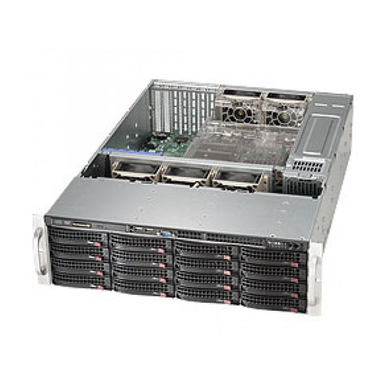
- Page 1 UPER SC836 CHASSIS Series SC836TQ - R800V(B) SC836E1 - R800V(B) SC836E2 - R800V(B) USER’S MANUAL 1.0d...
- Page 2 SC836 Chassis Manual The information in this User’s Manual has been carefully reviewed and is believed to be accurate. The vendor assumes no responsibility for any inaccuracies that may be contained in this document, makes no commitment to update or to keep current the information in this manual, or to notify any Please Note: For the most up-to-date version of person or organization of the updates.
- Page 3 Preface Preface About This Manual This manual is written for professional system integrators and PC technicians. It provides information for the installation and use of the SC836 3U chassis. Installa- tion and maintenance should be performed by experienced technicians only. Supermicro’s SC836 3U chassis features a unique and highly-optimized design for dual-core Xeon platforms.
- Page 4 SC836 Chassis Manual Notes...
-
Page 5: Preface
Preface Manual Organization Chapter 1: Introduction The fi rst chapter provides a checklist of the main components included with this chassis and describes the main features of the SC836 chassis. This chapter also includes contact information. Chapter 2: System Safety This chapter lists warnings, precautions, and system safety. - Page 6 SC836 Chassis Manual Compatible Backplanes This section lists compatible cables, power supply specifications, and compatible backplanes. Not all compatible backplanes are listed. Refer to our Web site for the latest compatible backplane information. Appendix A: SC836 Chassis Cables Appendix B: SC836 Power Supply Specifi cations Appendix C: SAS 836EL Series Backplane Manual Appendix D: SAS 836TQ Backplane Manual Appendix E: Power Control Card: CSE-PTJBOD-CB1...
-
Page 7: Table Of Contents
Preface Table of Contents Preface About This Manual ...................... iii Manual Organization ....................v Table of Contents ....................... vii Chapter 1: Introduction Overview ......................1-1 Shipping List ....................1-1 Chassis Features .................... 1-2 Contacting Supermicro ................... 1-3 Chapter 2: System Safety Overview ...................... - Page 8 SC836 Chassis Manual To install a hard drive to the hard drive tray .......... 5-3 Installation Step 3: Installing the Motherboard ..........5-5 Permanent and Optional Standoffs ............5-5 Stand Off Labeling ................... 5-5 To install the motherboard ............... 5-5 Power Supply Connections ..............
- Page 9 Preface Chapter 7: Rack Installation Overview ......................7-1 Unpacking the System ................... 7-1 Preparing for Setup ..................7-1 Choosing a Setup Location ..............7-1 Rack Precautions ..................7-2 General Server Precautions ..............7-2 Rack Mounting Considerations ..............7-2 Rack Mounting Instructions ................7-4 To install the rack rails ................
- Page 10 SC836 Chassis Manual Notes...
-
Page 11: Chapter 1: Introduction
SC836 Chassis Series Power Model I/O Slots Supply DP Dual- 16x SAS / 7x FF R800W SC836TQ-R800V(B) core Xeon SATA DP Dual- 16x SAS 7x FF R800W SC836E1-R800V(B) core Xeon DP Dual- 16x SAS 7x FF... -
Page 12: 1-3 Chassis Features
SC836 Chassis Manual 1-3 Chassis Features The SC836 3U high performance chassis includes the following features: CPU Support The SC836 Chassis supports a DP Dual-core Xeon processor. Please refer to the motherboard specifications pages on our Web site for updates on supported processors for this chassis Hard Drives The SC836 Chassis features 16 slots for U320 SCSI or SAS/SATA drives. -
Page 13: Contacting Supermicro
Chapter 1: Introduction Contacting SuperMicro Headquarters Address: SuperMicro Computer, Inc. 980 Rock Ave. San Jose, CA 95131 U.S.A. Tel: +1 (408) 503-8000 Fax: +1 (408) 503-8008 Email: marketing@supermicro.com (General Information) support@supermicro.com (Technical Support) Web Site: www.supermicro.com Europe Address: SuperMicro Computer B.V. Het Sterrenbeeld 28, 5215 ML 's-Hertogenbosch, The Netherlands Tel:... - Page 14 SC836 Chassis Manual Notes...
-
Page 15: Chapter 2: System Safety
Chapter 2: System Safety Chapter 2 System Safety Overview This chapter provides a quick setup checklist to get your chassis up and running. Following the steps in order given should enable you to have your chassis setup and operational within a minimal amount of time. These instructions assume that you are an experienced technician, familiar with common concepts and terminology. -
Page 16: General Safety Precautions
SC836 Chassis Manual cal outlet. If an electrical accident occurs, you can then quickly remove power from the system. Do not work alone when working with high voltage components. Power should always be disconnected from the system when removing or installing main system components, such as the serverboard, memory mod- ules and the DVD-ROM and floppy drives (not necessary for hot swappable drives). -
Page 17: System Safety
Chapter 2: System Safety Place the chassis top cover and any system components that have been removed away from the system or on a table so that they won’t accidentally be stepped on. While working on the system, do not wear loose clothing such as neckties and unbuttoned shirt sleeves, which can come into contact with electrical circuits or be pulled into a cooling fan. - Page 18 SC836 Chassis Manual When handling chips or modules, avoid touching their pins. Put the serverboard and peripherals back into their antistatic bags when not in use. For grounding purposes, make sure your computer chassis provides excel- lent conductivity between the power supply, the case, the mounting fasten- ers and the serverboard.
-
Page 19: Chapter 3: Chassis Components
Chapter 3: Chassis Components Chapter 3 Chassis Components Overview This chapter describes the most common components included with your chassis. Some components listed may not be included or compatible with your particular chassis model. For more information, see the installation instructions detailed later in this manual. - Page 20 SC836 Chassis Manual Power Supply Each SC836 chassis model includes redundant high-efficiency "hot-swappable" power supply rated at 800 Watts. In the unlikely event power supply fails in one power supply, you can remove and replace the faulty power supply without power- ing down the system.
-
Page 21: Chapter 4: System Interface
Chapter 4: System Interface Chapter 4 System Interface Overview There are several LEDs on the control panel as well as others on the drive carriers to keep you constantly informed of the overall status of the system as well as the activity and health of specific components. -
Page 22: Control Panel
SC836 Chassis Manual Control Panel Buttons There are two push-buttons located on the front of the chassis. These are (in order from left to right) a reset button and a power on/off button. Reset: The reset button is used to reboot the system. Power: The main power switch is used to apply or remove power from the power supply to the server system. - Page 23 Chapter 4: System Interface Overheat/Fan Fail: When this LED flashes it indicates a fan failure. When continuously on (not flashing) it indicates an overheat condition, which may be caused by cables obstructing the airflow in the system or the ambient room tem- perature being too warm.
-
Page 24: Drive Carrier Leds
SC836 Chassis Manual Drive Carrier LEDs Each SAS drive carrier has two LEDs. Blue: When illuminated, this blue LED (on the front of the drive carrier) indicates drive activity. A connection to the SAS backplane enables this LED to blink on and off when that particular drive is being accessed. Red: The red LED to indicate a drive failure. -
Page 25: Chapter 5: Chassis Setup
Chapter 5: Chassis Setup Chapter 5 Basic Chassis Setup and Maintenance Overview This chapter details the basic steps required to install components to the chassis. The only tool you will is a Phillips screwdriver. Print this page to use as a reference while setting up your chassis. - Page 26 SC836 Chassis Manual Installation Step 1: Remove the Chassis Cover Release Tab Remove this screw (if necessary) Figure 5-1: Removing the Chassis Cover To remove the chassis cover: 1. Press the release tabs to remove the cover from the locked position. Press both tabs at the same time.
-
Page 27: Installation Step 2: Install Hard Drives
Chapter 5: Chassis Setup Installation Step 2: Install Hard Drives The drives are mounted in drive trays to simplify their installation and removal from the chassis. To remove hard drive trays from the chassis 1. Press the release button on the drive tray. This extends the drive bay handle. 2. - Page 28 SC836 Chassis Manual SAS/SATA or SCSI Hard Drive Hard Drive Tray Use a Hard, Stable Surface when installing the Hard Drive Figure 5-3: Install SAS or SATA Drive to Hard Drive Tray 2. Place the hard drive tray on a flat, stable surface such as a desk, table, or work bench.
-
Page 29: Installation Step 3: Installing The Motherboard
Chapter 5: Chassis Setup Installation Step 3: Installing the Motherboard Permanent and Optional Standoffs Standoffs prevent short circuits by securing space between the motherboard and the chassis surface. The SC836 chassis includes permanent standoffs in locations used by most motherboards. These standoffs accept the rounded Phillips head screws included in the SC836 accessories packaging. - Page 30 SC836 Chassis Manual 4. Remove any packaging from the chassis. If the rear fans (set of two fans nearest the I/O slots) or the air shroud is in place, remove them. 5. If required by your motherboard, install standoffs in any areas that do not have a permanent standoff.
-
Page 31: Power Supply Connections
Chapter 5: Chassis Setup Power Supply Connections Connect each of the following cables, as required, by your motherboard manufac- turer. In some instances, some cables may not need to be connected. Power Supply Cable Num- Connects Name Description 20-pin or 24-pin power cable provides 20-pin or 24-pin mother- electricity to the motherboard. -
Page 32: To Install The Add On Or Expansion Card
SC836 Chassis Manual I/O Shield and Add On Card Setup The SC836 chassis includes space for an I/O shield and up to seven Add On/Ex- pansion cards. Figure 5-4: SC836 Chassis Rear Add On/Expansion with seven full length/full height I/O Port panel Card Slots Add On Card slots and I/O ports To install an Add On or Expansion Card... - Page 33 Chapter 5: Chassis Setup To install an I/O port panel 1. Remove the chassis cover. 2. Locate the I/O port panel. 3. Depending on your motherboard, you must remove the existing port shield and replace with the new one or use the existing the shield to slide the ports through. 4.
-
Page 34: To Install The Air Shroud
SC836 Chassis Manual Installation Step 4: Installing the Air Shroud, Rear Fan, and Checking Air Flow Figure 5-6: Place the Air Shroud Air shrouds concentrate airflow to maximize fan efficiency. The SC836 chassis air shroud does not require screws to set up. To install the air shroud 1. -
Page 35: Rear System Fans
Chapter 5: Chassis Setup Rear System Fans The SC836 Chassis includes three front fans and two rear fans. The front fans are pre-installed. The rear fans must be installed after motherboard and air shroud setup. Figure 5-7: Install the Rear Fan Installing the rear system fans 1. -
Page 36: To Check The Server's Air Flow
SC836 Chassis Manual To check the server's air fl ow 1. Make sure there are no objects to obstruct airflow in and out of the server. If necessary, route the cables through the cable rack. 2. Do not operate the server without drives or drive trays in the drive bays. 3. -
Page 37: Chassis Maintenance
Chapter 5: Chassis Setup Chassis Maintenance System Fans Five heavy duty fans provide cooling for the chassis. These fans circulate air through the chassis as a means of lowering the chassis' internal temperature. The SC836 Chassis includes three front fans and two rear fans. SC 836 chassis fans are fully hotswappable. -
Page 38: Power Supply
SC836 Chassis Manual Power Supply The power supply for the SC 836 Chassis is redundant and hot swappable, meaning the power supply can be changed without powering down the system. Replacing the Power Supply 1. The SC836 chassis includes a redundant power supply (at least two power modules), you can leave the server running if you remove only one power sup- ply at a time. -
Page 39: Replacing The Power Distributor
Chapter 5: Chassis Setup Replacing the Power Distributor Redundant server chassis that are 2U or more high require a power distributor. The power distributor provides failover and power supply redundancy. In the unlikely event you must replace the power distributor, do following 1. -
Page 40: Replacing The Dvd-Rom, Floppy Drive, And Front Panel
SC836 Chassis Manual Replacing the DVD-ROM, Front Panel, and Floppy Drive SC836 chassis models include a slim DVD-ROM, slim Floppy Drive, and Front Port Panel. Use the instructions in this section in the unlikely event that you must replace any of these components. The DVD-ROM goes into the right slot. -
Page 41: To Replace Or Install The Dvd Drive
Chapter 5: Chassis Setup To replace or install the DVD drive 1. Power down and unplug the system 2. Remove the chassis cover. 3. (If you are not installing a new front port panel) Remove the mini-bezel (grate) from the drive bay The mini-bezel is the small grating that covers the drive bay. Remove this by simply pulling it out of the bay. - Page 42 SC836 Chassis Manual To replace or install the Front Port Panel 1. Power down and unplug the system 2. Remove the chassis cover. 3. (If you are not installing a new front port panel) Remove the mini-bezel (grate) from the drive bay The mini-bezel is the small grating that covers the drive bay. Remove this by simply pulling it out of the bay.
-
Page 43: Chapter 6: Advanced Setup
Chapter 6: Chassis Setup and Maintenance Chapter 6 Advanced Setup Overview This chapter covers the steps required to take advantage of the dual port, failover, and cascading features available with the 836EL series backplanes. If you are not using an 836EL series backplane or you do not want to take advantage of the advanced features, you can skip this chapter Specific examples and cascading instructions can be found in the SC836 Backplane Manual located in the Appendix section. -
Page 44: Dual And Expanders
SC836 Chassis Manual Dual Port and Expanders Single Ports SC 836EL1 backplanes have a single-port expander that access all 16 drives and supports cascading. Dual Ports SC 836EL2 backplanes have dual-port expanders that access all 16 drives. These dual-port expanders supports cascading, failover and recovery. Note: Both 836EL series backplanes support SAS drives only. -
Page 45: Failover
Chapter 6: Chassis Setup and Maintenance Failover Failover is the ability to automatically switch to a redundant path when a primary path fails or becomes unavailable. Failover is automatic and requires no action on the part of the Administrator. The SC 836EL2 backplane has two expanders which allow effective failover and recovery. -
Page 46: Dual Host Bus Adapter
SC836 Chassis Manual Dual Host Bus Adapter SAS HBA In a Dual Host Bus Configuration, the SAS HBA backplane connects to two Host Bus Adapters (HBA). PRI_J2 SEC_J2 PRI_J1 SEC_J0 SEC_J1 PRI_J0 Port B Port A Expander 2 Expander 1 Dual Host Bus Adapter Failover SAS HBA If the Expander or data path in Port A... -
Page 47: Chapter 7: Rack Installation
Chapter 7: Rack Installation Chapter 7 Rack Installation Overview This chapter provides a quick setup checklist to get your chassis up and running. Following these steps in the order given should enable you to have the system operational within a minimum amount of time. Unpacking the System You should inspect the box the chassis was shipped in and note if it was damaged in any way. -
Page 48: Rack Precautions
SC836 Chassis Manual Warnings and Precautions! Rack Precautions - Ensure that the leveling jacks on the bottom of the rack are fully extended to the floor with the full weight of the rack resting on them. - In single rack installation, stabilizers should be attached to the rack. - In multiple rack installations, the racks should be coupled together. - Page 49 Chapter 7: Rack Installation Reduced Airfl ow Equipment should be mounted into a rack so that the amount of airflow required for safe operation is not compromised. Mechanical Loading Equipment should be mounted into a rack so that a hazardous condition does not arise due to uneven mechanical loading.
-
Page 50: Rack Mounting Instructions
SC836 Chassis Manual Rack Mounting Instructions This section provides information on installing the SC836 chassis into a rack unit with the rails provided. There are a variety of rack units on the market, which may mean the assembly procedure will differ slightly. You should also refer to the installation instructions that came with the rack unit you are using. -
Page 51: To Install The Rack Rails
Chapter 7: Rack Installation Locking Tabs Figure 7-2: Installing the Inner Rack Rails To install the rack rails 1. Place the inner rack extensions on the side of the chassis aligning the hooks of the chassis with the rail extension holes. 2. -
Page 52: Outer Rack Rails
SC836 Chassis Manual Figure 7-3: Installing the Chassis into the Server Rack Outer Rack Rails Outer rails attach to the server rack and hold the server in place. The outer rails for the SC836 chassis extend between 30 inches and 33 inches. To install the Outer Rack Rails 1. -
Page 53: Installing The Chassis Into A Rack
Chapter 7: Rack Installation Figure 7-4: Installing the Chassis into the Server Rack Installing the chassis into a rack 1. Confi rm that the inner and outer rails are installed on the rack. 2. Line chassis rails with the front of the rack rails. 3. - Page 54 SC836 Chassis Manual Notes...
-
Page 55: Appendices
Appendices Appendices Appendix A: Compatible Cables Appendix B: SC836 Power Supply Specifi cations Appendix C: SAS 836EL Series Backplane Manual Appendix D: SAS 836TQ Backplane Manual Appendix E: Power Card: CSE-PTJOBD-CB1... - Page 56 Appendices Notes...
-
Page 57: Appendix A: Sc836 Chassis Cables
Appendix A Appendix A SC836 Chassis Cables Overview This appendix lists supported cables for your chassis system. It only includes the most commonly used components and configurations. For more compatible cables, refer to the manufacturer of the motherboard you are using and our Web site at: www.supermicro.com. - Page 58 SC836 Chassis Manual Cables Included with SC836E Chassis SC836E-800 Part # Type Length Description CBL-0078 Cable 45cm Round Floppy Drive Cable Ribbon, 16 pin to 16 pin ribbon cable for CBL-0087 20" Round control panel CBL-0139L Wire 50 cm IDE 80-Wire cable for DVD ROM Cable Regional power cord...
- Page 59 Appendix A Compatible Cables Alternate SAS Cables Some compatible motherboards have different connectors. If your motherboard has only one SAS connector that the SAS cables must share, use one of the following cables. These cables must be purchased separately. Cable Name: SAS Cable Quantity: 1 Part #: CBL-0175L Alt.
- Page 60 SC836 Chassis Manual Cascading/JBOD SAS Cables Use the following cables when setting up a cascading or JBOD system. Cable Name: SAS Cable Quantity: varies by setup Part #: CBL-0167L Placement: Internal cable Ports: Single Description: Internal cable. Connects the backplane to the Host Bus Adapter (HBA) or external port.
- Page 61 Appendix A Cable Name: SAS Cable Quantity: varies by setup Part #: CBL-0166L Placement: External cable Ports: Single or Dual Description: External cascading cable. Connects ports between servers. With most connectors, use one cable for single port connections and two cables for dual port connections.
- Page 62 SC836 Chassis Manual Extending Power Cables Although Super Micro chassis are designed with to be efficient and cost-effective, some compatible motherboards have power connectors located in different areas. To use these motherboards you may have to extend the power cables to the mother boards.
-
Page 63: Appendix B: Sc836 Power Supply Specifications
Appendix B Appendix B SC836 Power Supply Specifi cations This appendix lists power supply specifications for your chassis system. 800W (Redundant) MFR Part # PWS-801-1R 100 - 240V Rated AC Voltage 50 - 60Hz 10A - 4 Amp +5V standby 4 Amp +12V 66 Amp +5V 25 Amp +3.3V 12 Amp... - Page 64 SC836 Chassis Manual Notes...
-
Page 65: Appendix C: Sas 836El Series Backplane
PRI_J2 SEC_J2 PRI_J1 OVERHEATFAIL1 FANFAIL1 5V_LED 12V_LED BUZZER_ENB1 JP106 SEC_J0 SEC_J1 PRI_J0 JP105 BUZZER1 SEC_EXP PWR1 PWR0 PRI_EXP +12V +12V SAS836EL REV 1.01 PWR3 PWR2 +12V +12V FAN1 FAN3 FAN2 FAN4 SAS 836EL SERIES BACKPLANE USER'S GUIDE Rev. 1.0e... - Page 66 Backplane User's Guide The information in this User’s Manual has been carefully reviewed and is believed to be accurate. The vendor assumes no responsibility for any inaccuracies that may be contained in this document, makes no commitment to update or to keep current the information in this manual, or to notify any Please Note: For the most up-to-date version of person or organization of the updates.
- Page 67 Safety Information and Technical Specifications Table of Contents SAS 836EL SERIES BACKPLANE Contacting SuperMicro ....................iv Chapter 1: Safety Guidelines ESD Safety Guidelines ................... 1-1 General Safety Guidelines ................1-1 An Important Note to Users ................1-1 Chapter 2: Jumper Settings and Pin Defi nitions 2-1 Front Connectors and Jumpers ................
-
Page 68: Contacting Supermicro
Backplane User's Guide Contacting SuperMicro Headquarters Address: SuperMicro Computer, Inc. 980 Rock Ave. San Jose, CA 95131 U.S.A. Tel: +1 (408) 503-8000 Fax: +1 (408) 503-8008 Email: marketing@supermicro.com (General Information) support@supermicro.com (Technical Support) Web Site: www.supermicro.com Europe Address: SuperMicro Computer B.V. Het Sterrenbeeld 28, 5215 ML 's-Hertogenbosch, The Netherlands Tel:... -
Page 69: Chapter 1: Safety Guidelines
Safety Information and Technical Specifications Chapter 1: Safety Guidelines To avoid personal injury and property damage, carefully follow all the safety steps listed below when accessing your system or handling the components. ESD Safety Guidelines Electric Static Discharge (ESD) can damage electronic com ponents. To prevent dam- age to your system, it is important to handle it very carefully. - Page 70 Backplane User's Guide Notes...
-
Page 71: Chapter 2: Jumper Settings And Pin Defi Nitions
Safety Information and Technical Specifications Chapter 2: Jumper Settings and Pin Defi nitions 2-1 Front Connectors and Jumpers PRI_J2 SEC_J2 PRI_J1 5V_LED 12V_LED BUZZER_ENB1 SEC_J0 SEC_J1 OVERHEATFAIL1 FANFAIL1 JP106 PRI_J0 JP105 BUZZER1 SEC_EXP PWR1 PWR0 PRI_EXP +12V +12V SAS836EL REV 1.01 PWR3 PWR2 +12V... -
Page 72: Front Connector And Pin Definitions
Backplane User's Guide Front Connector and Pin Defi nitions #1. CD-ROM/Floppy 4-Pin Connectors CD-ROM/ FDD Power The 4-pin connectors, designated JP105 4-Pin Connector (JP105 and JP106) and JP106, provide power to the CD-ROM Pin# Definition and floppy drives. See the table on the right for pin definitions. - Page 73 Safety Information and Technical Specifications #6. Primary and Secondary Flash Chips The Primary and Secondary Flash Chips enhance the backplane memory. #7. EPP Ports The EPP ports are used for manufacturer diagnostic purposes only. #8. Fan Connectors Fan Connectors (Fan1, Fan2, Fan3, The 3-pin connectors, designated Fan2, and Fan4) Fan3, and Fan4, provide power to the...
- Page 74 Backplane User's Guide Notes...
-
Page 75: Front Jumper Locations And Pin Definitions
Safety Information and Technical Specifications Front Jumper Locations and Pin Defi nitions PRI_J2 SEC_J2 PRI_J1 OVERHEATFAIL1 FANFAIL1 5V_LED 12V_LED BUZZER_ENB1 JP106 SEC_J0 SEC_J1 PRI_J0 JP105 BUZZER1 SEC_EXP PWR1 PWR0 PRI_EXP +12V +12V SAS836EL REV 1.01 PWR3 PWR2 +12V +12V FAN1 FAN3 FAN2 12V_LED... - Page 76 Backplane User's Guide Socket Settings Socket Socket Setting Note REMOTE_FAN_FAIL_ Front Panel Fan Fail indicator Connected SOCKET (Optional)
- Page 77 Safety Information and Technical Specifications FRONT LED INDICATORS PRI_J2 SEC_J2 PRI_J1 OVERHEATFAIL1 FANFAIL1 5V_LED 12V_LED BUZZER_ENB1 JP106 SEC_J0 SEC_J1 PRI_J0 JP105 BUZZER1 SEC_EXP PWR1 PWR0 PRI_EXP +12V +12V SAS836EL REV 1.01 PWR3 PWR2 +12V +12V FAN1 FAN3 FAN2 FAN4 12V_LED 5V_LED OVERHEATFAIL1 FANFAIL1...
- Page 78 Backplane User's Guide Rear Connectors and LED Indicators ACT#3 ACT#7 ACT#11 ACT#15 FAIL#3 FAIL#7 FAIL#11 FAIL#15 SAS #3 SAS #7 SAS #11 SAS #15 ACT#2 ACT#10 ACT#6 ACT#14 FAIL#2 FAIL#10 FAIL#6 FAIL#14 SAS #2 SAS #6 SAS #10 SAS #14 ACT#1 ACT#9 ACT#13...
-
Page 79: Chapter 3: Dual Port And Cascading Confi Gurations
Safety Information and Technical Specifications hapter 3 Dual Port and Cascading Confi gurations Single and Dual Port Expanders Single Ports SC 836EL1 backplanes have a single-port expander that access all 16 drives and supports cascading. Dual Ports SC 836EL2 backplanes have dual-port expanders that access all 16 drives. These dual-port expanders support cascading, failover, and recovery. -
Page 80: Failover
Backplane User's Guide Failover The SC836EL2 Backplane has two expanders which allow effective failover and recovery. Single Host Bus Adapter SAS HBA In a single host bus configuration, the backplane connects to one Host Bus Adapter (HBA). PRI_J2 SEC_J2 PRI_J1 SEC_J0 SEC_J1 PRI_J0... -
Page 81: Cables And Chassis Power Card
Safety Information and Technical Specifications Cables and Chassis Power Card Chassis Power Card In a cascaded configuration, the fi rst chassis includes a motherboard and, at least one, Host Bus Adapter (HBA). Other servers in this enclosed system, include a power card. - Page 82 Backplane User's Guide Connecting an Internal Host Bus Adapter to the Backplane The following section lists the most common cables used to connect the HBA to the backplane. PRI_J2 SEC_J2 PRI_J1 SEC_J0 SEC_J1 PRI_J0 (Host Bus Adapter) Single Internal Host Bus Adapter SEC_J2 PRI_J2 PRI_J1...
- Page 83 Safety Information and Technical Specifications Cable Name: IPASS (mini SAS) TO IPASS (mini SAS) Part #: CBL-0108L-02 Length: 39 cm (15 inches) Part #: CBL-0109L-02 Length: 22 cm (9 inches) Part #: CBL-0110L-02 Length: 18 cm (7 inches) Description: This cable has an ipass (SFF-8087/mini-sas) connector (36 pins) at each end.
- Page 84 Backplane User's Guide Connecting an External Host Bus Adapter to the Backplane This backplane supports external Host Bus Adapters. In this configuration, the HBA and the backplane are in different physical chassis. This allows a JBOD (Just a Bunch Of Drives) configuration from an existing system. PRI_J2 SEC_J2 PRI_J1...
- Page 85 Safety Information and Technical Specifications Supported External HBA to Backplane Cable Use the following cable if your external HBA has an Infiniband connector. Cable Name: SAS InfiniBand to Mini SAS X4 1M cable, PBF Part #: CBL-0200L Length: 1 meter Description: This cable has an Infiniband connector (SFF-8470) on one end and an SFF-8088-1X (26-pins) at the other end.
- Page 86 Backplane User's Guide Connecting Multiple Backplanes in a Single Channel Environment This section describes the cables used when cascading from a single HBA. These connections use CBL-0167L internal cables and CBL-0166L external cables. Single HBA Conguration CBL-0167L with Single Port Assembly SEC_J2 PRI_J2 PRI_J1...
- Page 87 Safety Information and Technical Specifications Single HBA Confi guration Cables Single Port Cable Assembly Cable Name: SAS EL2/EL1 Backplane Cable (Internal) w/ 2-port Cascading Cable, 68 cm Part #: CBL-0167L (SFF-8087 to SFF-8088 x1) Ports: Single Placement: Internal cable Description: Internal cable. Connects the backplane to the Host Bus Adapter (HBA) or external port.
- Page 88 Backplane User's Guide Connecting Multiple Backplanes in a Dual Channel Environment This section describes the cables used when cascading from a single HBA. These connections use CBL-0168L internal cables and CBL-0166L external cables. PRI_J2 SEC_J2 PRI_J1 SEC_J0 SEC_J1 PRI_J0 Cable 0168L Port B Expander 2 Port A Expander 1 with Single Port Assembly...
- Page 89 Safety Information and Technical Specifications Dual HBA Conguration Cables Dual Port Cable Assembly Cable Name: SAS Dual-port Cable Assembly, 68/76cm Part #: CBL-0168L Placement: Internal cable Ports: Dual Description: Internal cascading cable. Connects the backplane to the Host Bus Adapter (HBA) or external port. Used in Dual port environments. Cable Name: SAS EL2/EL1 Cascading Cable (External), 68cm Part #: CBL-0166L Placement: External cable...
-
Page 90: Supported Cascading Configuration
Backplane User's Guide Supported Cascading Confi guration Cascading allows the system to access data at a faster rate by allowing several backplanes to share resources to reduce latency time. The fi rst backplane in a cascaded system requires a motherboard and HBA. Other servers require a power control card, not a motherboard and HBA. - Page 91 Safety Information and Technical Specifications Server System with Single SAS HBA The exanders allow horizontal branching. This configuration also applies to dual ports. PRI_J2 SEC_J2 PRI_J2 SEC_J2 PRI_J1 PRI_J1 SEC_J0 SEC_J1 SEC_J0 SEC_J1 PRI_J0 PRI_J0 Port A Expander 1 Port A Expander 1 Power Card Cable 0167L Single Port Cable...
- Page 92 Backplane User's Guide Server System with Dual SAS HBA and Cascading Confi guration SEC_J2 PRI_J2 PRI_J1 SEC_J0 SEC_J1 PRI_J0 Port A Expander 1 Port B Expander 2 (Host Bus Adapter) Dual Port Cable Assembly (Host Bus Adapter) Cable 0168L (internal cable) Cable 0166L SEC_J2 PRI_J2...
- Page 93 Safety Information and Technical Specifications Server System with Dual SAS HBA SEC_J2 PRI_J2 PRI_J1 SEC_J0 SEC_J1 PRI_J0 Port B Ex. 2 Port A Ex. 1 SEC_J2 PRI_J2 PRI_J1 SEC_J0 SEC_J1 PRI_J0 Port B Ex. 2 Port A Ex. 1 Power Card PRI_J2 SEC_J2...
- Page 94 Backplane User's Guide Dual Cable Routing External Cables In the previous diagrams external cables are represented with two different lines. These cables are both CBL-0166L CBL-0166L (external cable) External Cables. Different lines help the user determine cable routing. 3-16...
- Page 95 FAN#1 FAN#2 FAN#3 FAN#4 ALARM#1 ALARM#2 +12V FAIL BUZZER RESET FAIL FAIL FAIL UPGRADE#1 UPGRADE#2 JP101 JP102 JP90 JP91 JP18 JP100 I2C#4 I2C#1 JP87 I2C#2 JP96 I2C#3 JP37 JP95 JP52 JP99 JP77 JP65 JP66 JP75 SIDEBAND#1 SIDEBAND#4 JP98 SIDEBAND#2 SIDEBAND#3 JP97 ACT_IN#8-15 ACT_IN#0-7...
- Page 96 The information in this User’s Manual has been carefully reviewed and is believed to be accurate. The vendor assumes no responsibility for any inaccuracies that may be contained in this document, makes no commitment to update or to keep current the information in this manual, or to notify any Please Note: For the most up-to-date version of person or organization of the updates.
- Page 97 Safety Information and Technical Specifications Table of Contents Chapter 1: Safety Guidelines ESD Safety Guidelines ..................1-1 General Safety Guidelines ................1-1 An Important Note to Users ................1-1 Chapter 2: Jumper Settings and Pin Defi nitions Front Connectors and Jumpers ............... 2-1 Front Connector Pin Definitions ..............
- Page 98 SAS 836TQ Backplane User's Guide Notes...
-
Page 99: Chapter 1: Safety Guidelines
Safety Information and Technical Specifications Chapter 1 Safety Guidelines To avoid personal injury and property damage, carefully follow all the safety steps listed below when accessing your system or handling the components. ESD Safety Guidelines Electric Static Discharge (ESD) can damage electronic com ponents. To prevent dam- age to your system, it is important to handle it very carefully. - Page 100 SAS 836TQ Backplane User's Guide Notes...
-
Page 101: Front Connectors And Jumpers
Safety Information and Technical Specifications Chapter 2 Jumper Settings and Pin Defi nitions Front Connectors and Jumpers FAN#1 FAN#2 FAN#3 FAN#4 ALARM#1 ALARM#2 +12V BUZZER RESET FAIL FAIL FAIL FAIL UPGRADE#1 UPGRADE#2 JP101 JP102 JP91 JP90 JP18 JP100 I2C#4 I2C#1 JP87 JP96 I2C#2... - Page 102 SAS 836TQ Backplane User's Guide Front Connector and Pin Defi nitions #1. Activity LED Header SAS Activity LED Header Pin Defi nitions (JP26) The activity LED header, designated JP26 Pin # Definition Pin # Definition and JP47, is used to indicate the activity ACT IN#0 ACT IN#4 status of each SAS drive.
- Page 103 Safety Information and Technical Specifications #4. Fan Connectors Fan Connectors (JP54, JP56, JP58, The 3-pin connectors, designated JP54, and JP60) JP56, JP58 and JP60, provide power to Pin# Definition the fans. See the table on the right for pin Ground definitions.
- Page 104 SAS 836TQ Backplane User's Guide #14. Upgrade Connectors The upgrade connectors are designated JP69 and JP78. #15-#30. SAS Ports The SAS ports are used to connect the SAS drive cables. The 16 ports are designated #0 - #15. Each port is also compatible with SATA drives.
-
Page 105: Front Jumper Locations And Pin Definitions
Safety Information and Technical Specifications Front Jumper Locations and Pin Defi nitions JP90 JP91 JP84 JP85 FAN#1 FAN#2 FAN#3 ALARM#1 ALARM#2 +12V FAN#4 FAIL FAIL BUZZER RESET FAIL FAIL UPGRADE#1 JP104 JP102 JP103 JP101 UPGRADE#2 JP101 JP102 JP90 JP91 JP18 JP86 JP94 JP87... - Page 106 SAS 836TQ Backplane User's Guide Fan Jumper Settings This backplane can use up to four fans. To utilize each fan, you must configure both jumpers as instructed below. Fan Jumper Settings Jumper Jumper Settings Note Closed: With Fan FAN#1 JP61 Open: No Fan 1-2:With Fan FAN#1...
- Page 107 Safety Information and Technical Specifications C and SGPIO Modes and Jumper Settings This backplane can utilize I C or SGPIO. I C is the default mode and can be used without making changes to your jumpers. The following information details which jumpers must be configured to use SGPIO mode or restore your backplane to I mode.
- Page 108 SAS 836TQ Backplane User's Guide SGPIO Setting Jumper Jumper Setting Note JP65 Blackplane ID SDIN #1 JP67 Blackplane ID SDIN #2 JP74 Blackplane ID SDIN #3 JP76 Blackplane ID SDIN #4 JP83 Open C Reset #1 JP84 Controller ID #1 JP85 Backplane ID #1 JP86...
- Page 109 Safety Information and Technical Specifications SAS Port Connections in I C and SGPIO Settings Use the following chart when connecting this backplane. If you connect the SAS ports out of order, you will not able to easily identify drives using the LED func- tion.
- Page 110 SAS 836TQ Backplane User's Guide FRONT LED INDICATORS FAN#1 FAN#2 FAN#3 FAN#4 ALARM#1 ALARM#2 +12V FAIL FAIL FAIL BUZZER RESET FAIL UPGRADE#1 UPGRADE#2 JP101 JP102 JP90 JP91 JP18 JP100 I2C#4 I2C#1 JP87 JP96 I2C#2 JP37 I2C#3 JP95 JP52 JP99 JP77 JP65 JP66 JP75...
-
Page 111: Rear Connectors And Led Indicators
Safety Information and Technical Specifications Rear Connectors and LED Indicators SAS #11 SAS #15 SAS #3 SAS #7 SAS #10 SAS #2 SAS #6 SAS #14 SAS #9 SAS #1 SAS #5 SAS #13 SAS #8 SAS #0 SAS #12 SAS #4 Rear SAS/SATA Connectors Rear... - Page 112 SAS 836TQ Backplane User's Guide Notes 2-12...
- Page 113 JBPWR2 REV 1.00 Power Control Cards PCC-JBPWR2 CSE-PTJBOD-CB1 USER'S GUIDE Rev. 1.0...
- Page 114 Power Control Card User's Guide The information in this User’s Manual has been carefully reviewed and is believed to be accurate. The vendor assumes no responsibility for any inaccuracies that may be contained in this document, makes no commitment to update or to keep current the information in this manual, or to notify any Please Note: For the most up-to-date version of person or organization of the updates.
- Page 115 Safety Information and Technical Specifications Table of Contents IChapter 1: Safety Guidelines ESD Safety Guidelines ..................1-1 General Safety Guidelines ................1-1 An Important Note to Users ................1-1 Contacting SuperMicro ..................1-2 Chapter 2: LED Indicators and Connectors Front Connectors and Jumpers ............... 2-1 Front Connector Pin Definitions ..............
- Page 116 Power Control Card User's Guide Notes...
-
Page 117: Esd Safety Guidelines
Safety Information and Technical Specifications Chapter 1 Safety Guidelines To avoid personal injury and property damage, carefully follow all the safety steps listed below when accessing your system or handling the components. ESD Safety Guidelines Electric Static Discharge (ESD) can damage electronic com ponents. To prevent dam- age to your system, it is important to handle it very carefully. -
Page 118: Contacting Supermicro
Power Control Card User's Guide Contacting SuperMicro Headquarters Address: SuperMicro Computer, Inc. 980 Rock Ave. San Jose, CA 95131 U.S.A. Tel: +1 (408) 503-8000 Fax: +1 (408) 503-8008 Email: marketing@supermicro.com (General Information) support@supermicro.com (Technical Support) Web Site: www.supermicro.com Europe Address: SuperMicro Computer B.V. -
Page 119: Front Connectors And Jumpers
Safety Information and Technical Specifications Chapter 2 Connectors and LED Indicators Front Connectors and Jumpers JBPWR2 REV 1.00 Front Connectors #1. Fan1 and Fan2 Connector #2. Power Connector #3. Power Fault Connector (MCU Power On Switch) - Page 120 Power Control Card User's Guide Front Connector and Pin Defi nitions #1. Fan Connectors Fan Connectors (Fan1 and Fan42 The 3-pin connectors, designated Fan1 and Pin# Definition Fan2, provide power to the fans. Ground Since the system will use the power card +12V instead of a motherboard, two fans provide Tachometer...
-
Page 121: Front Jumper Locations And Pin Definitions
Safety Information and Technical Specifications Front Jumper Locations and Pin Defi nitions JP22 JP23 JP24 JBPWR2 REV 1.00 Explanation of Jumpers Connector To modify the operation of the backplane, Pins jumpers can be used to choose between optional settings. Jumpers create shorts between two pins to change the function Jumper of the connector. -
Page 122: Led Indicators
Power Control Card User's Guide LED Indicators Fan1 Fail Fan2 Fail Power LED JBPWR2 REV 1.00 Front Pane LEDs STATE SPECIFICATION Power LED Activity in Power Control Board Fan1 Fail Failure in Fan 1 Fan2 Fail Failure in Fan 2 Power Card Placement Secure the Board to these four holes...
Need help?
Do you have a question about the SC836TQ-R800V and is the answer not in the manual?
Questions and answers