Table of Contents
Advertisement
Advertisement
Table of Contents

Related Manuals for Supero SC813 Series


Summary of Contents for Supero SC813 Series
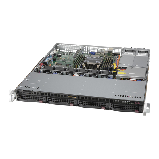
- Page 1 ® UPER The SC813/SC813M Chassis Series Installation Guide Rev. 1.0b...
-
Page 2: Table Of Contents
Chapter 2: Installation Procedures ... 2-1 Section 1: Installing components into the SC813 Chassis ... 2-1 A. Removing the top Cover of the SC813 Chassis ... 2-1 B. Accessing the SCA Drive Tray to Install a Hard Drive ... 2-2 C. -
Page 3: Chapter I: Introduction
Chapter 1: Introduction Chapter 1- Introduction A. Packing Lists A-1 The SC813 chassis The SC813 chassis contains the following: One (1) Slim CD ROM Drive [CDM-TEAC-24(B)] Four (4) SCA 1" drive trays [CSE-PT39-(B)] One (1) Slim 3.5" floppy drive [FPD-TEAC-S(B)]... -
Page 4: Front Panel Led Indicators
One (1) AC power cord Rail Packaging includes: One pair of rear inner slides to be installed on the chassis One pair of outer slides to be installed in the rack Two pairs of short brackets to be used on the front side of the outer slides (Note: One pair of short brackets include screw threads, and the other pair do not. - Page 5 C. Specifications of the SC813/SC813M Chassis C-1. Specifications of Model SC813S-500/500C 1U Rackmount Form Factor Dual Xeon Processors CPU Support ATX 12” x 13” Max. Motherboard Size Expansion Slots Four 1”hot-swap Ultra SCA or HD Bays 320/160 SCSI drive bays...
- Page 6 SC813/813M Chassis User's Guide D. Power Supply Specifications of the SC813/SC813M Chassis D-1. Power Supply Specifications of Power Supply Spec Mfr. Model # Mfr. Part # Rated AC Input Voltage Rated Input Frequency Rated Input Current Rated Output Power Maximum rated BTU Nominal Output Vlotage D-2.
-
Page 7: Chapter 2: Installation Procedures
Chapter 2: Installation Procedures Section 1: Installing Components into the SC813 Chassis A. Removing the top cover from the chassis Before installing any components, replacing chassis fans or accessing the motherboard, you will first need to remove the top cove from the chassis. - Page 8 B. Accessing the SCA Drive Tray and Installing a Hard Drive To install the SCA drive into the chassis, you need to first remove the SCA drive tray from the chassis so that the SCA drive can be installed in.
-
Page 9: Rail Installation
2. Align the four(4) square holes on the right inner slide against the hooks on the right side of the chassis as show below on the left. 3. Securely attach the slide to the chassis with two and repeat the steps 1-3 to install the left inner slide to the left side of the chassis. -
Page 10: Installing The Slide Assemblies Into The Rack
SC813 Chassis User's Guide C-3 Installing the Slide Assemblies to the Rack Procedures 1. After you have installed the short and long brackets to the outer slides, you are ready to install the whole slide assemblies (-outer slides with short and long brackets attached) to the rack. -
Page 11: Installing The Chassis Into The Rack
Inner slides Grooves of the outer slide assemblies 2. Push the chassis all the way to the back of the outer slide assemblies as shown below: (The plastic bezel is not included in the package.) Chapter 2: Installation Procedures Push the chassis into the... -
Page 12: Scsi ( Super) Gem Driver Installation Instructions For Windows Os
6) Click “Next” 2 times, uncheck both “Floppy disk drives” and “CD-ROM drives”. Then, select the item- “Specify a location,” and choose “Next”. 7) Click on “Browse” and choose D drive or wherever Supermicro Setup CD is in. 8) Choose “Qlogic” folder and click on “Open”. - Page 13 The SC813M series of chassis includes the SC813MS-420C, the SC813MT-420C, the SC813MS-300C and the SC813MT-300C. These chassis come equipped with a front side USB/COM port tray as part of the standard configuration. Supermicro has designed the SC813M series so that the USB/COM port tray can be replaced with a slim floppy drive.
- Page 14 SC813M Addendum Figure 1-1. Floppy Kit Adapter (1) Power cable (1) Screws (5) Rails (2) Small ribbon cable (1) Floppy drive ribbon cable (1)
-
Page 15: Installation Procedure
3. Find the release tab at the rear left of the USB/COM port tray. Push this tab in to unlock the tray, then push the tray out through the front of the chassis, along with the cables you just detached from the motherboard and which are still at- tached to the ports at the front of the tray. - Page 16 3. Connect the large (34-wire standard) floppy ribbon to the floppy adapter and route it through the chassis to connect it to the floppy connector on the mother- board. Make sure you route this cable in such a way that it does not block airflow or touch other components and is not close to any fans.
Need help?
Do you have a question about the SC813 Series and is the answer not in the manual?
Questions and answers