Table of Contents
Advertisement
Quick Links
Advertisement
Table of Contents

Subscribe to Our Youtube Channel
Related Manuals for Supero SC835 Chassis Series


Summary of Contents for Supero SC835 Chassis Series
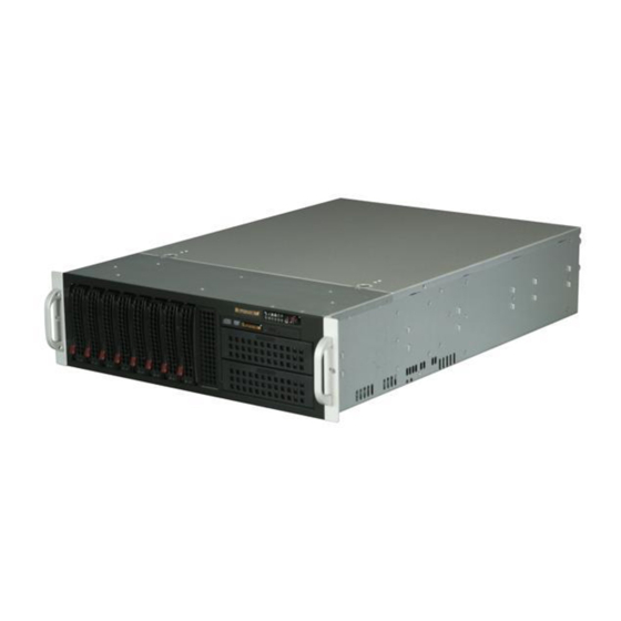
- Page 1 UPER ® SC835 Chassis Series SC835TQ - R800B USER’S MANUAL 1.0b...
- Page 2 SC835 Chassis Manual The information in this User’s Manual has been carefully reviewed and is believed to be accurate. The vendor assumes no responsibility for any inaccuracies that may be contained in this document, makes no commitment to update or to keep current the information in this manual, or to notify any person or organization of the updates.
-
Page 3: About This Manual
Preface Preface About This Manual This manual is written for professional system integrators and PC technicians. It provides information for the installation and use of the SC835 3U chassis. Installa- tion and maintenance should be performed by experienced technicians only. Supermicro’s SC835 3U chassis features a unique and highly-optimized design for dual-core Xeon platforms. -
Page 4: Manual Organization
SC835 Chassis Manual Manual Organization Chapter 1: Introduction The first chapter provides a checklist of the main components included with this chassis and describes the main features of the SC835 chassis. This chapter also includes contact information. Chapter 2: System Safety This chapter lists warnings, precautions, and system safety. -
Page 5: Table Of Contents
Preface Table of Contents Chapter 1 Introduction Overview ......................1-1 Shipping List ....................1-1 Part Numbers ....................1-1 Chassis Features .................... 1-2 CPU Support ....................1-2 Hard Drives ..................... 1-2 I/O Expansion slots ..................1-2 Peripheral Drives ..................... 1-2 Other Features ....................1-2 Contacting Supermicro .................. - Page 6 SC835 Chassis Manual Installing the Hard Drives ................5-3 Removing Hard Drive Carriers From the Chassis .......... 5-3 Installing a Hard Drive into the Hard Drive Carrier ......... 5-4 Installing the Motherboard ................5-6 Permanent and Optional Standoffs ..............5-6 Standoff Labeling ....................
- Page 7 Preface Appendix A SC835 Chassis Cables Appendix B SC835 Power Supply Specifications Appendix C SAS-833TQ Backplane Specifications...
- Page 8 SC835 Chassis Manual Notes viii...
-
Page 9: Chapter 1 Introduction
3U form factor. Shipping List Part Numbers Please visit the following link for the latest shipping lists and part numbers for your particular chassis model: http://www.supermicro.com/products/chassis/3U/?chs=835 SC835 Chassis Series Power Model I/O Slots Supply 8x 3.5" SAS... -
Page 10: Chassis Features
SC835 Chassis Manual Chassis Features The SC835 high-performance chassis includes the following features: CPU Support The SC835 chassis supports Intel and AMD Quad processors. Please refer to the motherboard specifications pages on our Web site for updates on supported proces- sors for this chassis, at www.supermicro.com. -
Page 11: Contacting Supermicro
Chapter 1: Introduction Contacting Supermicro Headquarters Address: Super Micro Computer, Inc. 980 Rock Ave. San Jose, CA 95131 U.S.A. Tel: +1 (408) 503-8000 Fax: +1 (408) 503-8008 Email: marketing@supermicro.com (General Information) support@supermicro.com (Technical Support) Web Site: www.supermicro.com Europe Address: Super Micro Computer B.V. Het Sterrenbeeld 28, 5215 ML 's-Hertogenbosch, The Netherlands Tel:... - Page 12 SC835 Chassis Manual Notes...
-
Page 13: Chapter 2 System Safety
Chapter 2: System Safety Chapter 2 System Safety Overview This chapter provides a quick setup checklist to get your chassis up and running. Following the steps in order given should enable you to have your chassis setup and operational within a minimal amount of time. These instructions assume that you are an experienced technician, familiar with common concepts and terminology. -
Page 14: Electrical Safety Precautions
SC835 Chassis Manual Electrical Safety Precautions Basic electrical safety precautions should be followed to protect yourself from harm and the SC835 from damage: • Be aware of the locations of the power on/off switch on the chassis as well as the room’s emergency power-off switch, disconnection switch or electrical outlet. -
Page 15: General Safety Precautions
Chapter 2: System Safety • Please handle used batteries carefully. Do not damage the battery in any way; a damaged battery may release hazardous materials into the environment. Do not discard a used battery in the garbage or a public landfill. Please comply with the regulations set up by your local hazardous waste management agency to dispose of your used battery properly. - Page 16 SC835 Chassis Manual • Use a grounded wrist strap designed to prevent static discharge. • Keep all components and printed circuit boards (PCBs) in their antistatic bags until ready for use. • Touch a grounded metal object before removing any board from its antistatic bag.
-
Page 17: Chapter 3 Chassis Components
Chapter 3: Chassis Components Chapter 3 Chassis Components Overview This chapter describes the most common components included with your chassis. Some components listed may not be included or compatible with your particular chassis model. For more information, see the installation instructions detailed later in this manual. -
Page 18: Mounting Rails
SC835 Chassis Manual Mounting Rails The SC835 can be placed in a rack for secure storage and use. To set up your rack, follow the step-by-step instructions included in this manual. Power Supply Each SC835 chassis model includes two redundant high-efficiency hot-swappable power supplies rated at 800 Watts. -
Page 19: Chapter 4 System Interface
Chapter 4: System Interface Chapter 4 System Interface Overview There are several LEDs on the control panel as well as others on the drive carriers to keep you constantly informed of the overall status of the system as well as the activity and health of specific components. -
Page 20: Control Panel Buttons
SC835 Chassis Manual Control Panel Buttons There are two push-buttons located on the front of the chassis. These are (in order from left to right) a reset button and a power on/off button. • Reset: The reset button is used to reboot the system. •... - Page 21 Chapter 4: System Interface • Overheat/Fan Fail: When this LED flashes it indicates a fan failure. When continuously on (not flashing) it indicates an overheat condition, which may be caused by cables obstructing the airflow in the system or the ambient room temperature being too warm.
-
Page 22: Drive Carrier Leds
SC835 Chassis Manual Drive Carrier LEDs Each SAS drive carrier has two LEDs. • Blue: When illuminated, this blue LED (on the front of the drive carrier) indicates drive activity. A connection to the SAS backplane enables this LED to blink on and off when that particular drive is being accessed. -
Page 23: Chapter 5 Chassis Setup And Maintenance
Chapter 5: Chassis Setup Chapter 5 Chassis Setup and Maintenance Overview This chapter details the basic steps required to install components to the chassis. The only tool you will need is a Phillips screwdriver. Print this page to use as a reference while setting up your chassis. -
Page 24: Removing The Chassis Cover
SC835 Chassis Manual Removing the Chassis Cover Release Tab Cover Screw Figure 5-1: Removing the Chassis Cover Removing the Chassis Cover Press the release tabs to release the cover from the locked position. Press both tabs at the same time. It may also be necessary to remove the chassis cover screw. -
Page 25: Installing The Hard Drives
Chapter 5: Chassis Setup Installing the Hard Drives The drives are mounted in drive carriers to simplify their installation and removal from the chassis. Removing Hard Drive Carriers From the Chassis Removing the Hard Drive Carriers Press the release button on the drive carrier. This extends the drive carrier handle. -
Page 26: Installing A Hard Drive Into The Hard Drive Carrier
SC835 Chassis Manual Installing a Hard Drive into the Hard Drive Carrier Installing a Hard Drive Remove the two screws securing the dummy drive to the drive carrier. Lift the dummy drive out of the drive carrier. Place the hard drive carrier on a flat, stable surface such as a desk, table, or work bench. - Page 27 Chapter 5: Chassis Setup SAS/SATA Hard Drive Hard Drive Carrier Use a hard, stable surface when installing the hard drive Figure 5-4: Installing a Drive into a Hard Drive Carrier...
-
Page 28: Installing The Motherboard
SC835 Chassis Manual Installing the Motherboard Permanent and Optional Standoffs Standoffs prevent short circuits by securing space between the motherboard and the chassis surface. The SC835 chassis includes permanent standoffs in locations used by most motherboards. These standoffs accept the rounded Phillips head screws included in the SC835 accessories packaging. -
Page 29: Motherboard Installation
Chapter 5: Chassis Setup Figure 5-5: Installing the Motherboard Motherboard Installation Installing the Motherboard Review the documentation that came with your motherboard. Become familiar with component placement, requirements, and precautions. Confirm that the power supply is disconnected and lay the chassis on a flat surface. -
Page 30: I/O Shield And Expansion Card Setup
SC835 Chassis Manual I/O Shield and Expansion Card Setup The SC835 chassis includes space for an I/O shield and up to seven add-on/ expansion cards. I/O Port Panel Expansion Card Slots Figure 5-6: SC835 Chassis Add-On Card Slots and I/O Ports Installing an Add-On or Expansion Card Installing Expansion Cards Remove the chassis cover. - Page 31 Chapter 5: Chassis Setup Installing an I/O Shield Installing an I/O Shield Remove the chassis cover. Locate the I/O shield. Depending on your motherboard, you must remove the existing I/O shield and replace it with the new one or use the existing the shield to slide the ports through.
-
Page 32: Installing The Air Shroud, Rear Fan, And Checking Air Flow
SC835 Chassis Manual Installing the Air Shroud, Rear Fan, and Checking Air Flow Figure 5-8: Installing the Air Shroud Air shrouds concentrate airflow to maximize fan efficiency. The SC835 chassis air shroud does not require screws to set it up. Note that the rear fans must be removed prior to installing the air shroud. -
Page 33: Chassis Maintenance
Chapter 5: Chassis Setup Chassis Maintenance System Fans Five heavy-duty fans provide cooling for the chassis. These fans circulate air through the chassis as a means of lowering the chassis' internal temperature. The SC835 chassis includes three front fans and two rear fans. SC835 chassis fans are fully hot-swappable. -
Page 34: Installing The Rear System Fans
SC835 Chassis Manual Rear System Fans The SC835 chassis includes three front fans and two rear fans. The front fans are pre-installed. The rear fans must be installed after motherboard and air shroud setup. Figure 5-10: Installing the Rear Fan Installing the Rear System Fans Installing a the Rear System Fans Confirm that the air shroud is correctly placed. -
Page 35: Checking The Server's Air Flow
Chapter 5: Chassis Setup Checking the Server's Air Flow Checking the Air Flow Make sure there are no objects to obstruct airflow in and out of the server. If necessary, route the cables through the cable rack. Do not operate the chassis without drives or drive trays in the drive bays. Use only recommended server parts. -
Page 36: Power Supply
SC835 Chassis Manual Power Supply The power supply for the SC835 chassis is redundant and hot-swappable, meaning that the power supply can be changed without powering down the system. Replacing the Power Supply Replacing the Power Supply The SC835 chassis includes a redundant power supply (at least two power modules). -
Page 37: Replacing The Power Distributor
Chapter 5: Chassis Setup Replacing the Power Distributor Redundant server chassis that are 2U in height or higher, require a power distribu- tor. The power distributor provides failover and power supply redundancy. In the unlikely event you must replace the power distributor, do following Installing the Power Distributor Power down the server and remove the plug from the wall socket or power strip. -
Page 38: Replacing The Dvd Or Cd-Rom Drive
SC835 Chassis Manual Replacing the DVD or CD-ROM Drive SC835 chassis models support either a slim 8x DVD-ROM, 24x CD or DVD-ROM drive. Use these instructions in this section in the unlikely event that you must replace any of these components. Figure 5-12: Installing the DVD-ROM, Front Panel, or CD-ROM Replacing or Installing the DVD Drive Installing a DVD or CD-ROM Drive... -
Page 39: Chapter 6 Rack Installation
Chapter 6: Rack Installation Chapter 6 Rack Installation Overview This chapter provides a quick setup checklist to get the chassis up and running. Following these steps in the order given should enable you to have the system operational within a minimum amount of time. Unpacking the System Inspect the box the chassis was shipped in and note if it was damaged in any way. -
Page 40: Rack Precautions
SC835 Chassis Manual • This product is for installation only in a Restricted Access Location (dedicated equipment rooms, service closets and similar environments). Warnings and Precautions! Rack Precautions • Ensure that the leveling jacks on the bottom of the rack are fully extended to the floor with the full weight of the rack resting on them. -
Page 41: Rack Mounting Considerations
Chapter 6: Rack Installation • Always keep the rack's front door and all panels and components on the servers closed when not servicing to maintain proper cooling. Rack Mounting Considerations Ambient Operating Temperature If installed in a closed or multi-unit rack assembly, the ambient operating tem- perature of the rack environment may be greater than the ambient temperature of the room. -
Page 42: Rack Mounting Instructions
SC835 Chassis Manual Rack Mounting Instructions This section provides information on installing the SC835 chassis into a rack unit with the quick-release rails provided. There are a variety of rack units on the market, which may mean the assembly procedure will differ slightly. You should also refer to the installation instructions that came with the rack unit you are using. -
Page 43: Installing The Inner Rail Extension
Chapter 6: Rack Installation Figure 6-2: Installing the Inner Rail Extensions Installing the Inner Rail Extension The SC835 chassis includes a set of inner rails in two sections: Inner rails and inner rail extensions. The inner rails are pre-attached to the chassis, and do not interfere with normal use of the chassis if you decide not to use a server rack. -
Page 44: Outer Rack Rails
SC835 Chassis Manual SCREW screw the handles the outer rails for secure purpose if necessary Figure 6-3: Assembling the Outer Rails Outer Rack Rails Outer rails attach to the rack and hold the chassis in place. The outer rails for the SC835 chassis extend between 30 inches and 33 inches. - Page 45 Chapter 6: Rack Installation SCREW Figure 6-4: Installing the Chassis into a Rack Installing the Chassis into a Rack Extend the outer rails as illustrated above. Align the inner rails of the chassis with the outer rails on the rack. Slide the inner rails into the outer rails, keeping the pressure even on both sides.
- Page 46 SC835 Chassis Manual Notes...
- Page 47 Appendix A: Chassis Cables Appendix A SC835 Chassis Cables A-1 Overview This appendix lists supported cables for your chassis system. It only includes the most commonly used components and configurations. For more compatible cables, refer to the manufacturer of the motherboard you are using and our Web site at: www.supermicro.com.
- Page 48 SC835 Chassis Manual A-3 Compatible Cables This section lists cables included with the SC835 Chassis packages. Alternate SAS Cables Some compatible motherboards have different connectors. If your motherboard has only one SAS connector that the SAS cables must share, use one of the following cables.
- Page 49 Appendix A: Chassis Cables Cascading/JBOD SAS Cables Use the following cables when setting up a cascading or JBOD system. Cable Name: SAS Cable Quantity: varies by setup Part #: CBL-0167L Placement: Internal cable Ports: Single Description: Internal cable. Connects the backplane to the Host Bus Adapter (HBA) or external port.
- Page 50 SC835 Chassis Manual Cable Name: SAS Cable Quantity: varies by setup Part #: CBL-0166L Placement: External cable Ports: Single or Dual Description: External cascading cable. Connects ports between servers. With most connectors, use one cable for single port connections and two cables for dual port connections.
- Page 51 Appendix A: Chassis Cables Extending Power Cables Although Supermicro chassis are designed with to be efficient and cost-effective, some compatible motherboards have power connectors located in different areas. To use these motherboards you may have to extend the power cables to the mother boards.
- Page 52 SC835 Chassis Manual Notes...
- Page 53 Appendix B: Power Supply Appendix B SC835 Power Supply Specifications This appendix lists power supply specifications for your chassis system. SC835TQ-R800B 800W (Redundant) MFR Part # PWS-801-1R 100 - 240V Rated AC Voltage 50 - 60Hz 10A - 4 Amp +5V standby 4 Amp +12V 66 Amp +5V 25 Amp...
-
Page 54: Power Supply Connections
SC835 Chassis Manual Power Supply Connections Connect each of the following cables, as required, by your motherboard manufac- turer. In some instances, some cables may not need to be connected. Power Supply Cables Name Number Connects to: Description 20-pin or 24-pin power cable pro- vides electricity to the motherboard. - Page 55 Appendix C: SAS-833TQ Backplane Specifications Appendix C SAS-833TQ Backplane Specifications To avoid personal injury and property damage, carefully follow all the safety steps listed below when accessing your system or handling the components. C-1 ESD Safety Guidelines Electrostatic Discharge (ESD) can damage electronic com ponents. To prevent dam- age to your system, it is important to handle it very carefully.
- Page 56 SC835 Chassis Manual C-3 An Important Note to Users • All images and layouts shown in this user's guide are based upon the latest PCB Revision available at the time of publishing. The card you have received may or may not look exactly the same as the graphics shown in this manual. C-4 Introduction to the SAS-833TQ Backplane The SAS-833TQ backplane has been designed to utilize the most up-to-date tech- nology available, providing your system with reliable, high-quality performance.
-
Page 57: Front Components
Appendix C: SAS-833TQ Backplane Specifications Jumper Settings and Pin Definitions C-5 Front Connectors and Jumpers Buzzer Figure C-1: Front Components Front Components Front Jumpers and Components: Upgrade Connector JP69 C Connector#1 JP37 and I C Connector#2 JP95 Sideband Connector#1 JP66 and Sideband Connector#2 JP68 Chip: MG9072 Power Connectors (4-pin): JP10 and JP13 Fan Connectors: JP54, JP56 and JP60... - Page 58 SC835 Chassis Manual SAS Port #2 J7 SAS Port #3 J8 SAS Port #4 J10 SAS Port #5 J12 SAS Port #6 J14 SAS Port #7 J16...
- Page 59 Appendix C: SAS-833TQ Backplane Specifications C-6 Front Connector and Pin Definitions 1. Upgrade Connector The upgrade connector, designated JP69, is used for manufacturer's diagnostic purposes only. 2. I C Connectors C Connector Pin Definitions The I C connectors, designated JP37 and Pin# Definition JP95, are used to monitor HDD activity and Data...
- Page 60 SC835 Chassis Manual 5. Backplane Main Power Connectors Backplane Main Power The 4-pin connectors, designated JP10 and 4-Pin Connector JP13 provide power to the backplane. See Pin# Definition the table on the right for pin definitions. +12V 2 and 3 Ground 6.
- Page 61 Appendix C: SAS-833TQ Backplane Specifications C-7 Front Jumper Locations and Pin Definitions JP35 JP84 JP97 JP99 JP98 JP61 JP62 JP63 Figure C-2: Jumper Locations Explanation of Jumpers Connector To modify the operation of the backplane, Pins jumpers can be used to choose between optional settings.
-
Page 62: Fan Jumper Settings
SC835 Chassis Manual Jumper Settings Jumper Jumper Settings Note 1-2: Reset JP35 MG9072 chip reset 2-3: No reset Socket Settings Socket Socket Setting Note Buzzer reset* JP18 Connected to front panel Press once to disable buzzer Press twice to enable buzzer *The buzzer sound indicates that a condition requiring immediate attention has occurred. - Page 63 Appendix C: SAS-833TQ Backplane Specifications C and SGPIO Modes and Jumper Settings This backplane can utilize I C or SGPIO. SGPIO is the default mode and can be used without making changes to your jumpers. The following information details which jumpers must be configured to use I C mode or restore your backplane to SGPIO mode.
- Page 64 SC835 Chassis Manual Front LED Indicators +5V LED FAN FAIL +12V LED #1 #2 #3 LEDs ALARM Figure C-3: Front LEDs Front Panel LEDs Normal State Specification Fan #1 fail Failure in Fan #1 Fan #2 fail Failure in Fan #2 Fan #3 fail Failure in Fan #3 Alarm #1...
- Page 65 Appendix C: SAS-833TQ Backplane Specifications C-8 Rear Connectors and LED Indicators SAS #0 SAS #1 SAS #2 SAS #3 SAS #4 SAS #5 SAS #6 SAS #7 Figure C-4: Rear Connectors Rear SAS/SATA Connectors Rear SAS/SATA Drive Connector Number SAS #0 SAS/SATA HDD #0 SAS #1 SAS/SATA HDD #1...
- Page 66 SC835 Chassis Manual Disclaimer (cont.) The products sold by Supermicro are not intended for and will not be used in life sup- port systems, medical equipment, nuclear facilities or systems, aircraft, aircraft devices, aircraft/emergency communication devices or other critical systems whose failure to per- form be reasonably expected to result in significant injury or loss of life or catastrophic property damage.
Need help?
Do you have a question about the SC835 Chassis Series and is the answer not in the manual?
Questions and answers