Table of Contents
Advertisement
Quick Links
Advertisement
Table of Contents

Related Manuals for iDTRONIC BLUEBOX ADVANT UHF


Summary of Contents for iDTRONIC BLUEBOX ADVANT UHF
- Page 1 RFID System M30 Form Factor BLUEBOX ADVANT UHF B5U033000E Page 1 of 54...
- Page 2 This document may be downloaded onto a computer, stored and duplicated as necessary to support the use of the related IDTRONIC products. Any other type of duplication, circulation or storage on data carriers in any manner not authorized by IDTRONIC represents a violation of the applicable copyright laws and shall be prosecuted.
- Page 3 Safety Instructions / Warning - Read before start-up! • The device may only be used for the intended purpose designed by the manufacturer. The operation manual should be conveniently kept available at all times for each user. • Unauthorized changes and the use of spare parts and additional devices that have not been sold or recommended by the manufacturer may cause fire, electric shocks or injuries.
- Page 4 IP65 This manual applies to the following devices: Description: Order Number: Read / write RFID UHF device with integrated antenna. 5227U CAN bus communication interface with CANopen protocol. EU (865 MHz … 868MHz) version. This manual is valid as of firmware version: Order Number Hardware Version Firmware Version...
-
Page 5: Table Of Contents
Table of Contents Introduction ..................6 Technical Specifications ..............7 Electrical Features ................ 7 2.1.1 Item 5227U ................7 Mechanical Features ..............7 Environmental Conditions .............. 8 Operating Features ................9 General Parameters ..............10 Configuration Parameters ............. 13 3.2.1 CAN Bus Interface .............. -
Page 6: Introduction
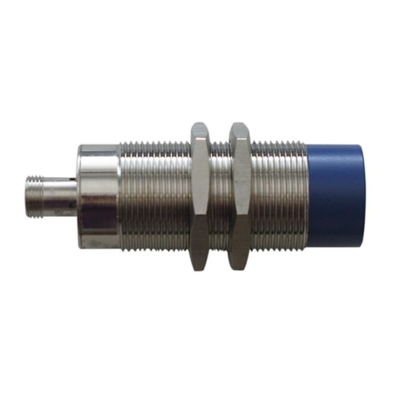
Introduction BLUEBOX GEN2 M30 UHF hereinafter named BLUEBOX is a little (dimensions of the cylindrical case D30 mm x 90.65 mm) read/write RFID device operating in the 840 MHz to 960 MHz frequency band and suitable for industrial application. The BLUEBOX communicates with a ‘host’... -
Page 7: Technical Specifications
Technical Specifications This section provides details on the technical specifications of the BLUEBOX. Electrical Features This section provides details on the electrical features of the BLUEBOX. 2.1.1 Item 5227U Power Supply 10 … 36 Vdc Power Rating 4W@24dBm Operating Frequency 865 MHz …... -
Page 8: Environmental Conditions
Environmental Conditions This section provides details on the environmental conditions of the BLUEBOX. Operating Temperature -20°C … +55°C Storage Temperature -40°C … +85°C Humidity Up to 95%, non condensing B5U033000E Page 8 of 54... -
Page 9: Operating Features
Operating Features In ‘continuous’ mode the BLUEBOX is characterized by the coexistence of 2 ‘parallel’ and asynchronous activities: the tag identification (inventory) and the communication with the ‘host’ system. The ‘continuous’ identification activity interacts with the communication activity through a buffer that contains the code of the last identified tags or that is empty indicating the absence of tags. -
Page 10: General Parameters
from the minimum RF output power to maximum RF output power or until it finds a tag, increasing the RF power of 1 dB every 500ms with fixed Q selection algorithm and Q=0. It is an ‘on request’ function which temporarily suspends the ‘continuous’... - Page 11 Sub-index 01h to 02h contains a configuration parameter. An attempt to change the value of the configuration parameter to any not supported value shall be responded with the SDO abort transfer service (abort code: 06090030h). See BLUEBOX user manual for value definition details. Parameter Description Range...
- Page 12 Sub-Index Description Number of parameters Data Type UNSIGNED8 Access PDO Mapping Value Range Default Value Save Object Sub-Index Description Filter time Data Type UNSIGNED8 Access PDO Mapping Value Range See value definition Default Value Save Object Sub-Index Description Functional flags Data Type UNSIGNED8 Access...
-
Page 13: Configuration Parameters
Configuration Parameters This section provides details on the configurable operational parameters of the BLUEBOX. 3.2.1 CAN Bus Interface The CAN bus interface parameters are managed through OD 1014h, 1015h, 20F0h and 20F2h as described in protocol technical manual. The changed CAN bus interface parameters become effective only after a reset of the BLUEBOX. - Page 14 Parameter Description Range Default damages due to incorrect or non-compliant country/region settings. RF Receive RF receive sensitivity in dBm. -51 … -87 dBm -76 dBm Sensitivity RF channel. Note that 0 value stands for default settings of the selected region. EU1: 0 …...
- Page 15 Parameter Description Range Default Note that this parameter become effective only after a reboot of the reader. The tag read count information. Tag Read Disabled Count Disabled Note that this parameter become effective Enabled Information only after a reboot of the reader. Sub-Index Parameter Description...
- Page 16 Sub-Index Parameter Description • Bit 4: Not used; • Bit 3: Max RSSI information; • Bit 2: Tag read count information; • Bit 1: RSSI information; • Bit 0: RF chip standby mode (0=enabled, 1=disabled). Object Descritpion: Index 2201h Name RF configuration Object Code RECORD...
- Page 17 Sub-Index Description RF output power Data Type UNSIGNED8 Access PDO Mapping Value Range See value definition Default Value Save Object Sub-Index Description RF input sensitivity Data Type UNSIGNED8 Access PDO Mapping Value Range See value definition Default Value Save Object Sub-Index Description RF channel...
- Page 18 Description RF antenna activation Data Type UNSIGNED8 Access PDO Mapping Value Range See value definition Default Value Save Object Sub-Index Description RF channel allocation time Data Type UNSIGNED8 Access PDO Mapping Value Range See value definition Default Value Save Object Sub-Index Description RF channel pause time...
- Page 19 Access PDO Mapping Value Range See value definition Default Value Save Object The EPC C1G2 (Class-1 Generation-2) parameters are managed through the OD 2202h. Value Definition: Sub-index 00h contains the number of valid object entries within the record. The number of valid objects entries shall be the number of the general configuration parameters.
- Page 20 Parameter Description Range Default The minimum allowed Q value in dynamic Q Q Initial 0 … 15 algorithm mode. The maximum allowed Q value in dynamic Q Q Final 0 … 15 algorithm mode. Q Adjust The maximum Q adjust rounds in dynamic Q 0 …...
- Page 21 Parameter Description Range Default Standard Single/Multi Tag with Custom Info). In case of Reserved or User bank selected 0 means no tag’s memory block access, in case of TID bank selected 0 means auto-length (class identifier, manufacturer identifier, serial number). Note that this parameter become effective only after a reboot of the reader.
- Page 22 Sub-Index Parameter Description Note that allowed values are: ReadAfterDetect ReadAfterDetect Inventory Mode Search Mod with Custom Info with Auto TID Fast Multi Tag, Dual Target, S Disabled Disabled Fast Single Tag Target Standard Multi Dual Target, S Tag, Standard Disabled Disabled Target Single Tag...
- Page 23 Sub-Index Parameter Description The Q value used in fixed Q selection algorithm or the starting Q Q Value value used in dynamic Q selection algorithm as defined in EPC Class 1 Generation 2 protocol (0 … 15). The minimum allowed Q value in dynamic Q selection algorithm Q Initial mode (0 …...
- Page 24 Sub-Index Parameter Description • Bit 7: Not used; • Bit 6: Not used; • Bit 5: Not used; • Bit 4: Not used; • Bit 3: Not used; • Bit 2: CRC field; • Bit 1: EPC field; • Bit 0: PC field. AFI management activation/deactivation: Use AFI •...
- Page 25 PDO Mapping Value Range See value definition Default Value Save Object Sub-Index Description R->T link frequency Data Type UNSIGNED8 Access PDO Mapping Value Range See value definition Default Value Save Object Sub-Index Description R->T bit coding Data Type UNSIGNED8 Access PDO Mapping Value Range See value definition...
- Page 26 Default Value Save Object Sub-Index Description Q value Data Type UNSIGNED8 Access PDO Mapping Value Range See value definition Default Value Save Object Sub-Index Description Q initial Data Type UNSIGNED8 Access PDO Mapping Value Range See value definition Default Value Save Object Sub-Index Description...
- Page 27 Save Object Sub-Index Description Q adjust rounds Data Type UNSIGNED8 Access PDO Mapping Value Range See value definition Default Value Save Object Sub-Index Description Inventory cycles Data Type UNSIGNED8 Access PDO Mapping Value Range See value definition Default Value Save Object Sub-Index Description Session...
- Page 28 Sub-Index Description Target Data Type UNSIGNED8 Access PDO Mapping Value Range See value definition Default Value Save Object Sub-Index Description EPC size Data Type UNSIGNED8 Access PDO Mapping Value Range See value definition Default Value Save Object Sub-Index Description ReadAfterDetect password Data Type UNSIGNED32 Access...
- Page 29 Description ReadAfterDetect bank Data Type UNSIGNED8 Access PDO Mapping Value Range See value definition Default Value Save Object Sub-Index Description ReadAfterDetect address Data Type UNSIGNED32 Access PDO Mapping Value Range UNSIGNED32 Default Value 00000000h Save Object Sub-Index Description ReadAfterDetect length Data Type UNSIGNED8 Access...
-
Page 30: Dynamic Power Management
Access PDO Mapping Value Range See value definition Default Value Save Object Sub-Index Description Use AFI Data Type UNSIGNED8 Access PDO Mapping Value Range See value definition Default Value Save Object Sub-Index Description Data Type UNSIGNED8 Access PDO Mapping Value Range UNSIGNED8 Default Value Save Object... - Page 31 Value Definition: Sub-index 00h contains the number of valid object entries within the record. The number of valid objects entries shall be the number of the general configuration parameters. Its value is 03h. Sub-index 01h to 03h contains a configuration parameter. An attempt to change the value of the configuration parameter to any not supported value shall be responded with the SDO abort transfer service (abort code: 06090030h).
- Page 32 Object Code RECORD Data Type Dynamic power configuration record Entry Description: Sub-Index Description Number of parameters Data Type UNSIGNED8 Access PDO Mapping Value Range Default Value Save Object Sub-Index Description Mode Data Type UNSIGNED8 Access PDO Mapping Value Range See value definition Default Value Save Object Sub-Index...
-
Page 33: Rf Tuning
Save Object Sub-Index Description Time step Data Type UNSIGNED8 Access PDO Mapping Value Range See value definition Default Value Save Object 3.2.4 RF Tuning This section provides details on the configurable dynamic power management parameters of the BLUEBOX Only items 5227U with hardware version 2 and firmware version 2.xx integrates the reconfigurable RF carrier leakage canceler feature and support RF tuning configuration parameters! The dynamic power management parameters are managed through the OD... - Page 34 Parameter Description Range Default Max Tune The maximum RF frequency hops on the same RF Frequency 0 … 250 frequency before RF tuning. Hops Min Tune The minimum RF frequency hops on different RF Frequency 0 … 250 frequency after RF tuning. Hops Tune The runtime RF tune hysteresis index of measured...
- Page 35 Default Value Save Object Sub-Index Description Max Tune Steps Data Type UNSIGNED8 Access PDO Mapping Value Range See value definition Default Value Save Object Sub-Index Description Max Tune Frequency Hops Data Type UNSIGNED8 Access PDO Mapping Value Range See value definition Default Value Save Object Sub-Index...
- Page 36 Save Object Sub-Index Description Tune Hysteresis Index Data Type UNSIGNED8 Access PDO Mapping Value Range See value definition Default Value Save Object B5U033000E Page 36 of 54...
-
Page 37: Installation
Installation This section provides details on the installation of the BLUEBOX. General Instructions • Several devices installed next to each other interfere if they are not correctly configured. • When mounting several nearby devices adhere to the minimum distances between them. •... -
Page 38: Mechanical Design
Observe the notes on installation when several RFID UHF devices are operated simultaneously. Mechanical Design Fixing Fix the device using the supplied nuts (M30) B5U033000E Page 38 of 54... -
Page 39: Mounting Distances
Mounting Distances Operating Mode Distance Side (A) Distance Front (B) Reading and writing at 100% transmitter power > 6.0mt > 10.0mt (simultaneous operation) Reading and writing at 100% transmitter power > 0.3mt > 0.3mt (alternating operation) Positioning of the Tags •... -
Page 40: Electrical Connections
Electrical Connections • The device must be connected by a skilled qualified person. • Device of protection class III. • Electric supply via SELV circuits only. • Disconnect power before connecting the device. • The IP rating indicated in the data sheet is only guaranteed if the M12 connectors are firmly screwed. - Page 41 To ensure interference-free operation, the device must be connected to an earth potential free from external voltage. Hereinafter a cross reference table between connection pin number and the color of the wires of a CAN bus 5-poles cable with 5-poles M12 A-coded female connector and open ended cable.
-
Page 42: Status Indications
Status Indications This section provides details on the status indications of the BLUEBOX. BLUEBOX uses one bicolor green/red LED. The following tables provides the indicator states and flash rates. LED State Description The LED shall be constantly on. The LED shall be constantly off. That shall indicate the iso-phase on and off with a frequency of Flickering approximately 10 Hz: on for approximately 50 ms and off for... - Page 43 Operating Status LED red LED green LED yellow Flashes (single Stopped and tag Flashes alternately flash) alternately detected with green LED with yellow LED Configuration or Blinking According to the current operating status hardware error CAN bus warning Flashes (single According to the current operating status limit reached flash)
-
Page 44: Antenna
Antenna This section provides details on the antenna of the BLUEBOX. BLUEBOX integrates an RF antenna inside the case. The read range of an RFID system always depends on various factors like antenna size, transponder size, transponder IC type, orientation between transponder and reader antenna, position of the transponder versus the reader antenna, noise environment, metallic environment, etc. -
Page 45: Maintenance, Repair And Disposal
Maintenance, Repair and Disposal If used correctly, no maintenance and repair measures are necessary • The device must only be repaired by the manufacturer. • After use dispose of the device in an environmentally friendly way in accordance with the applicable national regulations. •... -
Page 46: Regulatory Compliance
Regulatory Compliance This section gives information on the BLUEBOX regulatory compliance. CE Compliance BLUEBOX is in conformity with the relevant Union harmonisation legislation: • 2014/53/EU relating to the making available on the market of radio equipment • 2014/30/EU relating to electromagnetic compatibility •... -
Page 47: Mechanical Drawings
10 Mechanical Drawings All the dimensions are in mm. B5U033000E Page 47 of 54... -
Page 48: Document Revision History
11 Document Revision History Date Revision Description 12/09/18 1.00 First release. Updated the reader’s firmware versions object of this manual in preface section. Added the tag read count info activation flag in RF 22/10/18 1.01 configuration. Corrections in operating features and configuration parameters. - Page 49 Date Revision Description Added the regulatory compliance section. B5U033000E Page 49 of 54...
-
Page 50: Regions Of Operation
A. Regions of Operation BLUEBOX reader has been designed to work in various regions with differing frequency requirements. This document covers operation in North America and Europe. A.1. Operation in Europe For European operation, the BLUEBOX reader supports the frequency plan listed in the table below and is compliant with the ratified ETSI EN 302-208 specification V.3.1.0. -
Page 51: Operation In North America
Where: Maximum RF output power in dBm C,max Maximum ERP power of the antenna in dBm ERP,max Circular antenna gain in dBic Cable loss in dB A.2. Operation in North America The FCC specifies frequency hopping across the North American spectrum allocated to UHF RFID (902−928 MHz, with hopping occurring between 902.75−927.25 MHz in 500 KHz steps). -
Page 52: Operation In Brazil
Where: Maximum RF output power in dBm C,max Maximum ERP power of the antenna in dBm ERP,max Circular antenna gain in dBic Cable loss in dB A.3. Operation in Brazil The BLUEBOX operates over a subset of the FCC North American spectrum (902– 928 MHz, with specific frequency and channel usage dictated by regulations of each country. - Page 53 RF Channel Frequency [MHz] 917.75 918.25 918.75 919.25 919.75 920.25 920.75 921.25 921.75 922.25 922.75 923.25 923.75 924.25 924.75 925.25 925.75 926.25 926.75 927.25 Other RF channels and single channel selection are present only for test purposes and should not be used in normal operation! Brazil regulations describe the radiating power limits in relation to isotropic antenna and EIRP (Efficient Isotropic Radiating Power) is used as a measure.
- Page 54 power of P = 36dBm EIRP subject to a maximum conducted power of EIRP,max allowance of 30dBm at the antenna connector is allowed. The maximum BLUEBOX RF output power is defined as: - 2.15 + 5.15 + C C,max EIRP,max Where: Maximum RF output power in dBm C,max...
Need help?
Do you have a question about the BLUEBOX ADVANT UHF and is the answer not in the manual?
Questions and answers