Table of Contents
Advertisement
Quick Links
VNM EC 201 • Setup Guide
The Extron VNM Enterprise Controller 201 is a dedicated control device for managing large VN-Matrix systems. The controller
allows users to view, manage, and dynamically control multiple VN-Matrix systems and networked VN-Matrix domains from a
single user interface.
This guide provides basic instructions for an experienced installer to configure and operate a single VNM Enterprise
Controller 201 in a basic VN-Matrix system.
NOTE:
See the VNM Enterprise Controller 201 User Guide, VN-Matrix 200 Series User Guide, VN-Matrix 225 Series User
Guide, VN-Matrix 250 User Guide, VN-Matrix 300 User Guide, and the VN-Matrix 325 User Guide for complete installation,
network configuration, and mounting information.
Step 1 — Mount the VNM Enterprise Controller 201
Disconnect power to the VNM Enterprise Controller 201 and turn off all devices that will be connected to it. The controller is
housed in a half rack wide, 11.5 inches deep, 1U high metal enclosure that can be rack mounted or placed on a table (with the
provided rubber feet attached). Select a suitable mounting option and location, and follow the instructions provided with the
mounting kit.
Step 2 — Cable the Controller
A
B
C
100 - 240V
0.5A MAX~
OUTPUTS
DISPLAYPORT
2
HDMI
50 - 60Hz~
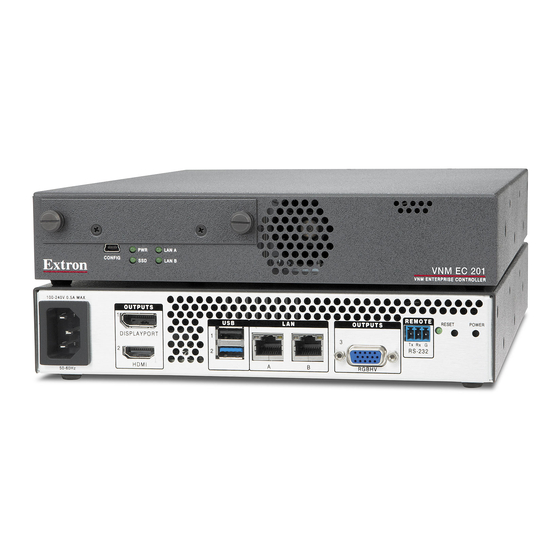
Figure 1.
VN Matrix Enterprise Controller 201, Rear and Front Panels
A
AC power — IEC connector. Standard AC power: 100 to 240 VAC, at 50 to 60 Hz.
B
DisplayPort video output — Connect a compatible DisplayPort display for troubleshooting.
C
HDMI video output — Connect a compatible HDMI display for troubleshooting.
D
USB ports — Two USB port connections for one mouse and one keyboard.
E
Ethernet connector — LAN A for connection to a standard LAN.
F
Ethernet connector — LAN B is not required for normal operation.
G
VGA Connector — One configurable analog output 15-pin HD (VGA) connector for use in troubleshooting.
H
Serial Connector — Provides remote control using RS-232 and the High Level Interface (HLI) command control protocol that
allows users to interface a third party control system with the devices on a VN-Matrix network.
I
Reset button and LED — The VNM Enterprise Controller 201 has two reset modes to restore configuration settings or all
settings back to factory defaults. The LED indicates the desired reset mode, and provides the reset status during the reset
operation. For information on using the reset mode, see the VN Matrix Enterprise Controller 201 User Guide.
J
Recessed power button — Press once to initiate a safe shutdown of the system.
K
USB mini-B config port — Connect to a PC for Simple Instruction Set (SIS™) control.
L
Status LEDs — Four LEDs provide the status of the VNM EC 201.
•
Network Activity LED (A) — Lights steadily when a network link is established. Blinks to indicate activity.
•
Network Activity LED (B) — Lights steadily when a network link is established. Blinks to indicate activity.
•
Drive Activity LED — Blinks to indicate drive activity.
•
Power LED — Lights when the controller is powered.
M
Solid State Drive (SSD) — This removable drive holds the operating system (OS) and software required for operation.
D
E
F
G
H I J
REMOTE
USB
LAN
OUTPUTS
1
3
Tx
Rx
RS-232
2
A
B
RGBHV
J J
K
L
RESET
POWER
OWER
G
PWR
CONFIG
SSD
M
LAN A
LAN B
VNM EC 201
VNM ENTERPRISE CONTROLLER
1
Advertisement
Table of Contents

Related Manuals for Extron electronics VNM EC 201


Summary of Contents for Extron electronics VNM EC 201
- Page 1 Recessed power button — Press once to initiate a safe shutdown of the system. USB mini-B config port — Connect to a PC for Simple Instruction Set (SIS™) control. Status LEDs — Four LEDs provide the status of the VNM EC 201. •...
- Page 2 VNM EC 201 • Setup Guide (Continued) Initial EC 201 Installation and Configuration Step 1 — Determine the Network Settings Before any device is connected to a network, the default network settings of each device must be changed. On an existing network, check with the network administrator for a range of available IP addresses.
- Page 3 Use the following procedure to change the network settings of the VNM Enterprise Controller 201, if necessary. Configure the network settings of a control PC to use an IP address within 192.168.254.1 to 192.168.254.253 and a subnet mask of 255.255.255.0. Connect the control PC to the VN-Matrix network. Open a web browser on the control PC and enter the IP address of the VNM Enterprise Controller 201 in the address bar (for example, http://192.168.254.254).
- Page 4 Step 5 — Configure the Network Click Add ( ) and enter the correct IP address of the VNM EC 201 previously created in Settings of the VNM Enterprise Controller 201 on page 2 into the window that opens and click OK.
- Page 5 Step 7 — Assign VN-Matrix 200 / 225 / 300 / 325 Devices as Encoders and Decoders If necessary, log in, then click the Devices tab (see figure 7, ). The Devices page opens. Figure 7. Devices Page — Mode Selection Menu Click the check box in the same row as the desired device.
- Page 6 VNM EC 201 • Setup Guide (Continued) Decoder Configuration Click the Devices tab (see figure 7, on page 5). The Devices page opens. Select a decoder (see figure 7, ). At the bottom of the page, several menus are now available (see figure 10).
- Page 7 Updating the VNM Enterprise Controller 201 License Updating the license of the VNM Enterprise Controller 201 is sometimes necessary to enable certain features of the system. Use the following procedure to update the license. Click the Configuration tab (see figure 12, ).
- Page 8 For information on safety guidelines, regulatory compliances, EMI/EMF compatibility, accessibility, and related topics, see the Extron Safety and Regulatory Compliance Guide on the Extron website. www.extron.com © 2019 Extron Electronics — All rights reserved. 68-2660-51 Rev. A All trademarks mentioned are the property of their respective owners. 06 19...
Need help?
Do you have a question about the VNM EC 201 and is the answer not in the manual?
Questions and answers