WAGO I/O-SYSTEM 750 Series Manual
24v dc power supply/fuse/diagn. supply module dc 24 v, fuse, diagnostics
Hide thumbs
Also See for I/O-SYSTEM 750 Series:

Related Manuals for WAGO I/O-SYSTEM 750 Series


Summary of Contents for WAGO I/O-SYSTEM 750 Series
- Page 1 Manual WAGO-I/O-SYSTEM 750 24V DC Power Supply/Fuse/Diagn. 750-610 Supply Module DC 24 V, Fuse, Diagnostics Version 1.1.0...
- Page 2 WAGO-I/O-SYSTEM 750 750-610 24V DC Power Supply/Fuse/Diagn. © 2015 by WAGO Kontakttechnik GmbH & Co. KG All rights reserved. WAGO Kontakttechnik GmbH & Co. KG Hansastraße 27 D-32423 Minden Phone: +49 (0) 571/8 87 – 0 Fax: +49 (0) 571/8 87 – 1 69 E-Mail: info@wago.com...
-
Page 3: Table Of Contents
2.1.1 Subject to Changes ................9 2.1.2 Personnel Qualifications ............... 9 2.1.3 Use of the WAGO-I/O-SYSTEM 750 in Compliance with Underlying Provisions ..................... 9 2.1.4 Technical Condition of Specified Devices ......... 10 Safety Advice (Precautions) ..............11 Device Description ..................13 View ...................... - Page 4 Table of Contents WAGO-I/O-SYSTEM 750 750-610 24V DC Power Supply/Fuse/Diagn. Marking Configuration Examples ............33 8.1.1 Marking for Europe According to ATEX and IEC-Ex ...... 33 8.1.2 Marking for America According to NEC 500 ........38 Installation Regulations ................39 8.2.1...
-
Page 5: Notes About This Documentation
Manual by third parties that violate pertinent copyright provisions is prohibited. Reproduction, translation, electronic and phototechnical filing/archiving (e.g., photocopying) as well as any amendments require the written consent of WAGO Kontakttechnik GmbH & Co. KG, Minden, Germany. Non-observance will involve the right to assert damage claims. Manual... -
Page 6: Symbols
Notes about this Documentation WAGO-I/O-SYSTEM 750 750-610 24V DC Power Supply/Fuse/Diagn. Symbols Personal Injury! Indicates a high-risk, imminently hazardous situation which, if not avoided, will result in death or serious injury. Personal Injury Caused by Electric Current! Indicates a high-risk, imminently hazardous situation which, if not avoided, will result in death or serious injury. - Page 7 WAGO-I/O-SYSTEM 750 Notes about this Documentation 750-610 24V DC Power Supply/Fuse/Diagn. Additional Information: Refers to additional information which is not an integral part of this documentation (e.g., the Internet). Manual Version 1.1.0...
-
Page 8: Number Notation
Font Conventions Table 2: Font Conventions Font Type Indicates italic Names of paths and data files are marked in italic-type. e.g.: C:\Program Files\WAGO Software Menu Menu items are marked in bold letters. e.g.: Save > A greater-than sign between two names means the selection of a menu item from a menu. -
Page 9: Important Notes
2.1.1 Subject to Changes WAGO Kontakttechnik GmbH & Co. KG reserves the right to provide for any alterations or modifications that serve to increase the efficiency of technical progress. WAGO Kontakttechnik GmbH & Co. KG owns all rights arising from the granting of patents or from the legal protection of utility patents. -
Page 10: Technical Condition Of Specified Devices
WAGO-I/O-SYSTEM 750 750-610 24V DC Power Supply/Fuse/Diagn. Appropriate housing (per 94/9/EG) is required when operating the WAGO-I/O- SYSTEM 750 in hazardous environments. Please note that a prototype test certificate must be obtained that confirms the correct installation of the system in a housing or switch cabinet. -
Page 11: Safety Advice (Precautions)
Install the device only in appropriate housings, cabinets or in electrical operation rooms! The WAGO-I/O-SYSTEM 750 and its components are an open system. As such, install the system and its components exclusively in appropriate housings, cabinets or in electrical operation rooms. Allow access to such equipment and fixtures to authorized, qualified staff only by means of specific keys or tools. - Page 12 Important Notes WAGO-I/O-SYSTEM 750 750-610 24V DC Power Supply/Fuse/Diagn. Do not use any contact spray! Do not use any contact spray. The spray may impair contact area functionality in connection with contamination. Do not reverse the polarity of connection lines! Avoid reverse polarity of data and power supply lines, as this may damage the devices involved.
-
Page 13: Device Description
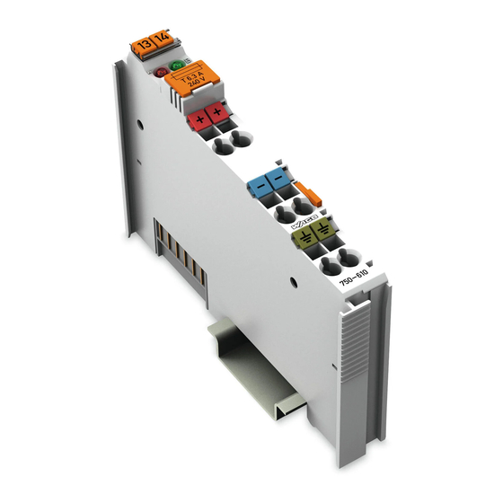
WAGO-I/O-SYSTEM 750 Device Description 750-610 24V DC Power Supply/Fuse/Diagn. Device Description 750-610 (24V DC Power Supply/Fuse/Diagn.) The supply module750-610 (24V DC Power Supply/Fuse/Diagn.) provides 24 VDC field side power to the downstream modules. The power supply is derived from an external source via the 24 V, 0 V and ground (earth) terminals. -
Page 14: View
Device Description WAGO-I/O-SYSTEM 750 750-610 24V DC Power Supply/Fuse/Diagn. View Figure 1: View Table 3: Legend for Figure “View” Pos. Description Details See Section Marking possibility with Mini- Status LEDs “Device Description” > “Display Elements” Data contacts “Device Description” > “Connectors”... -
Page 15: Connectors
WAGO-I/O-SYSTEM 750 Device Description 750-610 24V DC Power Supply/Fuse/Diagn. Connectors 3.2.1 Data Contacts/Internal Bus Communication between the fieldbus coupler/controller and the I/O modules as well as the system supply of the I/O modules is carried out via the internal bus. It is comprised of 6 data contacts, which are available as self-cleaning gold spring contacts. -
Page 16: Power Jumper Contacts/Field Supply
Device Description WAGO-I/O-SYSTEM 750 750-610 24V DC Power Supply/Fuse/Diagn. 3.2.2 Power Jumper Contacts/Field Supply Figure 3: Power Jumper Contacts Table 4: Legend for Figure “Power Jumper Contacts” Contact Type Function Potential transmission (U Spring contact for field supply Potential transmission (0 V) -
Page 17: Cage Clamp ® Connectors
WAGO-I/O-SYSTEM 750 Device Description 750-610 24V DC Power Supply/Fuse/Diagn. ® 3.2.3 CAGE CLAMP Connectors </dg_ ® Figure 4: CAGE CLAMP connections ® Table 5: Key for "CAGE CLAMP Connections" figure Designation Termination Function 24 V Power supply: 24V field supply... -
Page 18: Display Elements
Device Description WAGO-I/O-SYSTEM 750 750-610 24V DC Power Supply/Fuse/Diagn. Display Elements </dg_ Figure 5: Indicating elements Table :6 Key for the “Display elements” figure Condition Description Red/off Error status of the fuse Green/off Status of the operating voltage power jumper... -
Page 19: Technical Data
WAGO-I/O-SYSTEM 750 Device Description 750-610 24V DC Power Supply/Fuse/Diagn. Technical Data </dg_ 3.6.1 Device Data Table 7: Technical Data, Device Width 12 mm Height (from upper edge of DIN 35 rail) 64 mm Depth 100 mm Weight approx. 51.5 g 3.6.2... -
Page 20: Climatic Environmental Conditions
Device Description WAGO-I/O-SYSTEM 750 750-610 24V DC Power Supply/Fuse/Diagn. 3.6.4 Climatic Environmental Conditions Table 12: Technical Data – Climatic Environmental Conditions Operating temperature range 0 °C … 55 °C Storage temperature range −25 °C … +85 °C Relative humidity without condensation Max. 95 % Resistance to harmful substances Acc. -
Page 21: Approvals
750-610 24V DC Power Supply/Fuse/Diagn. Approvals More information about approvals. Detailed references to the approvals are listed in the document “Overview Approvals WAGO-I/O-SYSTEM 750”, which you can find via the internet under: www.wago.com > SERVICES > DOWNLOADS > Additional documentation and information on automation products > WAGO-I/O-SYSTEM 750 >... - Page 22 Device Description WAGO-I/O-SYSTEM 750 750-610 24V DC Power Supply/Fuse/Diagn. The following ship approvals have been granted to 750-610 I/O modules: ABS (American Bureau of Shipping) Federal Maritime and Hydrographic Agency BV (Bureau Veritas) DNV (Det Norske Veritas) Class B GL (Germanischer Lloyd) Cat.
-
Page 23: Standards And Guidelines
WAGO-I/O-SYSTEM 750 Device Description 750-610 24V DC Power Supply/Fuse/Diagn. Standards and Guidelines 750-610 I/O modules meet the following requirements on emission and immunity of interference: EMC CE-Emission of interference acc. to EN 61000-6-4 EMC CE-Immunity to interference acc. to EN 61000-6-2... -
Page 24: Process Image
Process Image WAGO-I/O-SYSTEM 750 750-610 24V DC Power Supply/Fuse/Diagn. Process Image </dg_ Table 13: Input Bits Bit 1 Bit 0 FUSE SUPPLY SUPPLY Operating voltage monitoring 0: The 24V power supply is not applied to the power contacts or the fuse is defective. -
Page 25: Mounting
Don't forget the bus end module! Always plug a bus end module 750-600 onto the end of the fieldbus node! You must always use a bus end module at all fieldbus nodes with WAGO-I/O- SYSTEM 750 fieldbus couplers/controllers to guarantee proper data transfer. -
Page 26: Inserting And Removing Devices
Mounting WAGO-I/O-SYSTEM 750 750-610 24V DC Power Supply/Fuse/Diagn. Inserting and Removing Devices Perform work on devices only if they are de-energized! Working on energized devices can damage them. Therefore, turn off the power supply before working on the devices. 5.2.1... -
Page 27: Removing The I/O Module
WAGO-I/O-SYSTEM 750 Mounting 750-610 24V DC Power Supply/Fuse/Diagn. 5.2.2 Removing the I/O Module Remove the I/O module from the assembly by pulling the release tab. Figure 9: Removing the I/O Module (Example) Electrical connections for data or power jumper contacts are disconnected when removing the I/O module. -
Page 28: Connect Devices
Only one conductor may be connected to each CAGE CLAMP Do not connect more than one conductor at one single connection! If more than one conductor must be routed to one connection, these must be connected in an up-circuit wiring assembly, for example using WAGO feed- through terminals. Exception: If it is unavoidable to jointly connect 2 conductors, then you must use a ferrule to join the wires together. -
Page 29: Power Supply Concept
Detailed information on power supply regulations is available in the document "Power Supply". You can download the document on the Internet www.wago.com Service Downloads Additional Documentation and Information on Automation Products WAGO-I/O-SYSTEM 750 System Description. 6.2.1 Supplementary Power Supply Regulations... -
Page 30: Startup And Service
Startup and Service WAGO-I/O-SYSTEM 750 750-610 24V DC Power Supply/Fuse/Diagn. </dg_ Startup and Service </dg_ Install a new, suitable fuse before initial startup or if the fuse is defective. Only uses fuses with the specification 5 × 20 mm, T 6.3 A. -
Page 31: Figure 13: Opening The Fuse Holder
WAGO-I/O-SYSTEM 750 Startup and Service 750-610 24V DC Power Supply/Fuse/Diagn. Figure 13: Opening the fuse holder Remove the old fuse (if any) and install the new fuse. Figure 14: Replacing the fuse Close the fuse holder. Push the fuse holder back into the I/O module housing. -
Page 32: Use In Hazardous Environments
WAGO-I/O-SYSTEM 750 750-610 24V DC Power Supply/Fuse/Diagn. Use in Hazardous Environments The WAGO-I/O-SYSTEM 750 (electrical equipment) is designed for use in Zone 2 hazardous areas. The following sections include both the general identification of components (devices) and the installation regulations to be observed. The individual subsections of the “Installation Regulations”... -
Page 33: Marking Configuration Examples
WAGO-I/O-SYSTEM 750 Use in Hazardous Environments 750-610 24V DC Power Supply/Fuse/Diagn. Marking Configuration Examples 8.1.1 Marking for Europe According to ATEX and IEC-Ex Figure 15: Side Marking Example for Approved I/O Modules According to ATEX and IECEx Figure 16: Text Detail – Marking Example for Approved I/O Modules According to ATEX and IECEx. -
Page 34: Table 14: Description Of Marking Example For Approved I/O Modules According To Atex And Iecex
Use in Hazardous Environments WAGO-I/O-SYSTEM 750 750-610 24V DC Power Supply/Fuse/Diagn. Table 14: Description of Marking Example for Approved I/O Modules According to ATEX and IECEx Printing on Text Description TÜV 07 ATEX 554086 X Approving authority and certificate numbers IECEx TUN 09.0001 X... -
Page 35: Figure 17: Side Marking Example For Approved Ex I I/O Modules According To Atex And Iecex
WAGO-I/O-SYSTEM 750 Use in Hazardous Environments 750-610 24V DC Power Supply/Fuse/Diagn. Figure 17: Side Marking Example for Approved Ex i I/O Modules According to ATEX and IECEx. Figure 18: Text Detail – Marking Example for Approved Ex i I/O Modules According to ATEX and IECEx. -
Page 36: Table 15: Description Of Marking Example For Approved Ex I I/O Modules According To Atex And Iecex
Use in Hazardous Environments WAGO-I/O-SYSTEM 750 750-610 24V DC Power Supply/Fuse/Diagn. Table 15: Description of Marking Example for Approved Ex i I/O Modules According to ATEX and IECEx Inscription Text Description TÜV 12 ATEX 106032 X IECEx TUN 12.0039 X... - Page 37 WAGO-I/O-SYSTEM 750 Use in Hazardous Environments 750-610 24V DC Power Supply/Fuse/Diagn. Table 15: Description of Marking Example for Approved Ex i I/O Modules According to ATEX and IECEx Gases Equipment group: All except mining 3(1)G Category 3 (Zone 2) equipment containing a safety...
-
Page 38: Marking For America According To Nec 500
Use in Hazardous Environments WAGO-I/O-SYSTEM 750 750-610 24V DC Power Supply/Fuse/Diagn. 8.1.2 Marking for America According to NEC 500 Figure 19: Side Marking Example for I/O Modules According to NEC 500 Figure 20: Text Detail – Marking Example for Approved I/O Modules According to NEC 500... -
Page 39: Installation Regulations
WAGO-I/O-SYSTEM 750 Use in Hazardous Environments 750-610 24V DC Power Supply/Fuse/Diagn. Installation Regulations For the installation and operation of electrical equipment in hazardous areas, the valid national and international rules and regulations which are applicable at the installation location must be carefully followed. -
Page 40: Special Conditions For Safe Use (Atex Certificate Tüv 07 Atex 554086 X)
ATEX 554086 X) For use as Gc- or Dc-apparatus (in zone 2 or 22) the Field bus Independent I/O Modules WAGO-I/O-SYSTEM 750-*** shall be erected in an enclosure that fulfils the requirements of the applicable standards (see the marking) EN 60079-0, EN 60079-15 and EN 60079-31. -
Page 41: Special Conditions For Safe Use (Atex Certificate Tüv 12 Atex 106032 X)
1. For the use as an apparatus which requires an Equipment Protection Level (EPL) of Gc or Dc (for the use in zone 2 or 22) the modules of the WAGO-I/O-SYSTEM 750-*** Ex i must be erected in an enclosure that meets the requirements of the applicable standards (see the marking) EN 60079-0, EN 60079-11, EN 60079-15 and EN 60079-31. -
Page 42: Special Conditions For Safe Use (Iec-Ex Certificate Tun 09.0001
09.0001 X) For use as Gc- or Dc-apparatus (in zone 2 or 22) the Field bus Independent I/O Modules WAGO-I/O-SYSTEM 750-*** shall be erected in an enclosure that fulfils the requirements of the applicable standards (see the marking) IEC 60079-0, IEC 60079-15 and IEC 60079-31. -
Page 43: Special Conditions For Safe Use (Iec-Ex Certificate Iecex Tun 12.0039 X)
For the use as an apparatus which requires an Equipment Protection Level (EPL) of Gc or Dc (for the use in zone 2 or 22) the modules of the WAGO-I/O-SYSTEM 750-*** Ex i must be erected in an enclosure that meets the requirements of the applicable standards (see the marking) IEC 60079-0, IEC 60079-11, IEC 60079-15 and IEC 60079-31. -
Page 44: Special Conditions For Safe Use According To Ansi/Isa
Use in Hazardous Environments WAGO-I/O-SYSTEM 750 750-610 24V DC Power Supply/Fuse/Diagn. 8.2.5 Special Conditions for Safe Use According to ANSI/ISA 12.12.01 “This equipment is suitable for use in Class I, Division 2, Groups A, B, C, D or non-hazardous locations only.”... -
Page 45: List Of Figures
WAGO-I/O-SYSTEM 750 List of Figures 750-610 24V DC Power Supply/Fuse/Diagn. List of Figures Figure 1: View ....................... 14 Figure 2: Data Contacts ..................15 Figure 3: Power Jumper Contacts ................. 16 ® Figure 4: CAGE CLAMP connections ..............17 Figure 5: Indicating elements ................18 Figure 6: Schematic diagram ................. -
Page 46: List Of Tables
List of Tables WAGO-I/O-SYSTEM 750 750-610 24V DC Power Supply/Fuse/Diagn. List of Tables Table 1: Number Notation ..................8 Table 2: Font Conventions ..................8 Table 3: Legend for Figure “View” ..............14 Table 4: Legend for Figure “Power Jumper Contacts” ......... 16 ®... - Page 47 WAGO-I/O-SYSTEM 750 750-610 24V DC Power Supply/Fuse/Diagn. Manual Version 1.1.0...
- Page 48 WAGO Kontakttechnik GmbH & Co. KG Postfach 2880 • D-32385 Minden Hansastraße 27 • D-32423 Minden Phone: +49/5 71/8 87 – 0 Fax: +49/5 71/8 87 – 1 69 E-Mail: info@wago.com Internet: http://www.wago.com...
Need help?
Do you have a question about the I/O-SYSTEM 750 Series and is the answer not in the manual?
Questions and answers