Emerson FB1100 Instruction Manual
Flow computer
Hide thumbs
Also See for FB1100:
- Instruction manual (82 pages) ,
- Quick start manual (35 pages) ,
- Field replacement manual (20 pages)

Related Manuals for Emerson FB1100


Summary of Contents for Emerson FB1100
- Page 1 Emerson FB1100 Flow Computer Instruction Manual D301752X012 August 2020 Emerson FB1100 Flow Computer Instruction Manual Remote Automation Solutions...
- Page 2 Our full-time professional instructors can conduct classroom training at several of our corporate offices, at your site, or even at your regional Emerson office. You can also receive the same quality training via our live, interactive Emerson Virtual Classroom and save on travel costs. For our complete schedule and further information, contact the Remote Automation Solutions Training Department at 800-338-8158 or email us at education@emerson.com.
-
Page 3: Table Of Contents
Emerson FB1100 Flow Computer Instruction Manual D301752X012 August 2020 Contents Section 1: Introduction Safety Labels ........................3 Features ..........................3 Central Processing Unit (CPU) ....................4 1.3.1 Memory ........................4 ... - Page 4 Emerson FB1100 Flow Computer Instruction Manual D301752X012 August 2020 2.13 Connecting Communication Ports ................37 2.13.1 Connecting to COM1 ..................... 38 2.13.2 Connecting to COM2 and COM3 ................39 2.14 Connecting the RTD ....................42 ...
-
Page 5: Introduction
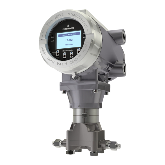
RoHS2 Compliance The Emerson FB1100 Flow Computer measures pressure, differential pressure, and temperature for a single meter run of natural gas. This manual describes how to install and configure the Emerson FB1100 Flow Computer hardware. For information on using the FBxConnect ™... - Page 6 Emerson FB1100 Flow Computer Instruction Manual D301752X012 August 2020 Figure 1-1: FB1100 Flow Computer HMI module Front end cap (cover) Data plate Rear end cap (cover) Conduit fittings Enclosure Sensor module Introduction...
-
Page 7: Safety Labels
Failure to do so may result in injury to personnel or cause damage to the equipment. SAFETY FIRST General instructions and safety reminders. Features The FB1100 Flow Computer includes the following key features: Enclosure suitable for use in Class I Division 1 explosion proof and Ex db Zone 1 flame-proof environments ... -
Page 8: Central Processing Unit (Cpu)
I/O and communication wiring. ATEX installations use a ¾ in NPT to M20 thread reducer. Unused apertures shall be closed with suitable blanking elements. The FB1100 Flow Computer can operate in an unprotected outdoor environment. Wiring for I/O, communications, and power enters the enclosure through the four conduit fittings with appropriate protective seals and connects to the terminal plate. -
Page 9: Physical Security
D301752X012 August 2020 The FB1100 Flow Computer has North American certification for Class I Division 1 Groups C and D (explosion proof) and Class I Division 2 Groups A, B, C and D (non-incendive) hazardous locations or non-hazardous locations. See... -
Page 10: Power Options
Important Use only batteries supplied with the flow computer or sold by Emerson Remote Automation Solutions as spare parts for this flow computer. If you substitute a battery you obtain elsewhere you will void your certification unless it is the identical part from the same manufacturer as that supplied with the flow computer from Emerson. -
Page 11: Communications
Emerson FB1100 Flow Computer Instruction Manual D301752X012 August 2020 Communications The flow computer includes three serial communication ports. The serial ports allow communication using DNP3, Modbus, BSAP, and ROC protocols. Table 1-3: Serial Ports Port Type COM1 Serial communications RS-232, RS-485 (2-wire), RS-485/422 (4-wire) ... -
Page 12: Fbxwifi™ Communications
Emerson FB1100 Flow Computer Instruction Manual D301752X012 August 2020 Figure 1-3: HMI Module with LCD Figure 1-4: HMI Module without LCD Note If your flow computer does not include the LCD option, you still have the status LEDs and a single IR... -
Page 13: Software Tools
Autonomous Measurement Mode You can configure the FB1100 Flow Computer to operate as a low power measurement device that operates independently for one year. In this autonomous measurement mode, the flow computer operates similarly to earlier generation chart recorders, collecting data from non-critical, low-flow applications and storing it for later retrieval. - Page 14 Emerson FB1100 Flow Computer Instruction Manual D301752X012 August 2020 Introduction...
-
Page 15: Installation
Class I Division 2 installations; Appendix B contains special information for Class I Division 1 installations. For Europe the FB1100 Flow Computer has certifications for Ex db Zone 1 flame-proof and for Ex nA Zone 2 non-sparking installations and non-hazardous locations only. Appendix C contains special information for Ex nA Zone 2 installations;... -
Page 16: Environmental Specifications
Emerson FB1100 Flow Computer Instruction Manual D301752X012 August 2020 Environmental Specifications This section summarizes the environmental specifications for the device. For full details, refer to the product data sheet FB1100 Flow Computer (D301781X012). Table 2-1: Environmental Specifications Specification Range -40°C to +80 °C (-40 °F to +176 °F) - no battery, C1D1/C1D2 -40°C to +80 °C (-40°F to +176 °F) - lead acid battery, C1D1/C1D2... -
Page 17: Site Considerations
If your unit includes the optional FBxWifi ensure the installation location provides line-of- sight access to the transceiver. Figure 2-1: FB1100 Flow Computer Dimensions — Multivariable Sensor Installation... -
Page 18: General Wiring Guidelines
Emerson FB1100 Flow Computer Instruction Manual D301752X012 August 2020 Figure 2-2: FB1100 Flow Computer Dimensions — Static Pressure Sensor General Wiring Guidelines The flow computer’s pluggable terminal blocks use compression-type terminals that accommodate wire between 28 and 12 AWG. When making a connection, insert the bare end of the wire (approx. 1/4" max) into the clamp ... -
Page 19: Removing/Replacing Retaining Clamp On End Caps
Emerson FB1100 Flow Computer Instruction Manual D301752X012 August 2020 2.6.1 Removing/Replacing Retaining Clamp on End Caps For flameproof ATEX/IEC applications, each end cap includes a retaining clamp which screws down to prevent the end cap from being unscrewed. Figure 2-3: Front End Cap with Retaining Clamp Fitted... -
Page 20: Removing The Front Or Rear End Caps
Emerson FB1100 Flow Computer Instruction Manual D301752X012 August 2020 Figure 2-5. Retaining Clamp and Screw 2.6.2 Removing the Front or Rear End Caps DANGER EXPLOSION HAZARD: Never remove end cap(s) in a hazardous location. Removing end cap(s) in a hazardous location could result in an explosion. -
Page 21: Mounting The Enclosure
Emerson FB1100 Flow Computer Instruction Manual D301752X012 August 2020 Unscrew the end cap turning it counter-clockwise until it comes off. Set it aside in a safe location. Figure 2-8: Front (left) and Rear (right) End Caps Removal 2.6.3 Replacing the Front or Rear End Caps DANGER EXPLOSION HAZARD: Ensure the area in which you perform this operation is non-hazardous. - Page 22 D301752X012 August 2020 Only use bolts supplied with the flow computer or sold by Emerson Remote Automation Solutions as spare parts. Refer to the figure for common flow computer assemblies with the bolt length required for proper flow computer installation.
-
Page 23: O-Rings With Flange Adapters
Emerson FB1100 Flow Computer Instruction Manual D301752X012 August 2020 Carbon steel bolts do not require lubrication. Stainless steel bolts are factory-coated with a lubricant to ease installation. Do not apply any additional lubricant when installing either type of bolt. Finger-tighten the bolts. -
Page 24: Direct Mount
Emerson FB1100 Flow Computer Instruction Manual D301752X012 August 2020 Figure 2-13: O-rings with Flange Adapters Flange O-ring Square PTFE-based profile Round Elastomer profile Whenever the flange or adapters are removed, visually inspect the O-rings. Replace the O-rings if there are any signs of damage, such as nicks or cuts. - Page 25 Emerson FB1100 Flow Computer Instruction Manual D301752X012 August 2020 Figure 2-14: Traditional Flange Mounting Kit 2.0 in. pipe diam. U-bolt assembly (5/16-18 x 4.0 LG) with (2) nuts (item 3) Mounting bracket Apply Loctite ® 222™ Low Strength Purple Threadlocker to nuts. Torque nuts to 30 in-lbs (3.4 N m)
- Page 26 Emerson FB1100 Flow Computer Instruction Manual D301752X012 August 2020 Figure 2-15: Coplanar Mounting Kit Tubular L-shaped bracket 3/8-16 x 1 ½ in socket head wire lockable screw (2) — Apply Killark ® LUBG-6 Thread Lubricant to threads. Torque screws to 30 in-lbs (3.4 N m) Split 3/8 lock washer (2) 5/16-18 keps nut (2).
-
Page 27: Rotating The Housing
Emerson FB1100 Flow Computer Instruction Manual D301752X012 August 2020 Figure 2-16: Inline Mounting Kit Pipe mounting bracket U-bolt 2 ½ inch diam. pipe (5/16-18 x 3.75 long) 5/16 flat lock washer (2) 5/16-18 300 series hex nut (2) - Apply Loctite 222 Low Strength Purple Threadlocker to threads. -
Page 28: Grounding The Device
Emerson FB1100 Flow Computer Instruction Manual D301752X012 August 2020 Figure 2-17: Housing Rotation Set Screw (1 each side) Set Screw (one each side) DANGER EXPLOSION HAZARD: Ensure the area in which you perform this operation is non-hazardous. Performing this operation in a hazardous area could result in an explosion. -
Page 29: Terminal Plate
For more information on grounding or if your installation uses cathodic protection, refer to Site Considerations for Equipment Installation, Grounding, and Wiring (D301452X012). Terminal Plate The terminal plate includes the various terminal blocks (TB) for power and I/O connections. Note AI/AO and DI connections are disabled in the FB1100 Flow Computer. Installation... -
Page 30: Power Modes
Emerson FB1100 Flow Computer Instruction Manual D301752X012 August 2020 Figure 2-19: Terminal Plate 2.10 Power Modes To keep power consumption to a minimum, especially for remote sites, the flow computer can run in two different power modes: Low Power Mode (4 or 8 MHz CPU clock speed) or Standard Power Mode (60 MHz CPU clock speed). -
Page 31: Standard Power Mode
Emerson FB1100 Flow Computer Instruction Manual D301752X012 August 2020 Table 2-4: Typical Power Usage — Low Power Mode at Room Temperature Description Power Usage (mW) at 6Vdc Base flow computer with integral multivariable DP and pressure sensor and temperature measurement for a single... -
Page 32: Connecting Power
Emerson FB1100 Flow Computer Instruction Manual D301752X012 August 2020 Table 2-5: Typical Power Usage — Standard Power Mode at room temperature Power Usage Power Usage Power Usage Description (mW) at 6Vdc (mW) at 12Vdc (mW) at 24Vdc Base flow computer with integral... -
Page 33: Connecting Dc Power
Emerson FB1100 Flow Computer Instruction Manual D301752X012 August 2020 2.11.1 Connecting DC Power DANGER EXPLOSION HAZARD: Ensure the area in which you perform this operation is non-hazardous. Performing this operation in a hazardous area could result in an explosion. When power comes from an external DC supply, connect using the +DCIN and —DCIN terminals. -
Page 34: Installing The Optional Solar Panel
Emerson FB1100 Flow Computer Instruction Manual D301752X012 August 2020 Figure 2-21: Connecting the Battery Pack Left Battery Connector Right Battery Connector Restriction The solar panel and lead acid battery combination cannot be used with ATEX/IECEx applications. 2.12 Installing the Optional Solar Panel If you purchased the lead acid battery/solar panel kit for main power, you need to install the supplied 6W solar panel. -
Page 35: Attach Mounting Hardware To The Solar Panel
Emerson FB1100 Flow Computer Instruction Manual D301752X012 August 2020 2.12.1 Attach Mounting Hardware to the Solar Panel DANGER EXPLOSION HAZARD: Ensure the area in which you perform this operation is non-hazardous. Performing this operation in a hazardous area could result in an explosion. -
Page 36: Mounting The Solar Panel (Integral Mount)
Emerson FB1100 Flow Computer Instruction Manual D301752X012 August 2020 2.12.2 Mounting the Solar Panel (Integral Mount) DANGER EXPLOSION HAZARD: Ensure the area in which you perform this operation is non-hazardous. Performing this operation in a hazardous area could result in an explosion. - Page 37 Emerson FB1100 Flow Computer Instruction Manual D301752X012 August 2020 Figure 2-23: Integral Mounted Solar Panel 6V, 6W solar panel Aluminum tilt bracket (2) 10-32 x ½ pan head screw (4). 5/16 flat washer (4); only two visible in this graphic 5/16-18 x .75 LG hex head bolt (2)
-
Page 38: Mounting The Solar Panel (Remote Mount)
Emerson FB1100 Flow Computer Instruction Manual D301752X012 August 2020 ® Apply Loctite 380™ Black Instant Adhesive to threads of elbow pipe (Item 15). Attach elbow pipe (Item 15) to the flow computer conduit opening (Item 16); torque to 50 in-lbs (5.6 N Apply Loctite 380 adhesive sparingly to threads of pipe (Item 14). -
Page 39: Connecting Solar Power
Emerson FB1100 Flow Computer Instruction Manual D301752X012 August 2020 Figure 2-24: Remote Mounted (pole mounted) Solar Panel 6V, 6W solar panel mounting bracket U-bolt 1 1/8 in. diam. pipe x ¼ -20 x 2 inch long pole (customer supplied) 2.12.4... -
Page 40: Adjusting The Optional Solar Panel Tilt Angle
Emerson FB1100 Flow Computer Instruction Manual D301752X012 August 2020 When power comes from a solar panel/lead acid battery combination, connect using the +SPIN and —SPIN terminals and standard copper wire (#18 AWG minimum). Figure 2-25: Wiring Solar Power To solar panel Restriction The solar panel and lead acid battery combination cannot be used with ATEX/IECEx applications. -
Page 41: Connecting Communication Ports
Emerson FB1100 Flow Computer Instruction Manual D301752X012 August 2020 Point the solar panel surface due south (in the northern hemisphere) or due north (in the southern hemisphere) at an angle determined by the latitude of the site. Table 2-6... -
Page 42: Connecting To Com1
Emerson FB1100 Flow Computer Instruction Manual D301752X012 August 2020 2.13.1 Connecting to COM1 COM1 can be configured for RS-232, RS-485 (2-wire) or RS484/422 (4-wire) communications. When connecting COM1 to another device using RS-232, use a cable with configurations as shown... -
Page 43: Connecting To Com2 And Com3
Emerson FB1100 Flow Computer Instruction Manual D301752X012 August 2020 When connecting COM1 to another device using RS-485 (2-wire), use a cable with configurations as shown in Figure 2-29: Figure 2-29: Connecting a Device to COM1 Using RS-485 (2-wire) RS-485 (2-wire) port (COM1) on FB device... - Page 44 Emerson FB1100 Flow Computer Instruction Manual D301752X012 August 2020 Figure 2-30: Connecting a Device to COM2 or COM3 Using RS-232 RS-232 port (COM2) on FB device RS-232 port on external device RS-232 port (COM3) on FB device When connecting COM2 or COM3 to an RS-485 (2-wire) port on another device (for example, a...
- Page 45 Emerson FB1100 Flow Computer Instruction Manual D301752X012 August 2020 Figure 2-31: Connecting a Device to COM2 or COM3 Using RS-485 (2-wire) RS-485 port (2-wire) (COM2) on FB device RS-485 port (2-wire) on external device RS-485 port (2-wire) (COM3) on FB device Regardless of the interface standard (RS-232 or RS-485 2-wire), you must use FBxConnect to configure the port for proper usage.
-
Page 46: Connecting The Rtd
Emerson FB1100 Flow Computer Instruction Manual D301752X012 August 2020 2.14 Connecting the RTD DANGER EXPLOSION HAZARD: Ensure the area in which you perform this operation is non-hazardous. Performing this operation in a hazardous area could result in an explosion. RTD connections reside on the terminal plate under the rear cover. The flow computer supports 2- wire, 3-wire, and 4-wire operation. -
Page 47: Wiring The Digital Output
Emerson FB1100 Flow Computer Instruction Manual D301752X012 August 2020 2.15 Wiring the Digital Output DANGER EXPLOSION HAZARD: Ensure the area in which you perform this operation is non-hazardous. Performing this operation in a hazardous area could result in an explosion. - Page 48 Emerson FB1100 Flow Computer Instruction Manual D301752X012 August 2020 Installation...
-
Page 49: Operation
Emerson FB1100 Flow Computer Instruction Manual D301752X012 August 2020 Section 3: Operation This section covers the following topics: Powering Up/Powering Down the Device Establishing Communications Communicating using the HMI Module This section describes day-to-day operation of the flow computer including how to turn it on and off and how to communicate with it. -
Page 50: Communicating With A Laptop Using One Of The Serial Ports
Decide which communication protocol you will use. This could be DNP3, ROC, or BSAP. See these documents for more information: Emerson FB Flow Computer DNP3 Protocol Specifications Manual (D301806X012) ROC Protocol Specifications Manual for (for Emerson FBx-series) (D301828X012) ... -
Page 51: Communicating With A Laptop Wirelessly With Fbxwifi
Emerson FB1100 Flow Computer Instruction Manual D301752X012 August 2020 3.2.3 Communicating with a Laptop Wirelessly with FBxWifi You must have purchased the flow computer with the optional FBxWifi communications feature to connect to a laptop PC wirelessly. Additionally: ® ... - Page 52 Emerson FB1100 Flow Computer Instruction Manual D301752X012 August 2020 The operator “awakens” the device by holding a finger against the front cover glass over the Hold to Wake button (the left-most button) for typically five to ten seconds. You can also pre-define a number of automatic wake-up times during the day from the Power Control screen in FBxConnect.
- Page 53 Emerson FB1100 Flow Computer Instruction Manual D301752X012 August 2020 Figure 3-2: Infrared (IR) Button Location Left Infrared (IR) Button Down Infrared (IR) Button Up Infrared (IR) Button Right Infrared (IR) Button Note When using the IR buttons, aim your finger at the round spot just below the arrow.
- Page 54 Emerson FB1100 Flow Computer Instruction Manual D301752X012 August 2020 Table 3-1: Infrared (IR) Buttons on HMI Module Button Mode Tap once to move up or down one item through list Screen Saver of parameters. Hold to stay on current parameter.
-
Page 55: Service And Troubleshooting
Important Use only batteries supplied with the flow computer or sold by Emerson as spare parts for this flow computer. If you substitute a battery you obtain elsewhere you will void your certification unless it is the identical part from the same manufacturer as that supplied with the flow computer from Emerson. -
Page 56: Returning The Unit For Repairs
Other types of repairs cannot be performed in the field. In those cases, you must ship the unit to an Emerson-authorized repair facility. Contact Emerson Remote Automation Solutions for a return authorization number and instructions for where to ship the unit. -
Page 57: Interpreting The Status Leds
Emerson FB1100 Flow Computer Instruction Manual D301752X012 August 2020 WARNING International safety regulations restrict the shipment of lithium batteries. If you need to return the flow computer, remove the lithium battery before you ship the unit. Failure to remove the lithium battery may delay or prevent shipment of the flow computer. - Page 58 Emerson FB1100 Flow Computer Instruction Manual D301752X012 August 2020 Table 4-1: LED Descriptions Color/State Meaning An active wired Ethernet connection exists. Link LED GREEN Otherwise it is off. (FB1200/FB2200 only) GREEN One of the IR buttons is being pressed. CPU booting or CPU has not yet recognized...
-
Page 59: Switch And Buttons
Emerson FB1100 Flow Computer Instruction Manual D301752X012 August 2020 Switch and Buttons A momentary switch and two push-buttons on the HMI module provide trouble-shooting options for the flow computer. DANGER EXPLOSION HAZARD: Never remove end cap(s) in a hazardous location. Removing end cap(s) in a hazardous location could result in an explosion. -
Page 60: Replacing The Main Battery Pack
Emerson FB1100 Flow Computer Instruction Manual D301752X012 August 2020 Figure 4-3: Captive Fastening Screws Grasp the HMI module and remove it by gently pulling it straight out away from the unit. To replace the HMI module, line up the printed circuit board (PCB) with the slot on the back and gently press it back on. - Page 61 Emerson FB1100 Flow Computer Instruction Manual D301752X012 August 2020 Figure 4-4: Main Battery Pack The device provides two battery connectors, enabling you to hot-swap the battery pack in a non- hazardous location. Slide out the first battery pack (leaving it connected), attach the new battery to the second (available) connector (so both batteries are connected), and then disconnect the old battery pack.
- Page 62 Emerson FB1100 Flow Computer Instruction Manual D301752X012 August 2020 Note Use these cells only in devices where a trained technician is responsible for servicing the cell circuit and replacing the lithium cells. Restriction Battery packs cannot be used with ATEX or IECEx applications.
-
Page 63: Removing/Replacing The Sram Battery
Emerson FB1100 Flow Computer Instruction Manual D301752X012 August 2020 Removing/Replacing the SRAM Battery A lithium coin cell battery provides backup power for the SRAM and the real time clock. The SRAM backup battery can last for up to 10,000 hours of cumulative operation and runs only if the main power system fails. -
Page 64: Upgrading System Firmware
Re-attach the retaining clamp, if applicable (see Section 2.6.1). Upgrading System Firmware Periodically Emerson releases new system firmware for the flow computer to introduce new features or update system functions. You must know a valid username/password combination for the flow computer to complete this process. - Page 65 Emerson FB1100 Flow Computer Instruction Manual D301752X012 August 2020 In the Firmware Update dialog, click Browse and navigate to the zip file containing your new system firmware. The grid updates with details of the firmware version currently in the device, and the firmware version in the zip file.
- Page 66 Emerson FB1100 Flow Computer Instruction Manual D301752X012 August 2020 Service and Troubleshooting...
-
Page 67: Appendix A: Special Instructions For Class I Division 2 Locations
An RTD may be supplied with the Emerson FB1100 Flow Computer. Connection to the RTD is approved as a non-incendive circuit so that Division 2 wiring methods are not required. - Page 68 Emerson FB1100 Flow Computer Instruction Manual D301752X012 August 2020 Figure A-1: Data Plate (No Battery) — Class I Division 2 Non-incendive (UL) Special Instructions for Class I Division 2 Locations...
- Page 69 Emerson FB1100 Flow Computer Instruction Manual D301752X012 August 2020 Figure A-2: Data Plate (Lead Acid Battery) — Class I Division 2 Non-incendive (UL) Special Instructions for Class I Division 2 Locations...
- Page 70 Emerson FB1100 Flow Computer Instruction Manual D301752X012 August 2020 Figure A-3: Data Plate (Lithium Battery) — Class I Division 2 Non-incendive (UL) Special Instructions for Class I Division 2 Locations...
- Page 71 An RTD may be supplied with the Emerson FB1100 Flow Computer. Connection to the RTD is approved as a non-incendive circuit.
- Page 72 Emerson FB1100 Flow Computer Instruction Manual D301752X012 August 2020 DANGER EXPLOSION HAZARD: Substitution of any components may impair suitability for Class I, Division 1 or Class I, Division 2. DANGER EXPLOSION HAZARD: Do not replace batteries unless power has been switched off or the area is known to be non-hazardous.
- Page 73 Emerson FB1100 Flow Computer Instruction Manual D301752X012 August 2020 Figure B-1: Data Plate (No Battery) — Class I Division 1 Explosion Proof (UL) Special Instruction for Class I Division 1 Locations...
- Page 74 Emerson FB1100 Flow Computer Instruction Manual D301752X012 August 2020 Figure B-2: Data Plate (Lead Acid Battery) — Class I Division 1 Explosion Proof (UL) Special Instructions for Class I Division 1 Locations...
- Page 75 Emerson FB1100 Flow Computer Instruction Manual D301752X012 August 2020 Figure B-3: Data Plate (Lithium Battery) — Class I Division 1 Explosion Proof (UL) Special Instruction for Class I Division 1 Locations...
- Page 76 Emerson FB1100 Flow Computer Instruction Manual D301752X012 August 2020 Special Instructions for Class I Division 1 Locations...
- Page 77 This device was evaluated according to the following standards: IEC 60079-0 6th Edition IEC 60079-15 4th Edition EN 60079-0 :2012+A11:2013 EN 60079-15:2010 Enclosure Rating: IP66 Terminal blocks for the FB1100 Flow Computer have the following characteristics: ATEX Non-Sparking Zone 2 Certifications...
- Page 78 Emerson FB1100 Flow Computer Instruction Manual D301752X012 August 2020 Terminal blocks can accommodate two conductors per channel. Stranded or solid wire allowed. Torque values: NM 0.5-0.6 Wire size: 28-12 AWG (0.08 — 3.3 mm2); (0.32 — 2.05 mm) Bristol Inc.
- Page 79 Emerson FB1100 Flow Computer Instruction Manual D301752X012 August 2020 Appendix D: ATEX Flame-Proof Zone 1 Certifications The data plate and certain conditions of use are shown below. For full details refer to the Emerson FB1100 Flow Computer Safe Use Instructions (D301768X012).
- Page 80 Special Conditions of Use / Schedule of Limitations: Contact your authorized sales and service representative for any maintenance or repair beyond the maintenance of the FB1100 Flow Computer. Do not alter or disassemble any of the flameproof joints of the FB1100 Flow Computer. ...
- Page 81 August 2020 Appendix E: Autonomous Mode Requirements The FB1100 Flow Computer operating in “autonomous mode” runs off a single battery for up to 12 months without recharging. The 12-month battery life is based on the FB1100 running in low power mode on a typical remote application with a local collection of history and use of the optional display for up to 30 minutes per month.
- Page 82 Emerson FB1100 Flow Computer Instruction Manual D301752X012 August 2020 Table E-2. Estimated Effect of Ambient Temperature on Battery Life Ambient Impact on Total Battery Life Temperature C or 77 —30 C or —22 Reduced by 23% C or 32 Reduced by 19%...
- Page 83 Emerson FB1100 Flow Computer Instruction Manual D301752X012 August 2020 Index A clamp ..............15 removing ............14, 16 Adjusting solar panel tilt angle ......... 36 replacing ............. 17 ATEX certification CPU ................4 notes on Zone 1 ........... 75 notes on Zone 2 ........... 73 D ...
- Page 84 3-1. Waking the Display ........48 Inline mounting kit ..........23 3-2. Infrared (IR) Button Location ......49 Installation .............. 11 4-1. FB1100 Flow Computer Components .... 52 4-2. LED Locations ..........53 L 4-3. Captive Fastening Screws ......56 4-4.
- Page 85 Emerson FB1100 Flow Computer Instruction Manual D301752X012 August 2020 direct ..............20 power connection ..........35 indirect ..............20 remote mount (pole mount) ....... 34 Mounting kit remote mounted (pole mounted) ......35 coplanar ............... 22 SRAM inline ..............23 amount of .............
- Page 86 Emerson FB1100 Flow Computer Instruction Manual D301752X012 August 2020 Z ATEX certification notes ........75 Zone 2 Zone 1 ATEX certification notes ........73 Index...
- Page 87 Emerson FB1100 Flow Computer Instruction Manual D301752X012 August 2020 Index...
- Page 88 Emerson Automation Solutions Remote Automation Solutions Emerson FZE P.O. Box 17033 © 2018-2020 Remote Automation Solutions, a business unit of Emerson Automation Jebel Ali Free Zone — South 2 Solutions. All rights reserved. Dubai U.A.E. This publication is for informational purposes only. While every effort has been made to ensure...
Need help?
Do you have a question about the FB1100 and is the answer not in the manual?
Questions and answers