Table of Contents
Advertisement
Quick Links
Advertisement
Table of Contents

Related Manuals for Setra Systems 470


Summary of Contents for Setra Systems 470
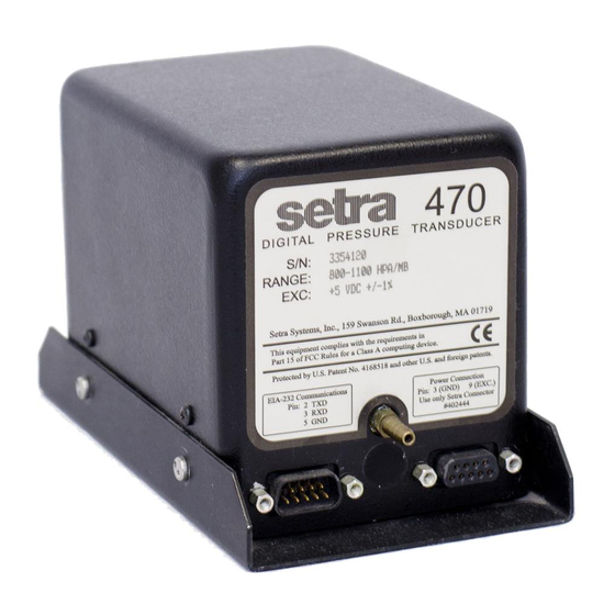
- Page 1 Model 470 Digital Pressure Transducers...
-
Page 2: Table Of Contents
Contents SECTION ONE: Introduction ..................... 3 About the Setra 470 ......................3 About this Manual........................ 4 SECTION TWO: Installing the Model 470 ................. 5 Power Connections ......................5 Pressure Connections ......................5 Communications Hardware ....................5 SECTION THREE: Communications Interfacing ..............7 Communications Software Protocols .................. -
Page 3: Section One: Introduction
The digital design of the Setra 470 provides a simple and reliable communications interface for easy integration into digital control systems. This, in addition to the digital signal processing of the sensing element signal, allows system designers to eliminate the inaccuracies and cost of an analog data acquisition module. -
Page 4: About This Manual
The chapters in the manual are organized to lead you through all the steps required to connect and use a Setra 470. It is unlikely that you will use all of the functions of the Setra 470 in any single application, so select the parts of the manual you need for your application from the following list. -
Page 5: Section Two: Installing The Model 470
Installing the Model 470 Power Connections The Setra 470 requires a 5 volt DC power supply regulated to ±1% which can supply 90 milliamps of current. Use of a correctly rated and regulated power supply is important for correct operation of the digital electronics in the Setra 470. - Page 6 2, and receives on its own pin 3), a “reversing” or “null modem” cable is required for connection. This is simply a cable which connects pin 2 and 3 of the Setra 470 to pins 3 and 2 of the com- puter respectively.
-
Page 7: Section Three: Communications Interfacing
The factory default baud rate of the Setra 470 is 2400. Therefore, the device connected to the Setra 470 initially must also be set to 2400. To change the Setra 470 baud rate refer to Section 5.2. The Setra 470 transmits data as a series of standard ASCII characters, formulated by carriage return and line feed characters. -
Page 8: Functions
Functions This summary of functions is provided for reference only. See the following sections for details on how to use each function. Command codes must be in capital letters. ASCII Function Command ASCII Name Code Code Code Description Section PRINT Report information to a computer or data acquisition system. - Page 9 — — Shuts off the function whose command code follows it. — CLEAR —C 45 67 $2D $43 Turn off MIN/MAX, clear the tare value, convert to the original engineering units. —MIN/MAX —M 45 77 $2D $4D Exit MIN/MAX tracking mode. 4.5 —CONV —U 45 85...
- Page 10 ASCII Function Command ASCII Name Code Code Code Description Section USER Enter conversion ratio for DEFINED non-standard engineering UNITS units in nonvolatile memory. The number 0. The number 1. The number 2. The number 3. The number 4. The number 5. The number 6.
-
Page 11: In Case Of Error Messages
In Case of Error Messages The following summary explains the meaning of error messages that you may receive from the 470 in response to a command, and also tells you what actions to take in response to the error message. -
Page 12: Symbols
Symbols The following summary explains the meaning of symbols that may follow the data you receive from the 470 in response to a command. “OK” The data is within the requirement for the user defined STABILITY INDICATOR. “hPa” The data is reported in hectopascals. -
Page 13: Section Four: Precision Measurement Functions
(ASCII code 10) characters, shown in the example as cr and lf. Converting Engineering Units The Setra 470 measures pressure in almost any engineering units. In addition to the seven built- in pressure conversions and two built-in altitude conversions there is a user definable conversion. -
Page 14: User Defined Engineering Units In Nonvolatile Memory
DISABLE UNITS function (Section 5.3) and omitted the factory default pressure units from the rotation. In this case, on power-up the 470 will report pressure in the next engineering units in the rotation which you have not disabled. -
Page 15: User Defined Engineering Units In Volatile Memory
“ON”. Transmit C, for CLEAR, and restart this procedure from the beginning. 10. If the 470 responds “UNABLE”, the user defined units have been disabled by use of the DISABLE UNITS function (Section 5.3). Transmit C, for CLEAR, re-enable the user defined units (Section 5.3) and restart this procedure from the beginning. -
Page 16: Tracking Min And Max Values
9. If the 470 responds “UNABLE”, the user defined units have been disabled by use of the DISABLE UNITS function (Selection 5.3). Transmit C, for CLEAR, re-enable the user defined units (Section 5.3) and restart this procedure from the beginning. -
Page 17: Setting And Checking Alarm Setpoints In Volatile Memory
The new setpoints being transmitted to the Setra 470 must be in the engineering units currently in use by the Setra 470. The new setpoints must be set within the factory setting of 105% of the pressure range (high setpoint), and 5% below the pressure range (low setpoint). -
Page 18: Repetitive Reporting
3. To add an offset to the reading, transmit -, the minus sign, followed by the amount of the offset, followed by Z, for ZERO. The Setra 470 saves the negative offset as a tare value and subtracts it from every subsequent reading. In response to an interrogation (Section 4.1) the 470 response contains the letter “T”, for Tared Pressure, rather than “A”, absolute pressure. -
Page 19: Digital Altimeter Setting Indicator (Dasi)
To use the DASI function, follow this procedure: 1. Use the CONVERT function (see Section 4.2) so that the 470 reports data in units of pressure in response to an interrogation. (i.e., the transducer should not be reporting in units of altitude.) - Page 20 Or, if the station elevation is 237 meters, transmit: SB237SUS 7. The Setra 470 is now in DASI mode and reports barometric pressure reduced to sea level in response to an INTERROGATION command, indicated by “SEA LEVEL”. 8. To switch from reporting true barometric pressure to corrected sea level pressure and back, transmit B, for SEA LEVEL.
-
Page 21: Section Five: Setup Functions
RS-232C communications port. Devices which are connected this way must be set up to communicate at the same rate of speed. A)To change the baud rate of the Setra 470 from the factory default of 2400, use the following procedure: 1. -
Page 22: Disabling Engineering Units In Nonvolatile Memory
Some applications require you to alternate the engineering units that the data is reported in from one unit to another. To make that more convenient, the Setra 470 can disable one or more of the built-in engineering units accessed by the CONVERT function. This setting is saved until a new one is entered, even if power is shut off and turned back on, unless a new setting is entered into volatile memory using the procedure in Section 5.4. -
Page 23: Disabling Engineering Units In Volatile Memory
CLEAR, to resume operation. Disabling Engineering Units in Volatile Memory As in the previous section, the Setra 470 can disable one or more of the built-in engineering units accessed by the CONVERT function. This function changes the setting in volatile memory only. -
Page 24: Self Diagnostics
(i.e., the transducer should not be reporting in units of altitude.) 2. Set the baud rate of the Setra 470 to 2400. Be sure to follow the procedure to change the baud rate in nonvolatile memory, as in Section 5.2, part B. -
Page 25: Software Revision Number
470. 1. Use the CONVERT function (see Section 4.2) so that the 470 reports data in units of pressure in response to an interrogation. (i.e., the transducer should not be reporting in units of altitude.) - Page 26 To change the Stability Indicator Limit, use the following procedure: 1. Use the CONVERT function (see Section 4.2) so that the 470 reports data in units of pressure in response to an interrogation. (i.e., the transducer should not be reporting in units of altitude.)
-
Page 27: Section Six: Altitude Measurement Functions
SECTION SIX Altitude Measurement Functions The Setra 470 Digital Pressure Transducer can report a variety of altitude measurements. It may be used as an altimeter calibrator, a standard altimeter, a true corrected altimeter (self corrected or remote), or as a relative altimeter. It may also be used to indicate small relative changes in altitude through the use of the zero/tare function. - Page 28 B) If you don’t know the station elevation, use this procedure to report true altitude. 1. Use the CONVERT function (see Section 4.2) so that the 470 reports data in units of pressure in response to an interrogation. (i.e., the transducer should not be reporting in units of altitude.)
-
Page 29: Relative Altitude Measurement
Relative Altitude Measurement The Setra 470 can measure relative altitude in either Standard or True Altimeter Mode. In this mode, the 470 reports altitude relative to a reference altitude which you establish by setting the reported altitude reading to zero, or by offsetting it to a higher or lower value by a specified amount. -
Page 30: Section Seven: Calibration
“ON”. The procedures which require this refer you to this section of the manual. a) If the enable switch is set to “ON’ before the power is applied to the 470, after its internal power-up sequence it responds “PROTEC” rather than with its normal verify message. -
Page 31: Zero Calibration
3. Set the program enable switch to “ON” (Section 7.2). 4. Transmit SZ, for SETUP ZERO. 5. If the 470 responds “NO CAL”, the program enable switch in Step 3 is not set. Transmit C, for CLEAR, and restart this procedure. -
Page 32: Span Calibration
Span Calibration To perform the span calibration on the 470, it is necessary to apply both the zero and the full scale pressures, as described in the following procedure. This procedure can be aborted at any point by setting the program enable switch to “OFF” and transmitting C, to execute the CLEAR function. -
Page 33: Interface Program Example
DS (data set ready) parameters, and that the RS parameter is used to suppress the request to send signal. This is done because the Setra 470 implements a very simple subset of the RS-232 standard and does not support these handshaking signals. -
Page 34: Specifications
Notes: Accuracy as RSS of non-linearity, hysteresis, and non-repeatability. Unit calibrated at 70°F. Maximum thermal error is computed from this datum. Information about the Model 470 Digital Pressure Transducer contained in this document is subject to change without notice. -
Page 35: Limited Warranty
Limited Warranty SETRA warrants its products to be free from defects in materials and workmanship, subject to the folloing terms and conditions: Without charge, SETRA will repair or replace products found to be defective in materials or workmanship within the warranty period; provided that: the product has not been subjected to abuse, neglect, accident, incorrect wiring not our own, improper installation or servicing, or use in violation of instructions furnished by SETRA;...
Need help?
Do you have a question about the 470 and is the answer not in the manual?
Questions and answers