Advertisement
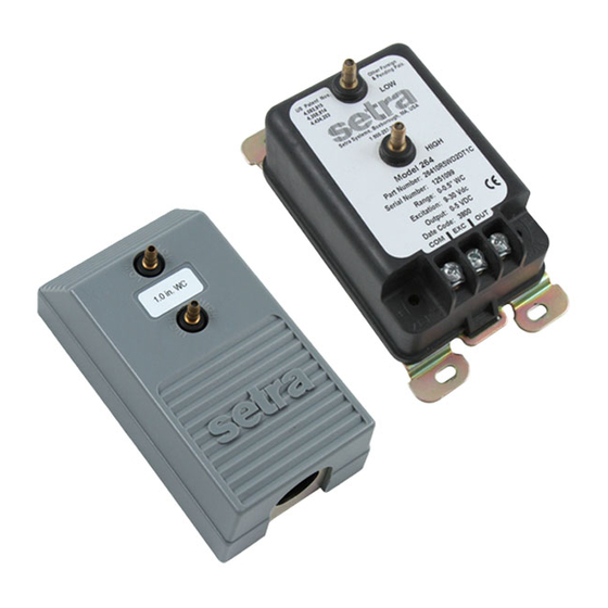
DPT 264 Series Low Pressure Transducers and Transmitters
1.0 GENERAL INFORMATION
Every Model DPT264 has been tested and calibrated before shipment. Specific performance specifications are
shown on page 3 of this Guide.
Setra Systems DPT264 pressure transducers sense differential or gage (static) pressure and convert this pressure
difference to a proportional high level analog output for both unidirectional and bi-directional pressure ranges.
Two standard output versions are offered: A voltage output of 0 to 5 VDC or a current output of 4 to 20 mA.
2.0 MECHANICAL INSTALLATION
2.1Media Compatibility
Model DPT264 transducers are designed to be used with air or non-conducting gases. Use with liquids or
corrosive gases will dame the unit.
2.2 Environment
The operating temperature limits of the DPT264 are 0°F to +175°F (-18°C to +79°C)
The compensated temperature range is 0°F to +150°F (-18°C to +65°C).
2.3 Mounting
The DPT264 series is designed for mounting in either 2.75: snap-track or by using the four (4)
slots (suitable for #6 screws) that are provided on the plate. Optimum performance is obtained by isolating
the instrument from vibration and providing relatively clean, dry ambient air to the pressure ports.
Even though there is no flow through the DPT264, a filter is located in both the high and low-pressure ports
for use in extreme dust or moisture conditions.
In most cases, preferred installation is with the baseplate mounted vertically and located on a relatively flat
surface in a junction box or attached to a nearby beam. Easy field replacement is possible by removing
the single case screw that holds the black sensor/circuit housing to the baseplate and lifting the black
housing free. The baseplate remains mounted and can be used with the replacement unit's black
sensor/circuit housing.
The axis most sensitive to vibration is the one perpendicular to the baseplate. Avoid mounting with
maximum vibration along this axis.
2.4 Pressure Fittings
The Model DPT264 is designed to be used with 3/16" I.D. push-on tubing. Both the positive (high) pressure
port and the reference (low) pressure port are located on the front of the unit, labeled "HIGH" and "LOW"
respectively. For best results (shortest response time), 3/16" I.D. tubing is suggested for tubing lengths up to
100 feet long, 1/4" I.D. for tubing lengths up to 300 feet, and 3/8" I.D. for tubing lengths up to 900 feet.
3.0 ELECTRICAL INSTALLATION
If the Model DPT264 is supplied with the optional Conduit Enclosure, access the electrical terminations by
removing the cover.
3.1 Voltage Output Units
The Model DPT264 voltage output is a 3-wire circuit, with three terminals available for wiring. These
terminals have the designation COM, EXC, and OUT (see Diagram 1). The power supply and signal
references are commoned on the circuit (see Diagram 2). The DPT264 voltage output can operate from 9-
30 VDC excitation. The DPT264 has a 0-5 VDC output.
Setra Systems
Installation Guide
Advertisement
Table of Contents

Related Manuals for Setra Systems DPT264 Series


Summary of Contents for Setra Systems DPT264 Series
- Page 1 The compensated temperature range is 0°F to +150°F (-18°C to +65°C). 2.3 Mounting The DPT264 series is designed for mounting in either 2.75: snap-track or by using the four (4) slots (suitable for #6 screws) that are provided on the plate. Optimum performance is obtained by isolating the instrument from vibration and providing relatively clean, dry ambient air to the pressure ports.
- Page 2 Voltage Circuit Diagram Readout Model DPT264 Power Supply Diagram 1 Diagram 2 +EXC Connect to positive terminal of 9-30 VDC Power Supply +OUT Connect to positive terminal of Control or Pressure Monitor Connect as the reference for power supply and output signal 3.2 Current Output Units The Model DPT264 is a two-wire loop-powered 4 to 20 mA current output unit and delivers rated current into any external load of 0 to 800 ohms.
- Page 3 4.1 Voltage Output Zero Adjustment While monitoring the voltage between the positive output (OUT) and common (COM), and with both pressure ports open to atmosphere, the zero may be adjusted by turning the zero adjustment screw (see Diagram 1 for location of the zero adjustment). For 0-5 VDC output units, the factory settings are 0.050 VDC (±50 mV) for unidirectional pressure ranges and 2.5 VDC (±50 mV) for bi-directional pressure ranges.
- Page 4 Please contact Setra (800-257-3872, 978-263-1400) before returning unit for repair to review information relative to your application. Many times only minor field adjustments may be necessary. When returning a product to Setra, the material should be carefully packaged and shipped prepaid to: Setra Systems, Inc. 159 Swanson Road Boxborough, MA 01719...
Need help?
Do you have a question about the DPT264 Series and is the answer not in the manual?
Questions and answers