
Related Manuals for Setra Systems 267


Summary of Contents for Setra Systems 267
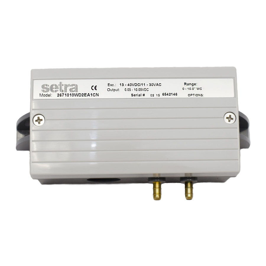
- Page 1 Model 267 & 267MR Operating Instructions Setra Systems, Inc. 159 Swanson Road, Boxborough, MA 01719 800.257.3872 • www.setra.com...
-
Page 2: General Information
0 to 5 VDC or 0 to 10 VDC, and a current output of 4 to 20 mA. Sections 1 through 4 and 7 through 9 of this guide apply to both models 267 and 267MR. Section 5 refers to the model 267 only. Section 6 refers to the model 267MR only. -
Page 3: Electrical Installation
The 267MR has a field selectable 0-5 or 0-10 VDC output. (See section 6.0 for switch settings to determine whether the voltage output is set to 0-5 or 0-10 VDC). The 267 has either a 0-5 or 0-10 output, calibrated at the factory. - Page 4 1/2’’ conduit opening, PG9 or PG-13.5 electrical termination The model 267 and 267MR is a two-wire loop-powered 4 to 20mA current output unit (see diagram 5). The current flows into +EXC terminal and returns back to the power supply through the -EXC terminal (see diagram 6).
- Page 5 3.4 Current output units: 9 pin D-sub connector electrical termination The model 267 and 267MR is a two-wired loop-powered 4 to 20mA current output unit (see diagram 6). The current flows into +EXC. Pin 4 (+EXC) and return to the power supply through pin 9 (-EXC) (see diagram 7).
- Page 6 4.0 Calibration The 267 and 267MR transducer is factory calibrated and should require no field adjustment. Generally, the mounting position will have a zero shift effect on ranges below 1” WC. Whenever possible, any zero and/or span offsets should be corrected by software adjustment in the user’s control system.
- Page 7 (electronic manometer, digital pressure gauge, ect.) with at least comparable accuracy to the 267 or 267MR transducer (<±1% FS). With full range pressure applied to the high pressure port (reference port open to atmosphere), the span maybe adjusted by turning the SPAN adjustment screw.
- Page 8 5.0 Model 267 optional LCD display The model 267 is available with an optional 3 1/2 digit LCD display. The LCD display is adjusted at the factory prior to shipment. The LDC is connected to the zero and span adjustment potentiometers.
- Page 9 Table 1: Range switching instructions for inches of water column NOTE: Black square in diagram indicates switch position. Switch settings Switch settings Switch settings range range range range 0-5V output 0-10V output 4-20MA output Factory default setting 0-0.1” 0-1” 0-5” 0-30”...
-
Page 10: General Specifications
7.0 Model 267 & 267MR performance specifications General specifications Accuracy RSS* (at constant temperature ±1.0% FS Non-linearity, BFSL ±0.98 FS Hysteresis ±0.2% FS Non-repeatability ±0.1% FS Compensated temperature range 40° to 150°F (5° to 65° C) Zero/span shift, %FS/°F(°C) 0.033 (0.06) -
Page 11: Returning Products For Repair
Many times only minor field adjustments may be necessary. When returning a product to Setra, the material should be carefully packaged and shipped prepaid to: Setra Systems, Inc. 159 Swanson Road Boxborough, MA 01719-1304... - Page 12 No representative or person is authorized to give any warranty other than as set out above or to assume for Setra any other liability in connection with the sale of its products. Setra Systems, Inc. 159 Swanson Road, Boxborough, MA 01719...
Need help?
Do you have a question about the 267 and is the answer not in the manual?
Questions and answers