
Related Manuals for Setra Systems 231RS


Summary of Contents for Setra Systems 231RS
- Page 1 Model 231RS Operating Instructions Setra Systems, Inc. 159 Swanson Road, Boxborough, MA 01719 800.257.3872 • www.setra.com...
-
Page 2: Table Of Contents
Table of Contents 1.0 General information ....................... 3 2.0 Mechanical installation ....................4 2.1 Media compatibility ....................4 2.2 Environment ....................... 4 ..2.3.Pressure.fitting ......................4 2.4 Mounting ........................4 2.5 Installation procedures ..................... 4 3.0 Electrical installation ..................... 7 3.1 Electrical termination Wiring: 2-wire, 4 to 20 mA, and Remote zero ............ -
Page 3: General Information
231RS range code you selected when you purchased the 231RS. See Range Codes in table below. (Range codes also listed on inside of housing cover). -
Page 4: Mechanical Installation
1/2” I.D. conduit connection. This opening must be sealed according to standard industry practices in order to prevent moisture ingress into the Model 231RS. 2.4 Mounting The Model 231RS can be easily mounted using the two mounting screws located on the side of the unit. 2.5 Installation procedures... - Page 5 Valve B High Valve A = High side valve Valve B = Low side valve Valves not included. Pipe Pipe Figure 1 Model 231RS (Conduit version, P/N: 231GRSX3MXXX) - Outline drawing (152.4) 5.56 (141.2) R 0.1 (2.5) 0.35 (50.8) Front view 1.98...
- Page 6 Model 231RS (Cable version, P/N: 231GRSX4MXXX) Model 231RS (Armored Cable Version, P/N: 231GRSXAJXXX) Outline Drawing (152.4) 5.56 (141.2) R 0.1 (2.5) 0.35 (8.8) (50.8) 1.22 1.66 (31) (42.2) Front view 1.98 (50.3) (10.2) 4.87 (123.6) 5.08 (129) Side view 1.56 0.95...
-
Page 7: Electrical Installation
Wiring: 2-Wire - 4 to 20 mA (Current Output) and Remote Zero Model 231RS when configured as a current output transducer is a true 2-wire, 4-20 mA current output device and delivers rated current into any external load of 0-250 ohms. -
Page 8: Electrical Terminations
Wiring: 3-Wire, 0 to 5, 0 to 10, 1-5 VDC and Remote Zero Model 231RS when configured for voltage output is a 3-wire circuit device with three terminals available for wiring. The -Excitation and -Output are commoned on the circuit. -
Page 9: Remote Sensors Installation
5. Fit conduit into conduit fitting, and tighten conduit watertight strain relief. To connect the wires from the remote sensor to the unit, remove the terminal blocks from the circuit board and use the following chart: Installation of the Model 231RS is now complete. - Page 10 1/2 inch conduit opening Terminal block Conduit adapter 1.40 (35.48) (GND) (+OUT) (mm) (COM) 3.61 (+EXC) (91.74) 3/4” HEX Chart 1. Electrical wiring chart for High & Low Pressure Sensors (Conduit version) 1.62 1.68 1/4” NPT CAUTION: (41.22) (42.57) Reverse excitation will permanently damage unit.
- Page 11 3.3 Remote sensors installation Cable Version (P/N: 231GRSX4MXXXX) For cable version remote sensors, use the following instructions: 1. Install the remote sensors into the system plumbing (use 3/4” hex to tighten”) Important: Each remote sensor is labeled “HIGH PRESSURE SENSOR” or “LOW PRESSURE SENSOR”, respectively.
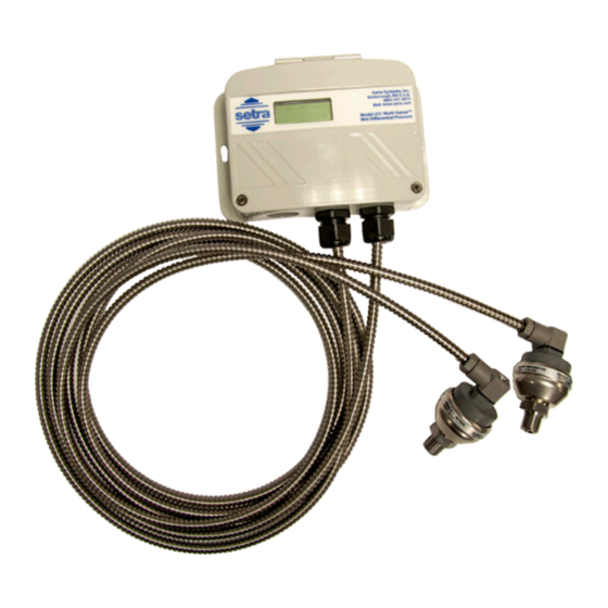
- Page 12 3.3 Remote Sensors Installation Armored Cable Version (P/N: 231GRSXAJXXXX) For Armored Cable version remote sensors, use the following instructions: 1. Install the remote sensors into the system plumbing (use 3/4” hex to tighten”) Important: Each remote sensor is labeled “HIGH PRESSURE SENSOR” or “LOW PRESSURE SENSOR”, respectively.
-
Page 13: Configurations
Range selection switch: The unit is set to the highest range when calibrated at the factory. To select the other ranges, slide the switch to the right. Important: Push “zero” button after installing the Model 231RS, and after changing range. Auto zero button: Press and hold the “ZERO” push-button for 2 seconds to automatically reset zero or provide contact closure on “Remote Zero, see figure 4 and figure 5. -
Page 14: Return Products For Repair
Many times only minor field adjustments may be necessary. When returning a product to Setra, the material should be carefully packaged and shipped prepaid to: Setra Systems, Inc. 159 Swanson Road Boxborough, MA 01719-1304... -
Page 15: Warranty & Limitation Of Liability
SETRA any other liability in connection with the sale of its products. For all CE technical questions, contact Setra Systems, USA. EU customers may contact our EU representative Hengstler GmbH, Uhlandstr 49, 78554 Aldingen, Germany (Tel: +49-7424-... - Page 16 Setra Systems, Inc. 159 Swanson Road, Boxborough, MA 01719 800.257.3872 • www.setra.com...
Need help?
Do you have a question about the 231RS and is the answer not in the manual?
Questions and answers