Table of Contents
Advertisement
Quick Links
1.0 GENERAL INFORMATION
Every Model 264 has been tested and calibrated before shipment. Specific
performance specifications are shown on page 3 of this Guide.
Setra Systems 264 pressure transducers sense differential or gauge (static) pres-
sure and convert this pressure difference to a proportional high level analog
output for both unidirectional and bidirectional pressure ranges. Two standard
output versions are offered: A voltage output of 0 to 5 VDC or a current output
of 4 to 20 mA.
2.0 MECHANICAL INSTALLATION
2.1 Media Compatibility
Model 264 transducers are designed to be used with air or nonconducting
gases. Use with liquids or corrosive gases will damage the unit.
2.2 Environment
The operating temperature limits of the 264 are 0°F to +175°F (-18°C to +79°C).
The compensated temperature range is 0°F to +150°F (-18°C to +65°C).
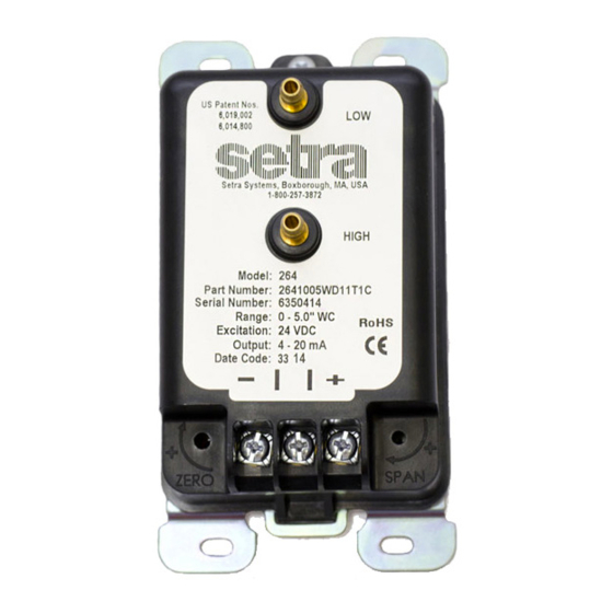
2.3 Pressure Fittings
The Model 264 is designed to be used with 3/16" I.D. push-on tubing. Both the
positive (high) pressure port and the reference (low) pressure port are located
on the front of the unit, labeled "HIGH" and "LOW" respectively. For best
results (shortest response times), 3/16" I.D. tubing is suggested for tubing
lengths up to 100 feet long, 1/4" I.D. for tubing lengths up to 300 feet, and 3/8"
I.D. for tubing lengths up to 900 feet.
3.0 ELECTRICAL INSTALLATION
If the Model 264 is supplied with the optional Conduit Enclosure, access the
electrical terminations by removing the cover. The output of 0 to 5 VDC or
4 to 20 mA is designated by specific Code numbers in the configurable part
number; i.e., 2641xxxxx 11xx x, where 11 designates the 4 to 20 mA output;
2641xxxxx 2Dxx x, where 2D designates the 0 to 5 VDC output. The output is
also shown on the 264 label.
For CE Compliance, a shielded cable with both ends properly grounded is
required.
3.1 Voltage Output Units
The Model 264 voltage output is a 3-wire circuit, with three terminals
available for wiring. These terminals have the designation COM, EXC and OUT
(See Diagram 1). The power supply and signal references are commoned on
the circuit (See Diagram 2). The 264 voltage output can operate from 9-30 VDC
excitation. The 264 has a 0 - 5 VDC output.
Installation Guide
Setra Systems Model 264
Differential Pressure Transducer
Advertisement
Table of Contents

Related Manuals for Setra Systems 264


Summary of Contents for Setra Systems 264
-
Page 1: General Information
The compensated temperature range is 0°F to +150°F (-18°C to +65°C). 2.3 Pressure Fittings The Model 264 is designed to be used with 3/16” I.D. push-on tubing. Both the positive (high) pressure port and the reference (low) pressure port are located on the front of the unit, labeled “HIGH”... - Page 2 3.2 Current Output Units The Model 264 is a two-wire loop-powered 4 to 20mA current output unit and delivers rated current into any external load of 0 to 800 ohms. These terminals have the designation of + and - (See Diagram 3). The current flows into the + terminal and returns back to the power supply through the - terminal (See Diagram 4).
- Page 3 Span or full scale output adjustments should only be performed by using an accurate pressure standard (electronic manometer, digital pressure gauge, etc.), with at least comparable accuracy to the 264 transducer (±1% FS). With full range pressure applied to the high pressure port (reference port open to atmo- sphere), the span may be adjusted by turning the SPAN adjustment screw.
- Page 4 257-3872 (978-263-1400) for scheduling. 7.0 WARRANTY AND LIMITATION OF LIABILITY SETRA warrants its Model 264 products to the original consumer purchaser against defects for a period of three years from the date of sale by SETRA, as shown in its shipping documents.
Need help?
Do you have a question about the 264 and is the answer not in the manual?
Questions and answers