
Related Manuals for Setra Systems 267


Summary of Contents for Setra Systems 267
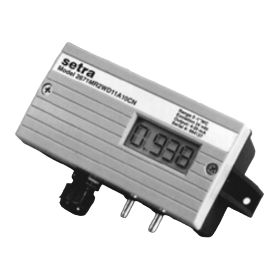
- Page 1 Installation Guide Model 267 and 267MR Differential Pressure Transducers 1-800-257-3872 Toll Free 1-978-264-0292 Fax www.setra.com Web Site 159 Swanson Road, Boxborough, MA 01719-1304 Tel: 800-257-3872/978-263-1400...
- Page 2 10.2 Replacing the Desiccating Cover HVAC Products To ensure the uninterrupted system operation, replacement covers with desic- cant are available. Contact your local representative or Setra Systems’ customer service department at (800) 257-3872 to order. Model 264 For Static Duct and Flow...
-
Page 3: Returning Products For Repair
SETRA any other liability in connection with the sale of its products. 10.2 Replacing the Desiccating Cover .............. 11 For all CE technical questions, contact Setra Systems, USA. EU customers may contact our EU representative Hengstler GmbH, Uhlandstr. 49, 78554 Aldingen, Germany (Tel: +49-7424-890, Fax: +49-7424-89500). - Page 4 625Pa 1875Pa ± ± ± ± 25Pa 125Pa 312Pa 937Pa 7.0 MODEL 267 & 267MR PERFORMANCE SPECIFICATIONS Accuracy RSS (at constant temperature.) ±1.0% FS Non-Linearity, BFSL ±0.98% FS Hysteresis 0.2% FS Non-Repeatability 0.1% FS *RSS of Non-Linearity, Non-Repeatability and Hysteresis.
-
Page 5: General Information
The 4-20 mA current version has only 4 switches. Sections 1 through 4 and 7 through 9 of this Guide apply to both Models 267 and 267MR. Section 5 refers to the Model 267 only. Section 6 refers to the TABLE-1 RANGE SWITCHING INSTRUCTIONS FOR IN.WC... -
Page 6: Mechanical Installation
3.1 Voltage Output Units - 1/2” Conduit Opening, PG9 or PG-13.5 Elec- trical Termination The Model 267 is available with an optional 3 1/2 digit LCD display. The LCD display Wiring terminations are identified on the circuit board below the terminal strip is adjusted at the factory prior to shipment. - Page 7 0-5 or 0-10 Unidirectional Pressure Ranges Bidirectional Pressure Ranges VDC.) The 267 has either a 0-5 VDC or 0-10 VDC output, calibrated at the Fac- Zero Adjustment Output Zero Adjustment Output tory.
- Page 8 3.4 Current Output Untis – 9 pin D-sub Connector Electrical Termination The Model 267 and 267MR voltage output is a 3-wire circuit, with three pins avail- The Model 267 and 267MR is a two-wire loop-powered 4 to 20mA current out- able for wiring (see Diagram 3).
Need help?
Do you have a question about the 267 and is the answer not in the manual?
Questions and answers