Advertisement
Quick Links
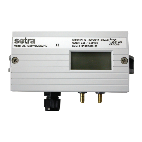
DPT267 and DPT267MR Series Low Pressure Transducers
1. GENERAL INFORMATION
Every Model 267 and Model 267MR (Multi-Range) has been tested and calibrated before shipment.
Specific performance specifications are listed on Page 9 of this Guide.
The Model 267 is single range only. The Model 267MR has field selectable range capability. The
267MR is factory calibrated for the highest pressure range. The range label on the cover of the unit
indicates the factory-calibrated range. Should the 267MR be re-ranged in the field, the Multi-Range
labels are included.
Setra Systems 267 and 267MR pressure transducers sense differential or gauge (static) pressure and
convert this pressure difference to a proportional high level analog output for both unidirectional and
bidirectional pressure ranges. Two output versions are offered: A voltage output, configurable: 0 to 5
VDC or 0 to 10 VDC, and a current output: 4 to 20 mA
Sections 1 through 4 and 7 through 9 of this Guide apply to both Model 267 and 267MR. Section 5
refers to the Model 267 only. Section 6 refers to the Model 267MR only.
2.0 MECHANICAL INSTALLATION
2.1 Media Compatibility
Model 267 and 267MR transducers are designed to be used with air or non-conducting gases.
Use with liquids or corrosive gases will damage the unit.
2.2 Environment
The operating temperature limits of the 267 and 267MR are as follows:
Operating Temperature
Compensated Temperature Range +40°F to +150°F (+5°C to +65°C)
2.3 Pressure Fittings
The Model 267 and 267MR can be supplied with three different pressure fitting configurations:
1. 3/16" O.D. Barbed Brass Pressure Fittings – Typically installed with 1/4" push-on tubing.
2. 1/4" NPT Brass Pressure Fittings – Typically installed with mating NPT male fitting.
3. Static Pressure Probe – Installed on the duct by drilling a 7/16" hole in the duct at the desired
mounting location, inserting the pressure probe into the duct, and mounting the 267 onto the duct
with the mounting tabs.
For the 3/16" O.D. and 1/4" NPT pressure fittings, both the positive (high) pressure port and the
reference (low) pressure port are located on the bottom of the unit, labeled "HIGH" and "LOW"
respectively. For best results (shortest response times), 3/16" I.D. tubing is suggested for tubing
lengths up to 100 feet long, 1/4" I.D. for tubing lengths up to 300 feet, and 3/8" I.D. for tubing lengths
up to 900 feet.
The static pressure probe is the positive (high) pressure port located on the back of the unit. The
reference (low) pressure port is located on the bottom of the unit and can be used for differential pressure
measurements.
3.0 ELECTRICAL INSTALLATION
Wiring is through a 1/2" conduit opening or an optional PG-9 or PG-13-5 or 9-pin D-sub connector. (See
Section 3.2 for instructions on wiring the 9 pin D-sub connector.) Both current and voltage output units are
reverse wiring protected.
Setra Systems
Operating Instructions
0°F to +150°F (-18°C to +65°C)
Advertisement

Related Manuals for Setra Systems DPT267 Series


Summary of Contents for Setra Systems DPT267 Series
- Page 1 Should the 267MR be re-ranged in the field, the Multi-Range labels are included. Setra Systems 267 and 267MR pressure transducers sense differential or gauge (static) pressure and convert this pressure difference to a proportional high level analog output for both unidirectional and bidirectional pressure ranges.
- Page 2 3.1 Voltage Output Units – 1/2” Conduit Opening, PG-9 or PG-13.5 Electrical Termination Wiring terminations are identified on the circuti board below the terminal strip (see Section 3.1 for voltage output units or Section 3.3 for current units). To access the terminal strip, turn the screws on top of the case counter clockwise until the cover can be removed.
- Page 3 Voltage Output Units – 9 pin D-sub Connector Electrical Termination The Model 267 and 267MR voltage output is a 3-wire circuit with three pins available for wiring (see Diagram 3). The voltage output pin designations are shows in Diagram 4. Diagram 4 PIN 4 CONNECTION...
- Page 4 3.4 Current Output Units – 9 pin D-sub Connector electrical Termination The Model 267 and 267MR is a two wire loop-powered 4 to 20 mA current output unit (see Diagram 6). The current flows into +EXC. Pin4 (+EXC.) and returns back to the power supply through Pin 9 (-EXC) (see Diagram 7).
- Page 5 3.6 EMC Certification This product complies with EN61326 Electrical Equipment for Measurement Control and Laboratory use – EMC Requirements for Minimum Requirements and Industrial Locations. Special caution should be taken to meet Standard EN61000-4-5: 1995 Surge Immunity if any of the following conditions apply to the installation: the product is installed outside;...
- Page 6 4.3 Current Output Zero Adjustment While monitoring the current output, and with both pressure ports open to atmosphere, the zero may be adjusted by turning the zero adjustment screw. (See Diagram 5 for location of zero adjustment.) Factory settings are: Unidirectional Pressure Ranges Bidirectional Pressure Ranges Zero Adjustment...
- Page 7 TABLE 1 RANGE SWITCHING INSTRUCTIONS FOR IN.WC Factory Default Setting 7.0 MODEL 267 & 267MR PERFORMANCE SPECIFICATIONS Accuracy RSS* (at constant temperature) ±1.0% FS Non-Linearity, BFSL ±0.98% FS Hysteresis 0.2% FS Non-Repeatability 0.1% FS *RSS of Non-Linearity, Non-Repeatability, and Hyseresis Thermal Effects Compensated Range °F (°C) +40 to +150 (+5 to +65...
Need help?
Do you have a question about the DPT267 Series and is the answer not in the manual?
Questions and answers