Table of Contents
Advertisement
Advertisement
Table of Contents

Related Manuals for Setra Systems 230


Summary of Contents for Setra Systems 230
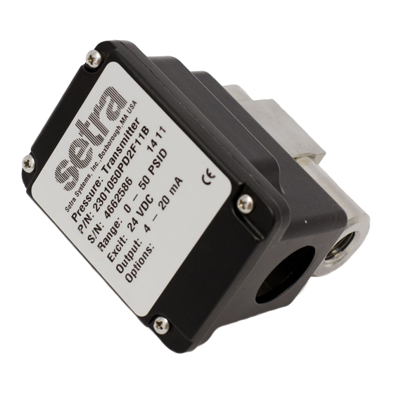
- Page 1 Installation Guide Model 230 Wet/Wet Differential Pressure Transducer...
-
Page 2: Table Of Contents
Table of Contents 1.0 General InformatIon ......... 3 2.0 mechanIcal InstallatIons ....... 3 2.1 media compatibility ..........3 2.2 environment ............. 3 2.3 Pressure fittings ............3 2.4 moisture Precautions ..........3 2.5 mounting ..............3 2.6 Installation Procedures .......... 4 2.7 Bleeding the Pressure Ports ........ -
Page 3: General Information
2.5 mounting The Model 230 is supplied with a mounting bracket and two 6-32 x 3/8 hex head screws. Attach bracket to mounting loca- tion first, using holes or band clamp notches available on large section of the bracket. Attach transducer to bracket by using... -
Page 4: Installation Procedures
2.6 Installation Procedures High Valve A Valve B If the Model 230 is supplied with an optional 3-valve or 5 valve Valve C manifold assembly, refer to Section 2.8 and 2.9. Optional 3-Valve and 5-Valve Manifold Assembly Procedure, for further installation High procedures. -
Page 5: Optional 3-Valve Manifold Procedure
5. Close the bleed screws on the Model 230 6. Close V3. To take the 230 out of service: 1. Open V3 to equalize the pressure at the Model 230. 2. Close the V1 and V2. 3. Open the bleed screws on the Model 230. -
Page 6: Optional 5-Valve Manifold Procedure
3. High Pressure Side: Slowly open V4 to bleed the air out of the high pressure side, close V4 when air stops bleeding. Open the 2 bleed screws on the high pressure side of the Model 230, see Sec. 2.7, paragraph 1. -
Page 7: Electrical Installation
Input Power The 230 can operate from either 9-30 VDC for 0-5 VDC output version or 13-30 VDC for 0-10 VDC output version Excitation Connected to positive terminal of DC Power Supply Connect as the reference for power supply and output signal Connect to positive terminal of Control or Pressure Monitor 3.2 current output Units... -
Page 8: Calibration
However, zero and span adjustments are made by removing the cover on the top of the 230 and the 6-32 seal screws in the plastic terminal block. Be sure to reinstall seal screws after zero and/or span adjustments. -
Page 9: Current Output Zero Adjustment
Allow approximately 3 weeks after receipt at Setra Systems for the repair and return of the unit. Non-warran- ty repairs will not be made without customer approval and purchase order to cover repair charges. -
Page 10: Limited Warranty And Limitation Of Liability
6.0 LIMITED WARRANTY AND LIMITATION OF LIABILITY SETRA warrants its products to be free from defects in materials and workmanship, subject to the following terms and conditions: Without charge, SETRA will repair or replace products found to be defective in materials or workmanship within the warranty period;...
Need help?
Do you have a question about the 230 and is the answer not in the manual?
Questions and answers