Table of Contents
Advertisement
Quick Links
Advertisement
Chapters
Table of Contents

Related Manuals for HYDAC FILTER SYSTEMS OLFP-3 Series


Summary of Contents for HYDAC FILTER SYSTEMS OLFP-3 Series
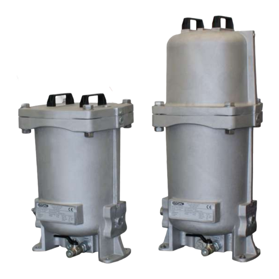
- Page 1 OLFP-3 / OLFP-6 OffLine Filter Pressure Installation and Maintenance Instructions English • (translation of original instructions) Document No. : 3819798a • 4/7/2020 Follow these instructions for proper and safe use. Keep for future reference.
-
Page 2: Table Of Contents
Table of Contents HYDAC FILTER SYSTEMS GMBH Table of Contents 1 General ........................ 4 Imprint ...................... 4 Documentation Representative................ 4 Purpose of this manual .................. 5 Target group of the manual................ 5 Illustrations in the manual ................ 6 1.5.1 Illustration on the title page.............. 6 1.5.2... - Page 3 HYDAC FILTER SYSTEMS GMBH Table of Contents Components.................... 30 4 Transportation/storage .................... 32 5 Mounting/installing .................... 34 Fastening/mounting the filter housing ............ 34 Avoiding siphoning .................. 37 Observing/calculating pressure loss .............. 39 Measuring or displaying the back pressure / differential pressure .... 41 Connecting the electrical clogging indicator...........
-
Page 4: General
1 | General HYDAC FILTER SYSTEMS GMBH 1 General In this chapter, you will find helpful notes on handling these in- structions. 1.1 Imprint Manufacturer / publisher and responsible for the content: Address of the manufacturer Contact address HYDAC FILTER SYSTEMS... -
Page 5: Purpose Of This Manual
HYDAC FILTER SYSTEMS GMBH General | 1 1.3 Purpose of this manual Before you use this product for the first time or if you have been asked to carry out other work on the product, please read this manual. The use and the handling of the product described in the fol-... -
Page 6: Illustrations In The Manual
1 | General HYDAC FILTER SYSTEMS GMBH 1.5 Illustrations in the manual You will find illustrations in this manual. You can find details re- garding these in the following chapters. 1.5.1 Illustration on the title page You will find the following information on the title page of this... -
Page 7: Representation Of Requirements
HYDAC FILTER SYSTEMS GMBH General | 1 Please note that you can directly access information through the directories. However, this does not release you from the obligation to read this manual fully before commissioning. The document no. with the index (4) is meant for identifying and reordering the manual. -
Page 8: Representation Of Intermediate Results/Results
1 | General HYDAC FILTER SYSTEMS GMBH Procedural instructions with a random sequence Procedural instructions that have a random sequence are listed as bullet points (-). An example of a procedural instruction with a random se- quence: – Clean the display. -
Page 9: Representation Of Warning/General Safety Information
HYDAC FILTER SYSTEMS GMBH General | 1 1.5.5 Representation of warning/general safety information All the warning / general safety information in this manual are highlighted with pictograms and signal words. The pictogram and the signal word give you an indication of the severity of the danger. -
Page 10: Signal Words And Their Meaning In The General Safety Information
1 | General HYDAC FILTER SYSTEMS GMBH 1.5.6 Signal words and their meaning in the general safety information In these instructions you will find the following signal words: DANGER DANGER – The signal word indicates a hazardous situation with a high level of risk, which, if not avoided, will result lethal or serious injury. -
Page 11: Hazard Symbols / Pictograms
HYDAC FILTER SYSTEMS GMBH General | 1 1.6 Hazard symbols / pictograms The following are the safety symbols / pictograms in this man- ual. They indicate specific dangers to persons, property or to the environment. Observe these safety symbols / pictograms and act with particular caution in such cases. -
Page 12: Supplementary Symbols
1 | General HYDAC FILTER SYSTEMS GMBH Exposed electrical components Danger due to operating pressure Signs used for the required specialist personnel These symbols show the required training/knowledge for in- stallation work and/or maintenance work. Specialist personnel - Electrician Such persons have specific specialist training and several years' work experience. -
Page 13: Exclusion Of Liability/Warranty
HYDAC FILTER SYSTEMS GMBH General | 1 Required tools 1.8 Exclusion of liability/warranty For the warranty provided by us, please refer to the Terms of Delivery. They are made available to you at the conclusion of the contract at the latest. You will also find these under www.hydac.com ->... -
Page 14: Validity Of This Manual
1 | General HYDAC FILTER SYSTEMS GMBH 1.10 Validity of this manual The diagrams and visualizations in this manual are meant for general illustration purposes. Therefore, representations and functional options can deviate from the delivered product. We reserve the right to changes to the contents of this manual without prior notice. -
Page 15: Safety Information
HYDAC FILTER SYSTEMS GMBH Safety information | 2 2 Safety information The General Safety Information provides important information on handling the device. A prerequisite for safe work is the maintenance of all stated General Safety Instructions and pre- cautions. In addition, the local accident prevention specifica- tions and general safety regulations that apply for the area of operation of the device must be observed. - Page 16 2 | Safety information HYDAC FILTER SYSTEMS GMBH NOTICE Overpressure The filter unit will be damaged/destroyed u Observe the permissible pressure at the suction port (IN). NOTICE Siphoning effect Reservoir overflowing/leaking = oil spill u Remove the ends of the hoses from the reservoir after op- eration or shut the shut-off device in the suction line.
- Page 17 HYDAC FILTER SYSTEMS GMBH Safety information | 2 NOTICE Do not grip the filter unit/filter housing at the clogging indicator The clogging indicator will be damaged/destroyed. u Grip the filter unit/filter housing with your hands on the fil- ter housing to transport or to store it.
-
Page 18: Filter Housing Overview
3 | Filter housing overview HYDAC FILTER SYSTEMS GMBH 3 Filter housing overview The OffLine Filter Pressure OLFP is a stationary bypass filter and is meant for the removal of oil degradation products, water and solid particles from hydraulic and lubricating fluids. Due to its compact construction, the OLFP is also ideally suited for use in even the smallest of installation spaces. -
Page 19: Proper/Designated Use
HYDAC FILTER SYSTEMS GMBH Filter housing overview | 3 3.1 Proper/designated use Use the filter housing only for the application described in the following: The OffLine Filter Pressure OLFP is a stationary bypass filter and is meant for the removal of oil degradation products, water and solid particles from hydraulic and lubricating fluids. -
Page 20: Improper Use Or Use Deviating From Intended Use
3 | Filter housing overview HYDAC FILTER SYSTEMS GMBH 3.2 Improper Use or Use Deviating from Intended Use DANGER Danger due to unintended use Bodily injury and damage to property u Never operate the filter unit in potentially explosive atmos- pheres. -
Page 21: Checking The Scope Of Delivery
HYDAC FILTER SYSTEMS GMBH Filter housing overview | 3 3.3 Checking the scope of delivery The filter housing/filter unit is packed. Check the filter housing/ filter unit for any possible damage when it is delivered. Immediately report any damage in transit to the forwarding agent or the HYDAC department in charge. -
Page 22: Decoding The Type Label
3 | Filter housing overview HYDAC FILTER SYSTEMS GMBH 3.4 Decoding the type label For identification details of the filter housing, see the name plate. Fig. 3: Decoding the type label Item Description (1) - Filter unit nameplate (2) - Filter unit model code Part no. - Page 23 HYDAC FILTER SYSTEMS GMBH Filter housing overview | 3 Weight - Empty weight Flow rate - Flow rate Temp. oil - Permitted fluid temperature range Temp. amb. - Permitted ambient temperature range Volume - Volume (content) MoWa OLFP-3-6 3819798a en-us...
-
Page 24: Model Code
3 | Filter housing overview HYDAC FILTER SYSTEMS GMBH 3.4.1 Model code The filter unit/filter housing is defined by the following model code: OLFP - 1 / 2 - G - M - M - TM - N - E /-000... -
Page 25: Technical Data
HYDAC FILTER SYSTEMS GMBH Filter housing overview | 3 3.5 Technical Data The filter housing has the following technical data: Filter element type OLFP-3 1x N3TMxxx OLFP-6 2x N3TMxxx Operating pressure ≤ 20 bar Permitted operating viscos- ≤ 1000 mm²/s Connection IN See Hydraulic connection sizes [} 27]... -
Page 26: Set Nominal Flow Rate
3 | Filter housing overview HYDAC FILTER SYSTEMS GMBH Empty weight OLFP-3/x-ZZ-Z-TM-… ≈ 37 kg OLFP-3/x-GN-Z-TM-… ≈ 61 kg OLFP-6/x-ZZ-Z-TM-… ≈ 41 kg OLFP-6/x-GN-Z-TM-… ≈ 62 kg Tab. 5: Technical data 3.5.1 Set nominal flow rate The nominal flow rate is limited by an orifice. The type of orifice used can be seen on the model code, for example OLFP x/2 = 2 l/min = orifice A. -
Page 27: Hydraulic Connection Sizes
HYDAC FILTER SYSTEMS GMBH Filter housing overview | 3 The diagram shows the flow rate of a clean, unused filter ele- ment. 3.5.2 Hydraulic connection sizes The filter housing has the following hydraulic connection sizes: Type code Connection IN OLFP-3/Z-ZZ-Z-TM-NZ SAE ¾“... -
Page 28: Dimensions
3 | Filter housing overview HYDAC FILTER SYSTEMS GMBH 3.6 Dimensions In this chapter, you will find the drawings with the dimensions of the different designs of the filter units/filter housings. Fig. 6: Dimensions of OLFP-3/Z-… / OLFP-6/Z-… IN Inlet OUT Outlet... -
Page 29: Hydraulic Circuit
HYDAC FILTER SYSTEMS GMBH Filter housing overview | 3 3.7 Hydraulic circuit In this chapter, you will find the hydraulic diagram of the differ- ent designs of the filter housings. Fig. 7: Hydraulis diagram OLFP-1 IN Inlet OUT Outlet DPI Clogging indicator... -
Page 30: Components
3 | Filter housing overview HYDAC FILTER SYSTEMS GMBH 3.8 Components The filter housing has the following components: Fig. 8: Components of OLFP-3/x-O-Z-… / OLFP-3/x-Z-Z-… IN Inlet OUT Outlet 1 Filter housing 2 Filter cover with handles 3 Air bleed plug [Air bleed]... -
Page 31: Fig. 9 Components Of Olfp-6/X-O-Z
HYDAC FILTER SYSTEMS GMBH Filter housing overview | 3 Fig. 9: Components of OLFP-6/x-O-Z-… / OLFP-6/x-Z-Z-… IN Inlet OUT Outlet 1 Filter housing 2 Filter cover with handles 3 Air bleed plug [Air bleed] VENT 4 Drain ball valve DRAIN 5 Clogging indicator (optional) -
Page 32: Transportation/Storage
4 | Transportation/storage HYDAC FILTER SYSTEMS GMBH 4 Transportation/storage Fully empty the filter unit/filter housing before transporting it or putting it into storage. Remove the used filter element and clean the inside of the filter housing. Fig. 10: Transporting the OLFP Fig. 11: Lifting OLFP with strap... -
Page 33: Fig. 12 Storing The Olfp
HYDAC FILTER SYSTEMS GMBH Transportation/storage | 4 Store the filter housing / filter unit in a standing position in clean and dry rooms without condensing humidity. The permit- ted storage conditions are available in chapter "Technical Data". Fig. 12: Storing the OLFP... -
Page 34: Mounting/Installing
5 | Mounting/installing HYDAC FILTER SYSTEMS GMBH 5 Mounting/installing The following provides information on how to install and con- nect the filter unit/filter housing, hydraulically and electrically. 5.1 Fastening/mounting the filter housing Before completing the installation, ensure the correct direction of flow through the filter. -
Page 35: Fig. 14 Fastening/Mounting The Filter Housing Via Wall Holder (Example: Olfp-3/X-O-Z
HYDAC FILTER SYSTEMS GMBH Mounting/installing | 5 Fig. 14: Fastening/mounting the filter housing via wall holder (Example: OLFP-3/x-O-Z-…) Make sure that no stresses or vibrations are transmitted to the filter housing. Use hoses or compensators if necessary. MoWa OLFP-3-6 3819798a en-us... -
Page 36: Fig. 15 Take Note Of The Removal Space For The Filter Element
5 | Mounting/installing HYDAC FILTER SYSTEMS GMBH Make sure there is adequate removal space (A) for changing the filter element. In order to make the filter element change easier, install shut-off devices in the immediate vicinity of the filter housing (B). -
Page 37: Avoiding Siphoning
HYDAC FILTER SYSTEMS GMBH Mounting/installing | 5 5.2 Avoiding siphoning If there is a height difference ΔH between the suction side and pressure side container side / system, the low lying line can develop a suction effect and trigger the siphoning effect be- tween the communicating containers / systems. - Page 38 5 | Mounting/installing HYDAC FILTER SYSTEMS GMBH After the filter unit is switched off, the height difference/pri- mary pressure can cause flow to occur both in the feed direc- tion and against the feed direction and the fluid can leak un- controllably.
-
Page 39: Observing/Calculating Pressure Loss
HYDAC FILTER SYSTEMS GMBH Mounting/installing | 5 5.3 Observing/calculating pressure loss The pressure loss in a hydraulic line depends upon: – Flow – Kinematic viscosity – Pipe dimensions – Fluid density The pressure loss can be estimated as follows for mineral oil- based hydraulic oils: Fig. 17: Pressure loss formula... - Page 40 5 | Mounting/installing HYDAC FILTER SYSTEMS GMBH – Make sure that the connection hoses/piping (suction side/ pressure side) do not cause any tension or vibrations to be carried over to the filter unit. Use hoses or compensators if necessary. 40 / 76...
-
Page 41: Measuring Or Displaying The Back Pressure / Differential Pressure
HYDAC FILTER SYSTEMS GMBH Mounting/installing | 5 5.4 Measuring or displaying the back pressure / differential pressure If pressure measurements are carried out in a hydraulic sys- tem, the type of measurement such as the back pressure or differential pressure and also the measurement point are cru- cial, as shown below. -
Page 42: Connecting The Electrical Clogging Indicator
5 | Mounting/installing HYDAC FILTER SYSTEMS GMBH 5.5 Connecting the electrical clogging indicator If the filter housing / filter unit has been fitted with an electrical clogging indicator, connect it to your control center in accor- dance with the switching logic. -
Page 43: Operation
HYDAC FILTER SYSTEMS GMBH Operation | 6 6 Operation To monitor the service life of the filter element/filter cartridge during operation, the filter unit/filter housing is fitted with a clogging indicator (back pressure/differential pressure, optical or electric). Visually check the optical clogging indicator daily. See chapter... -
Page 44: Performing Maintenance
7 | Performing maintenance HYDAC FILTER SYSTEMS GMBH 7 Performing maintenance In this chapter, you will find the description of the required maintenance activities and the qualifications of the staff needed to carry out these tasks. WARNING The hydraulic system is under pressure during operation... - Page 45 HYDAC FILTER SYSTEMS GMBH Performing maintenance | 7 2. Carry out the pressure release of the filter housing. In order to do so, fully screw out the vent screw counter- clockwise by means of an Allen wrench = 10 mm. 3. Open the drain ball valve to empty the filter housing.
- Page 46 7 | Performing maintenance HYDAC FILTER SYSTEMS GMBH 5. Using the handles, take the filter cover off in an upwards direction and place it on a clean surface. 6. Using the handle on the locking cap, remove the used filter element from the filter housing in an upwards direc- tion.
- Page 47 HYDAC FILTER SYSTEMS GMBH Performing maintenance | 7 7. Separate the locking cap from the filter element by turn- ing it 45°. Dispose of the filter element in an environmentally friendly way. 8. Place the locking cap onto the new filter element and turn it 45°...
- Page 48 7 | Performing maintenance HYDAC FILTER SYSTEMS GMBH 10. Apply pressure downwards to slightly screw the new fil- ter element into the element mount. NOTICE! Do not use a hammer or similar tools for this. During operation, the locking cap always re- mains on the topmost filter element.
- Page 49 HYDAC FILTER SYSTEMS GMBH Performing maintenance | 7 13. Insert the four bolts with washers for the filter cover in the bore holes and screw on the nuts with washers be- low by hand. Tighten the four bolts = 30 mm to a torque of 150...
-
Page 50: Changing The Filter Element - Olfp-6
7 | Performing maintenance HYDAC FILTER SYSTEMS GMBH 7.3 Changing the filter element - OLFP-6 In this chapter, you will find the procedure for changing the fil- ter element. 1x Allen wrench = 10 mm 2x Wrench = 30 mm To change the filter element, proceed as follows: 1. - Page 51 HYDAC FILTER SYSTEMS GMBH Performing maintenance | 7 3. Open the drain ball valve to empty the filter housing. Collect the escaping fluid (≈ 43 liters) in a suitable con- tainer. Fill the oil back into the tank of the hydraulic sys- tem or dispose of it in an environmentally-friendly man- ner.
- Page 52 7 | Performing maintenance HYDAC FILTER SYSTEMS GMBH 5. Using the handles, take the filter cover off in an upwards direction and place it on a clean surface. 52 / 76 MoWa OLFP-3-6 3819798a en-us...
- Page 53 HYDAC FILTER SYSTEMS GMBH Performing maintenance | 7 6. Using the handle on the locking cap, remove the used top filter element from the filter housing in an upwards direction. 7. Using the handle on the locking cap, remove the used bottom filter element from the filter housing in an up- wards direction.
- Page 54 7 | Performing maintenance HYDAC FILTER SYSTEMS GMBH 8. Separate the locking cap from the filter element by turn- ing it 45°. Dispose of the filter element in an environmentally friendly way. 9. Place the locking cap onto the new filter element and turn it 45°...
- Page 55 HYDAC FILTER SYSTEMS GMBH Performing maintenance | 7 11. Apply pressure downwards to slightly screw the new fil- ter element into the element mount. NOTICE! Do not use a hammer or similar tools for this. During operation, the locking cap always re- mains on the topmost filter element.
- Page 56 7 | Performing maintenance HYDAC FILTER SYSTEMS GMBH 13. Put the filter cover from the top onto the filter housing. Make sure that the position is correct while doing so. 14. Insert the four bolts with washers for the filter cover in the bore holes and screw on the nuts with washers be- low by hand.
- Page 57 HYDAC FILTER SYSTEMS GMBH Performing maintenance | 7 15. (I) Open the shut-off device at the inlet IN slowly to avoid pressure shocks to the filter and fill the filter housing. (II) During the filling process, take note of the vent bore.
-
Page 58: Appendix
8 | Appendix HYDAC FILTER SYSTEMS GMBH 8 Appendix 8.1 Locating spare parts Use only original spare parts and accessories. When ordering spare parts and accessories make sure to always indicate the exact model code and the serial number. The following spare parts are available for the product:... -
Page 59: Fig. 19 Spare Parts Olfp-3 / Olfp-6
HYDAC FILTER SYSTEMS GMBH Appendix | 8 Fig. 19: Spare Parts OLFP-3 / OLFP-6 Item Qty. Description Part no. 10.0 Filter housing 11.0 Element collet 11.1 Filter housing cover, flat 11.1 Filter housing cover, high MoWa OLFP-3-6 3819798a en-us 59 / 76... - Page 60 8 | Appendix HYDAC FILTER SYSTEMS GMBH Item Qty. Description Part no. 11.2 Handle 6031021 11.3 Screw 6113680 11.4 O-ring see seal kit 11.5 O-ring see seal kit 11.6 603873 12.0 Screw 631116 12.1 6106472 12.2 Flat washer 604426 12.3 Screw plug 12.4...
- Page 61 HYDAC FILTER SYSTEMS GMBH Appendix | 8 Item Qty. Description Part no. O-ring 53.57 x 3.53 – 70 see seal kit Sh - NBR Filter element N3TM003/-N 3566060 Filter element N3TMxxx Seal kit (NBR) 3747132 consisting of items 11.4, 11.5 and 411...
-
Page 62: Clogging Indicators - Technical Data
8 | Appendix HYDAC FILTER SYSTEMS GMBH 8.2 Clogging indicators - technical data Listed below are the technical data pertaining to the optional, optical or electrical clogging indicators suitable for the installa- tion in the filter housing / filter unit. -
Page 63: Tab. 10: Differential Pressure Indicator -Visual Vm X B.x
HYDAC FILTER SYSTEMS GMBH Appendix | 8 Permissible operating over- ≤ 210 bar pressure Permitted temperature range -30 … +100°C Connector threads G ½ Installation space required According to HN 28-22 Maximum tightening torque 33 Nm Tab. 10: Differential pressure indicator -visual VM x B.x MoWa OLFP-3-6 3819798a en-us 63 / 76... -
Page 64: Differential Pressure Indicator, Visual - Vm X Bm.x
8 | Appendix HYDAC FILTER SYSTEMS GMBH 8.2.2 Differential pressure indicator, visual – VM x BM.x The optical differential pressure gauge reacts to the increasing pressure difference at the increasing contamination level of the filter element. Fig. 21: Differential pressure gauge, visual VM x BM.x... -
Page 65: Tab. 11: Differential Pressure Indicator, Visual Vm X Bm.x
HYDAC FILTER SYSTEMS GMBH Appendix | 8 Permissible operating over- ≤ 210 bar pressure Permitted temperature range -30 … +100°C Connector threads G ½ Installation space required According to HN 28-22 Tab. 11: Differential pressure indicator, visual VM x BM.x MoWa OLFP-3-6 3819798a en-us 65 / 76... -
Page 66: Differential Pressure Gauge, Electric (Vm X C.x)
8 | Appendix HYDAC FILTER SYSTEMS GMBH 8.2.3 Differential pressure gauge, electric (VM x C.x) The electric clogging indicator reacts to the increasing pres- sure difference at the increasing contamination level of the fil- ter element. Fig. 22: Differential pressure indicator, electrical VM x C.x... -
Page 67: Tab. 12: Differential Pressure Indicator, Electrical Vm X C.x
HYDAC FILTER SYSTEMS GMBH Appendix | 8 Response pressure and indi- VM 2 C.x = 2 bar -10% cation range respectively VM 3 C.x = 3 bar -10% VM 5 C.x = 5 bar -10% Permissible operating over- ≤ 210 bar pressure Permitted temperature range -30 … +100°C Connector threads G ½ Installation space required According to HN 28-22 Maximum tightening torque 33 Nm... -
Page 68: Differential Pressure Gauge, Electric (Vm X D.x /-L-Xx)
8 | Appendix HYDAC FILTER SYSTEMS GMBH 8.2.4 Differential pressure gauge, electric (VM x D.x /-L- The electric clogging indicator reacts to the increasing pres- sure difference at the increasing contamination level of the fil- ter element. Fig. 23: Differential pressure indicator, electrical VM x D.x /-Lxx... -
Page 69: Tab. 13 Differential Pressure Indicator, Electrical Vm X D.x / -Lxx
HYDAC FILTER SYSTEMS GMBH Appendix | 8 Response pressure and indi- VM 2 D.x = 2 bar -10% cation range respectively VM 3 D.x = 3 bar -10% VM 5 D.x = 5 bar -10% Permissible operating over- ≤ 210 bar pressure Permitted temperature range -30 … +100°C Connector threads G ½ Installation space required According to HN 28-22 Maximum tightening torque 33 Nm... -
Page 70: Finding A Customer Service Team
8 | Appendix HYDAC FILTER SYSTEMS GMBH 8.3 Finding a Customer Service team Contact data such as the telephone numbers, e-mail and mail- ing addresses for the , product support, , , for maintenance, repair and spare parts can be found, always updated, on our homepagewww.hydac.com. - Page 71 HYDAC FILTER SYSTEMS GMBH Table of Illustrations Table of Illustrations Fig. 1 Overview / labeling of the title page ............Fig. 2 Scope of delivery ..................Fig. 3 Decoding the type label ................Fig. 4 OLFP model code ..................Fig. 5 Nominal flow rate diagram................
- Page 72 Index of Tables HYDAC FILTER SYSTEMS GMBH Index of Tables Tab. 1 Impressum....................Tab. 2 Documentation Representative ..............Tab. 3 Target group ..................... Tab. 4 Scope of delivery ..................Tab. 5 Technical data ..................Tab. 6 Orifice/Nominal flow rate ................
-
Page 73: Glossary
HYDAC FILTER SYSTEMS GMBH Glossary Glossary General Terms and Conditions The General Terms and Conditions are available at our home page www.hydac.com -> General Terms and Conditions. HN 28-22 HYDAC standard 28-22 with dimen- sions for the installation space for clogging indicators. -
Page 74: Index
Index HYDAC FILTER SYSTEMS GMBH Index Germany 70 Worldwide 70 Back pressure vs. Differential pressure 41 Branches 70 Imprint 4 calculating pressure loss 39 manufacturer 4 Clogging indicator Differential pressure indicator 63, 65, 67, 69 Customer Service 70 Person authorized with the documenta- tion 4...
Need help?
Do you have a question about the OLFP-3 Series and is the answer not in the manual?
Questions and answers