Chapters
Table of Contents

Subscribe to Our Youtube Channel
Related Manuals for HYDAC FILTER SYSTEMS OF5 S Series


Summary of Contents for HYDAC FILTER SYSTEMS OF5 S Series
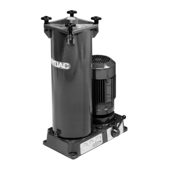
- Page 1 OF5 S/N OfflineFiltration Installation and Maintenance Instructions English • (translation of original instructions) Document No. : 3160336d • 9/13/2019 Follow these instructions for proper and safe use. Keep for future reference.
-
Page 2: Table Of Contents
Table of Contents HYDAC FILTER SYSTEMS GMBH Table of Contents 1 General ........................ 5 Imprint ...................... 5 Documentation Representative................ 5 Purpose of this manual .................. 6 Target group of the manual................ 6 Illustrations in the manual ................ 7 1.5.1 Illustration on the title page.............. 7 1.5.2... - Page 3 HYDAC FILTER SYSTEMS GMBH Table of Contents Hydraulic diagram .................. 28 3.5.1 OF5 N - Hydraulic diagram .............. 28 3.5.2 OF5 S - Hydraulic diagram .............. 29 Technical Data .................... 30 Decoding the name plate ................ 32 3.7.1 Model code .................. 34 Requirements of the workplace &...
- Page 4 Table of Contents HYDAC FILTER SYSTEMS GMBH Changing the filter element ................ 55 8 Rectifying malfunctions ................... 59 9 Decommissioning / Disposal ................... 61 10 Appendix ......................... 62 10.1 EC declaration of conformity ................ 62 10.2 Locating spare parts.................. 62 10.2.1 Order filter elements ................
-
Page 5: General
HYDAC FILTER SYSTEMS GMBH General | 1 1 General In this chapter, you will find helpful notes on handling these in- structions. 1.1 Imprint Manufacturer / publisher and responsible for the content: Address of the manufacturer Contact address HYDAC FILTER SYSTEMS... -
Page 6: Purpose Of This Manual
1 | General HYDAC FILTER SYSTEMS GMBH 1.3 Purpose of this manual Before you use this product for the first time or if you have been asked to carry out other work on the product, please read this manual. The use and the handling of the product described in the fol-... -
Page 7: Illustrations In The Manual
HYDAC FILTER SYSTEMS GMBH General | 1 1.5 Illustrations in the manual You will find illustrations in this manual. You can find details re- garding these in the following chapters. 1.5.1 Illustration on the title page You will find the following information on the title page of this... -
Page 8: Representation Of Requirements
1 | General HYDAC FILTER SYSTEMS GMBH The document no. with the index (4) is meant for identifying and reordering the manual. The index is incremented every time the manual is revised or changed. The manual contains a table of contents, a list of tables and figures, an index and a glossary. -
Page 9: Representation Of Intermediate Results/Results
HYDAC FILTER SYSTEMS GMBH General | 1 An example of a procedural instruction with a random se- quence: – Clean the display. – Rinse the product. 1.5.4 Representation of intermediate results/results In the case of some activities, it is necessary to carry out work steps with intermediate results and end results. -
Page 10: Representation Of Warning/General Safety Information
1 | General HYDAC FILTER SYSTEMS GMBH 1.5.5 Representation of warning/general safety information All the warning / general safety information in this manual are highlighted with pictograms and signal words. The pictogram and the signal word give you an indication of the severity of the danger. -
Page 11: Signal Words And Their Meaning In The General Safety Information
HYDAC FILTER SYSTEMS GMBH General | 1 1.5.6 Signal words and their meaning in the general safety information In these instructions you will find the following signal words: DANGER DANGER – The signal word indicates a hazardous situation with a high level of risk, which, if not avoided, will result lethal or serious injury. -
Page 12: Hazard Symbols / Pictograms
1 | General HYDAC FILTER SYSTEMS GMBH 1.6 Hazard symbols / pictograms The following are the safety symbols / pictograms in this man- ual. They indicate specific dangers to persons, property or to the environment. Observe these safety symbols / pictograms and act with particular caution in such cases. -
Page 13: Supplementary Symbols
HYDAC FILTER SYSTEMS GMBH General | 1 Exposed electrical components Danger due to operating pressure Signs used for the required specialist personnel These symbols show the required training/knowledge for in- stallation work and/or maintenance work. Specialist personnel - Electrician Such persons have specific specialist training and several years' work experience. -
Page 14: Exclusion Of Liability/Warranty
1 | General HYDAC FILTER SYSTEMS GMBH Required tools 1.8 Exclusion of liability/warranty For the warranty provided by us, please refer to the Terms of Delivery. They are made available to you at the conclusion of the contract at the latest. You will also find these under www.hydac.com ->... -
Page 15: Validity Of This Manual
HYDAC FILTER SYSTEMS GMBH General | 1 1.10 Validity of this manual The diagrams and visualizations in this manual are meant for general illustration purposes. Therefore, representations and functional options can deviate from the delivered product. We reserve the right to changes to the contents of this manual without prior notice. -
Page 16: Safety Information
2 | Safety information HYDAC FILTER SYSTEMS GMBH 2 Safety information DANGER Danger due to unintended use Bodily injury / Damage to property u Never operate the filter unit in potentially explosive atmos- pheres. u The filter unit is to be used only with the permissible oper- ating media. -
Page 17: Fire-Fighting / Extinguishing A Fire
HYDAC FILTER SYSTEMS GMBH Safety information | 2 The General Safety Information provides important information on handling the device. A prerequisite for safe work is the maintenance of all stated General Safety Instructions and pre- cautions. In addition, the local accident prevention specifica- tions and general safety regulations that apply for the area of operation of the device must be observed. -
Page 18: Stoppage In An Emergency (Emergency Stop)
2 | Safety information HYDAC FILTER SYSTEMS GMBH 2.2 Stoppage in an emergency (EMERGENCY STOP) Disconnect the product from all sources of energy in an emer- gency. 2.3 Observing regulatory information Observe the following regulatory information and directives: – Legal and local regulations for accident prevention –... -
Page 19: Overview Of The Filtration Unit
HYDAC FILTER SYSTEMS GMBH Overview of the filtration unit | 3 3 Overview of the filtration unit The OF5 S/N is a filter unit for offline filtration of hydraulic tanks. For the OF5 S version, it is possible to fill as well as empty a hydraulic tank with an integrated change over valve in addition to the offline filtration. -
Page 20: Proper/Designated Use
3 | Overview of the filtration unit HYDAC FILTER SYSTEMS GMBH 3.1 Proper/designated use Use the filter unit only for the application described in the fol- lowing. The filter unit is used in combination with the permitted filter el- ements (identification -KB) to clean / filter hydraulic and lubri- cating oils in the bypass flow or to fill the hydraulic systems, to transfer as well as drain the hydraulic tanks. -
Page 21: Improper Use Or Use Deviating From Intended Use
3.2 Improper use or use deviating from intended use Any use extending beyond this or deviating therefrom shall not be considered intended use. HYDAC FILTER SYSTEMS GMBH will assume no liability for any damage resulting from such use. This risk is borne solely by the owner. -
Page 22: Checking The Scope Of Delivery
3 | Overview of the filtration unit HYDAC FILTER SYSTEMS GMBH 3.3 Checking the scope of delivery The filter unit is delivered ready for connection without the filter element installed. Before commissioning the unit, check the contents of the package to make sure everything is present. -
Page 23: Dimensions
HYDAC FILTER SYSTEMS GMBH Overview of the filtration unit | 3 3.4 Dimensions Depending on the version, the filter housing/filter unit has dif- ferent dimensions. You can find details regarding these in the following chapters. MoWa OF5 S_N 3160336d en-us lq... -
Page 24: Of5N - Dimensions
3 | Overview of the filtration unit HYDAC FILTER SYSTEMS GMBH 3.4.1 OF5N - Dimensions The filter unit OF5N has following dimensions. Fig. 4: Dimensions OF5N 3433890 All dimensions in mm. 24 / 84 MoWa OF5 S_N 3160336d en-us lq... - Page 25 HYDAC FILTER SYSTEMS GMBH Overview of the filtration unit | 3 2 Inlet (A) 4 Outlet (T) 7 Motor-pump assembly 8 Filter housing 11 Filter housing bleeding BLEED 12 Filter housing drain DRAIN 13 Differential pressure indicator (optional) MoWa OF5 S_N 3160336d en-us lq...
-
Page 26: Of5S - Dimensions
3 | Overview of the filtration unit HYDAC FILTER SYSTEMS GMBH 3.4.2 OF5S - Dimensions The filter unit OF5S has following dimensions. Fig. 5: OF5S 3435194 Dimensions All dimensions in mm. 26 / 84 MoWa OF5 S_N 3160336d en-us lq... - Page 27 HYDAC FILTER SYSTEMS GMBH Overview of the filtration unit | 3 2 Connection (A), G1 according to INLET ISO 228 3 Connection (B), G1 according to ISO 228 4 Connection (T), G1 according to TANK / OUT ISO 228 5 Change-over valve 6 Locking pin...
-
Page 28: Hydraulic Diagram
3 | Overview of the filtration unit HYDAC FILTER SYSTEMS GMBH 3.5 Hydraulic diagram The hydraulic diagram of the filter unit varies depending on the version. 3.5.1 OF5 N - Hydraulic diagram The filter unit OF5 N has the following hydraulic diagram. -
Page 29: Of5 S - Hydraulic Diagram
HYDAC FILTER SYSTEMS GMBH Overview of the filtration unit | 3 3.5.2 OF5 S - Hydraulic diagram The filter unit OF5 S has the following hydraulic diagram. Fig. 7: Hydraulic circuit OF5 S 2 Connection (A), G1 according to INLET ISO 228 3 Connection (B), G1 according to OUTLET ISO 228... -
Page 30: Technical Data
3 | Overview of the filtration unit HYDAC FILTER SYSTEMS GMBH 3.6 Technical Data The filter unit has the following technical data: Permissible operating fluid Mineral oils and mineral oil- based raffinates. Permitted operating pres- ≤ 4.5 bar sure Hydraulic connections 1“ according to ISO 228... -
Page 31: Tab. 5 Technical Data
HYDAC FILTER SYSTEMS GMBH Overview of the filtration unit | 3 Storage duration unlimited Replace all the seals before commissioning after a storage duration of ≥ 2 years. Electrical power consump- OF5x10x3 ≈ 0.75 kW@50Hz tion OF5x10x4 ≈ 1.5 kW@50Hz OF5x10x6 Degree of protection... -
Page 32: Decoding The Name Plate
3 | Overview of the filtration unit HYDAC FILTER SYSTEMS GMBH 3.7 Decoding the name plate Identification details of the filter unit can be found on the name plates on the filter unit and the components. Always mention the part no. and the serial no. when contacting HYDAC. -
Page 33: Tab. 6 Decoding The Type Label
HYDAC FILTER SYSTEMS GMBH Overview of the filtration unit | 3 Item Description Current -> Current consumption Pressure max. -> Operating pressure, maximum Weight -> Empty weight Flow rate -> Flow rate Temp. Oil -> Permissible oil temperature range Temp. Amb. -
Page 34: Model Code
3 | Overview of the filtration unit HYDAC FILTER SYSTEMS GMBH 3.7.1 Model code The filter unit is defined by the following model code: OF5 S 10 P 6 N 1 B 05 E Basic Type Models = Filter unit with change over... -
Page 35: Requirements Of The Workplace & Working Environment
HYDAC FILTER SYSTEMS GMBH Overview of the filtration unit | 3 3.8 Requirements of the workplace & working environment Requirements of the workplace as well as the working environ- ment can be found in the chapter "Technical data" under: – Permitted ambient temperature range –... -
Page 36: Components / Operating Elements
3 | Overview of the filtration unit HYDAC FILTER SYSTEMS GMBH 3.9 Components / Operating elements The filter unit has the following components/operating ele- ments: Fig. 10: Components/operating elements (example: OF5S) 36 / 84 MoWa OF5 S_N 3160336d en-us lq... - Page 37 HYDAC FILTER SYSTEMS GMBH Overview of the filtration unit | 3 Item Tool Subplate Connection (A) Connection (B) IN / OUT Connection (T) TANK Change-over valve (only OF5S) Locking pin (only OF5S) Motor-pump assembly Filter housing Swing bolts Filter cover...
-
Page 38: Transporting/Storing The Filter Unit
4 | Transporting/storing the filter unit HYDAC FILTER SYSTEMS GMBH 4 Transporting/storing the filter unit Fully empty the filter unit before transporting it or putting it into storage. Remove the used filter element and dispose of it in an environmentally friendly manner. Clean the inside of the filter housing. -
Page 39: Setting Up / Assembly / Integration Of The Filter Unit
HYDAC FILTER SYSTEMS GMBH Setting up / assembly / integration of the filter unit | 5 5 Setting up / assembly / integration of the filter unit Observe the following notices for mounting the filter unit. – Place the filter unit horizontally on a stable, even and hori- zontal surface. -
Page 40: Avoiding Siphoning
5 | Setting up / assembly / integration of the filter unit HYDAC FILTER SYSTEMS GMBH 5.1 Avoiding siphoning If there is a height difference (ΔH) between the suction side and pressure side container/system, the lower line can develop a suction effect and trigger the siphoning effect between the communicating containers/systems. -
Page 41: Measure Or Display Dynamic Pressure / Differential Pressure
HYDAC FILTER SYSTEMS GMBH Setting up / assembly / integration of the filter unit | 5 5.2 Measure or display dynamic pressure / differential pressure If pressure is measured in a hydraulic system, the type of mea- surement such as dynamic pressure or differential pressure as well as the measurement point is critical, as shown in the following diagram. -
Page 42: Avoiding The Mixing Of Oils - Emptying The Filter Unit
5 | Setting up / assembly / integration of the filter unit HYDAC FILTER SYSTEMS GMBH 5.3 Avoiding the mixing of oils - Emptying the filter unit If you want to use the same oil for operation as in the previous operation, it is not serious if the oils are mixed. -
Page 43: Making The Electrical Connections
HYDAC FILTER SYSTEMS GMBH Setting up / assembly / integration of the filter unit | 5 5.4 Making the electrical connections Depending on the version, the filter unit has different drive mo- tors (different voltage / output / number of phases, etc.). Follow the instructions in the next section to electrically connect the fil- ter unit. -
Page 44: Fig. 14 Star Delta Connection
5 | Setting up / assembly / integration of the filter unit HYDAC FILTER SYSTEMS GMBH Fig. 14: Star delta connection Star connection Delta connection Check the direction of rotation on the electric motor in manual operation. An arrow on the pump shows the correct direction of rotation. -
Page 45: Connecting The Electric Clogging Indicator (Optional)
HYDAC FILTER SYSTEMS GMBH Setting up / assembly / integration of the filter unit | 5 5.6 Connecting the electric clogging indicator (optional) If the filter housing/filter unit has been fitted with an optional electric clogging indicator, connect it to your control center in accordance with the switching logic. - Page 46 5 | Setting up / assembly / integration of the filter unit HYDAC FILTER SYSTEMS GMBH This formula applies to straight pipe runs. Particularly with re- gard to the suction side connection, note that additional con- nectors and pipe bends increase the pressure differential.
-
Page 47: Inserting The Filter Element
HYDAC FILTER SYSTEMS GMBH Setting up / assembly / integration of the filter unit | 5 5.8 Inserting the filter element The filter unit has no filter element installed upon delivery from the factory. Before commissioning check whether a filter ele- ment is present in the filter housing. - Page 48 5 | Setting up / assembly / integration of the filter unit HYDAC FILTER SYSTEMS GMBH 1. Switch the filter unit on and monitor the suction perfor- mance. ð If the filter unit is not pumping any fluid after a maxi-...
-
Page 49: Operation
HYDAC FILTER SYSTEMS GMBH Operation | 6 6 Operation Different operating modes are available depending on the ver- sion (see the model code) of the filter unit. The filter unit is equipped with a clogging indicator (differential pressure gauge or dynamic pressure indicator) in the filter bowl cover to monitor the service life of the filter element. -
Page 50: Of5N - Operating Mode
6 | Operation HYDAC FILTER SYSTEMS GMBH 6.1 OF5N – Operating mode The filter unit OF5N cannot change over between the operat- ing modes. This filter unit can only be operated in the operation mode - Transfer with filtration. Fig. 16: OF5N - Transferring and filtering operating mode... -
Page 51: Of5S - Selecting Operating Modes
HYDAC FILTER SYSTEMS GMBH Operation | 6 6.2 OF5S - Selecting operating modes The filter unit OF5S has a change over valve for changing the operating modes over. See chapter Operating the change over valve [} 52] for changing the operating modes over. -
Page 52: Operating The Change Over Valve
6 | Operation HYDAC FILTER SYSTEMS GMBH 6.2.1 Operating the change over valve Select the operating modes via the change over valve. Unlock the change over valve by pulling the locking pin (6) in the cen- tre position before changing over. -
Page 53: Operating Mode - Transfer Without Filtration A -> B
HYDAC FILTER SYSTEMS GMBH Operation | 6 6.2.2 Operating mode - Transfer without filtration A -> B For the operating mode - Transfer without filtration -, move the change over valve in position I. The fluid will be pumped from the connection A to connection B. -
Page 54: Operating Mode - Transfer With Filtration T -> B
6 | Operation HYDAC FILTER SYSTEMS GMBH 6.2.4 Operating mode - Transfer with filtration T -> B For the operating mode - Transfer with filtration -, move the change over valve to position III. The fluid will be pumped from connection T to connection B. For details see figure. -
Page 55: Performing Maintenance
HYDAC FILTER SYSTEMS GMBH Performing maintenance | 7 7 Performing maintenance 7.1 Maintenance table Additional information Operation Changing the fil- ter element Changing the fil- ter element 1 - Operating personnel 7.2 Changing the filter element In this chapter, you will find the procedure for changing the fil- ter element. - Page 56 7 | Performing maintenance HYDAC FILTER SYSTEMS GMBH BLEED 1. Depressurize the filter housing. Remove the bleed screw (BLEED) in the filter cover. 2. Place a suitable container under the connection Empty the filter housing. Drain the residual oil volume from the filter housing via the drain ball valve (DRAIN) in a suitable container.
- Page 57 HYDAC FILTER SYSTEMS GMBH Performing maintenance | 7 7. For easier installation of the filter element, moisten the O-ring on the filter element with the operating medium / oil. 8. Press the new filter element down into the filter seat by turning it slightly.
- Page 58 7 | Performing maintenance HYDAC FILTER SYSTEMS GMBH BLEED 13. Switch the filter unit on and bleed the filter housing via the connection (BLEED). Unscrew the bleed screws with ≈ four turns and wait till the oil emits on the bleed screws (BLEED). Subse- quently close the bleed screw (BLEED).
-
Page 59: Rectifying Malfunctions
HYDAC FILTER SYSTEMS GMBH Rectifying malfunctions | 8 8 Rectifying malfunctions The following malfunctions may occur during handling or oper- ation of the filter housing: Malfunction Cause(s) Rectification No function. No electric ten- Check the feed- sion. line, fuse and The motor pump the main switch. -
Page 60: Tab. 7 Error / Cause / Rectification
8 | Rectifying malfunctions HYDAC FILTER SYSTEMS GMBH Malfunction Cause(s) Rectification The dynamic The fluid is Replace the filter pressure up- heavily contami- element. stream of the fil- nated. ter is high. The contamina- (Clogging indica- tion retention ca- tor is activated) -
Page 61: Decommissioning / Disposal
HYDAC FILTER SYSTEMS GMBH Decommissioning / Disposal | 9 9 Decommissioning / Disposal – Empty the product completely, including all of its compo- nents, before decommissioning. Disconnect or remove the electric, pneumatic or hydraulic connections. – Dispose of the packaging material in an environmentally friendly manner. -
Page 62: Appendix
10 | Appendix HYDAC FILTER SYSTEMS GMBH 10 Appendix In this annex, you will find supplementary information on the product. 10.1 EC declaration of conformity The ED declaration of conformity can be found in the Technical Documentation that is part of the scope of delivery for the product. -
Page 63: Tab. 8 Spare Parts List Of5
HYDAC FILTER SYSTEMS GMBH Appendix | 10 Description Part no. Differential pressure indicator FKM 316556 Tab. 8: Spare parts list OF5… *) available on request MoWa OF5 S_N 3160336d en-us lq 63 / 84... -
Page 64: Order Filter Elements
10 | Appendix HYDAC FILTER SYSTEMS GMBH 10.2.1 Order filter elements Select the filter element depending on size of your filter unit. In the following you can find the filter elements as per size, filter unit and sealing material. 10.2.1.1 Filter element - Size 330... -
Page 65: Tab. 10 Filter Elements - Size 1300
HYDAC FILTER SYSTEMS GMBH Appendix | 10 Description Part no. Filter element 10 µm 1300 R 010 ON/-V- FPM 1263762 Filter element 20 µm 1300 R 020 ON/-KB NBR 1263062 Filter element 20 µm 1300 R 020 ON/-V- FPM 1263763 Filter element 40 µm 1300 R 040 AM/-KB NBR 1267699 Tab. 10: Filter elements - size 1300... -
Page 66: Filter Elements - Size 2600
10 | Appendix HYDAC FILTER SYSTEMS GMBH 10.2.1.3 Filter elements - size 2600 In this chapter you can find the filter elements of the size 2600: Description Part no. Filter element 3 µm 2600 R 003 ON/-KB NBR 1263071 Filter element 3 µm 2600 R 003 ON/-V- FPM 1263784 Filter element 3 µm... -
Page 67: Clogging Indicators - Technical Data
HYDAC FILTER SYSTEMS GMBH Appendix | 10 10.3 Clogging indicators - technical data Listed below are the technical data pertaining to the optional, optical or electrical clogging indicators suitable for the installa- tion in the filter housing / filter unit. -
Page 68: Tab. 12: Differential Pressure Indicator -Visual Vm X B.x
10 | Appendix HYDAC FILTER SYSTEMS GMBH Permissible operating over- ≤ 210 bar pressure Permitted temperature range -30 … +100°C Connector threads G ½ Installation space required According to HN 28-22 Maximum tightening torque 33 Nm Tab. 12: Differential pressure indicator -visual VM x B.x 68 / 84 MoWa OF5 S_N 3160336d en-us lq... -
Page 69: Differential Pressure Indicator, Visual - Vm X Bm.x
HYDAC FILTER SYSTEMS GMBH Appendix | 10 10.3.2 Differential pressure indicator, visual – VM x BM.x The optical differential pressure gauge reacts to the increasing pressure difference at the increasing contamination level of the filter element. Fig. 23: Differential pressure gauge, visual VM x BM.x... -
Page 70: Tab. 13: Differential Pressure Indicator, Visual Vm X Bm.x
10 | Appendix HYDAC FILTER SYSTEMS GMBH Permissible operating over- ≤ 210 bar pressure Permitted temperature range -30 … +100°C Connector threads G ½ Installation space required According to HN 28-22 Tab. 13: Differential pressure indicator, visual VM x BM.x 70 / 84 MoWa OF5 S_N 3160336d en-us lq... -
Page 71: Differential Pressure Gauge, Electric (Vm X C.x)
HYDAC FILTER SYSTEMS GMBH Appendix | 10 10.3.3 Differential pressure gauge, electric (VM x C.x) The electric clogging indicator reacts to the increasing pres- sure difference at the increasing contamination level of the fil- ter element. Fig. 24: Differential pressure indicator, electrical VM x C.x... -
Page 72: Tab. 14: Differential Pressure Indicator, Electrical Vm X C.x
10 | Appendix HYDAC FILTER SYSTEMS GMBH Response pressure and indi- VM 2 C.x = 2 bar -10% cation range respectively VM 3 C.x = 3 bar -10% VM 5 C.x = 5 bar -10% Permissible operating over- ≤ 210 bar pressure Permitted temperature range -30 … +100°C Connector threads G ½ Installation space required According to HN 28-22 Maximum tightening torque 33 Nm... -
Page 73: Differential Pressure Gauge, Electric (Vm X D.x /-L-Xx)
HYDAC FILTER SYSTEMS GMBH Appendix | 10 10.3.4 Differential pressure gauge, electric (VM x D.x /-L- The electric clogging indicator reacts to the increasing pres- sure difference at the increasing contamination level of the fil- ter element. Fig. 25: Differential pressure indicator, electrical VM x D.x /-Lxx... -
Page 74: Tab. 15 Differential Pressure Indicator, Electrical Vm X D.x / -Lxx
10 | Appendix HYDAC FILTER SYSTEMS GMBH Response pressure and indi- VM 2 D.x = 2 bar -10% cation range respectively VM 3 D.x = 3 bar -10% VM 5 D.x = 5 bar -10% Permissible operating over- ≤ 210 bar pressure Permitted temperature range -30 … +100°C Connector threads G ½ Installation space required According to HN 28-22 Maximum tightening torque 33 Nm... -
Page 75: Finding A Customer Service Team
HYDAC FILTER SYSTEMS GMBH Appendix | 10 10.4 Finding a Customer Service team The contact data such as the telephone numbers, e-mail and mailing addresses for the hotline, product support, customer service, branch offices, service partners for servicing, repair and spare parts can be found, always updated, at our home- page www.hydac.com. - Page 76 Table of Illustrations HYDAC FILTER SYSTEMS GMBH Table of Illustrations Fig. 1 Overview / labeling of the title page ............Fig. 2 Fire protection class B ................Fig. 3 Minimum distance for fire fighting............. Fig. 4 Dimensions OF5N 3433890 ..............
- Page 77 HYDAC FILTER SYSTEMS GMBH Table of Illustrations Fig. 25 Differential pressure indicator, electrical VM x D.x /-Lxx ......MoWa OF5 S_N 3160336d en-us lq 77 / 84...
- Page 78 Index of Tables HYDAC FILTER SYSTEMS GMBH Index of Tables Tab. 1 Impressum....................Tab. 2 Documentation Representative ..............Tab. 3 Target group ..................... Tab. 4 Checking the scope of delivery ..............Tab. 5 Technical Data ..................Tab. 6 Decoding the type label ................
-
Page 79: Glossary
HYDAC FILTER SYSTEMS GMBH Glossary Glossary General Terms and Conditions The General Terms and Conditions are available at our home page www.hydac.com -> General Terms and Conditions. HN 28-22 HYDAC standard 28-22 with dimen- sions for the installation space for clogging indicators. -
Page 80: Index
Index HYDAC FILTER SYSTEMS GMBH Index Branches 75 Hotline 75 calculating pressure loss 45 Imprint 5 Clogging indicator Differential pressure indicator 68, 70, 72, 74 manufacturer 5 Commissioning 47 Operating mode decommissioning 61 Transfer with filtration A -> T 53 Delta connection 44... - Page 81 HYDAC FILTER SYSTEMS GMBH Index Terms and Conditions 14 Terms of Delivery 14 warranty 14 MoWa OF5 S_N 3160336d en-us lq 81 / 84...
Need help?
Do you have a question about the OF5 S Series and is the answer not in the manual?
Questions and answers