Table of Contents
Advertisement
Quick Links
Advertisement
Chapters
Table of Contents

Related Manuals for HYDAC FILTER SYSTEMS OLFCM 5/15


Summary of Contents for HYDAC FILTER SYSTEMS OLFCM 5/15
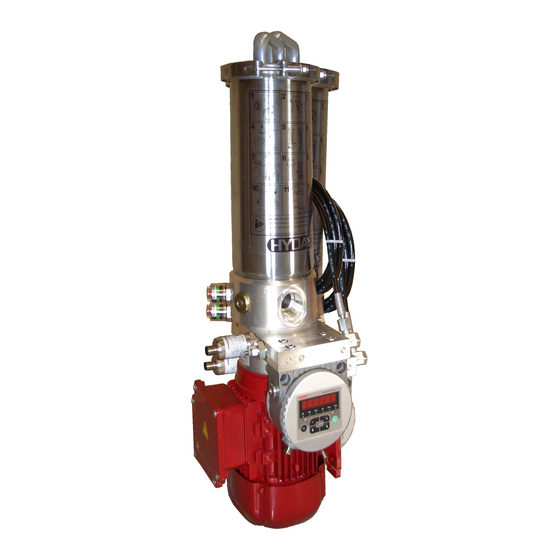
- Page 1 OLFCM 5/15 OLFCM 10/15 Offline Filter Compact Installation and Maintenance Instructions English • (translation of original instructions) Document No. : 3573893a • 10/2/2019 Follow these instructions for proper and safe use. Keep for future reference.
-
Page 2: Table Of Contents
Table of Contents HYDAC FILTER SYSTEMS GMBH Table of Contents 1 General ........................ 5 Imprint ...................... 5 Documentation Representative................ 5 Purpose of this manual .................. 6 Target group of the manual................ 6 Illustrations in the manual ................ 7 1.5.1 Illustration on the title page.............. 7 1.5.2... - Page 3 HYDAC FILTER SYSTEMS GMBH Table of Contents 5 Mounting/installing .................... 36 Fastening/mounting the filter unit .............. 36 Avoiding siphoning .................. 39 Observing/calculating pressure loss .............. 40 Measure or display dynamic pressure / differential pressure...... 42 Connecting the (IN) suction port .............. 43 Connecting the pressure port (OUT)..............
- Page 4 Table of Contents HYDAC FILTER SYSTEMS GMBH 9.2.3 Differential pressure gauge, electric (VM x C.x) ........ 69 9.2.4 Differential pressure gauge, electric (VM x D.x /-L-xx) ...... 71 Finding a Customer Service team.............. 73 Glossary ........................ 76 Index ........................ 79...
-
Page 5: General
HYDAC FILTER SYSTEMS GMBH General | 1 1 General In this chapter, you will find helpful notes on handling these in- structions. 1.1 Imprint Manufacturer / publisher and responsible for the content: Address of the manufacturer Contact address HYDAC FILTER SYSTEMS... -
Page 6: Purpose Of This Manual
1 | General HYDAC FILTER SYSTEMS GMBH 1.3 Purpose of this manual Before you use this product for the first time or if you have been asked to carry out other work on the product, please read this manual. The use and the handling of the product described in the fol-... -
Page 7: Illustrations In The Manual
HYDAC FILTER SYSTEMS GMBH General | 1 1.5 Illustrations in the manual You will find illustrations in this manual. You can find details re- garding these in the following chapters. 1.5.1 Illustration on the title page You will find the following information on the title page of this... -
Page 8: Representation Of Requirements
1 | General HYDAC FILTER SYSTEMS GMBH The document no. with the index (4) is meant for identifying and reordering the manual. The index is incremented every time the manual is revised or changed. The manual contains a table of contents, a list of tables and figures, an index and a glossary. -
Page 9: Representation Of Intermediate Results/Results
HYDAC FILTER SYSTEMS GMBH General | 1 An example of a procedural instruction with a random se- quence: – Clean the display. – Rinse the product. 1.5.4 Representation of intermediate results/results In the case of some activities, it is necessary to carry out work steps with intermediate results and end results. -
Page 10: Representation Of Warning/General Safety Information
1 | General HYDAC FILTER SYSTEMS GMBH 1.5.5 Representation of warning/general safety information All the warning / general safety information in this manual are highlighted with pictograms and signal words. The pictogram and the signal word give you an indication of the severity of the danger. -
Page 11: Signal Words And Their Meaning In The General Safety Information
HYDAC FILTER SYSTEMS GMBH General | 1 1.5.6 Signal words and their meaning in the general safety information In these instructions you will find the following signal words: DANGER DANGER – The signal word indicates a hazardous situation with a high level of risk, which, if not avoided, will result lethal or serious injury. -
Page 12: Hazard Symbols / Pictograms
1 | General HYDAC FILTER SYSTEMS GMBH 1.6 Hazard symbols / pictograms The following are the safety symbols / pictograms in this man- ual. They indicate specific dangers to persons, property or to the environment. Observe these safety symbols / pictograms and act with particular caution in such cases. -
Page 13: Supplementary Symbols
HYDAC FILTER SYSTEMS GMBH General | 1 Exposed electrical components Danger due to operating pressure Signs used for the required specialist personnel These symbols show the required training/knowledge for in- stallation work and/or maintenance work. Specialist personnel - Electrician Such persons have specific specialist training and several years' work experience. -
Page 14: Exclusion Of Liability/Warranty
1 | General HYDAC FILTER SYSTEMS GMBH Required tools 1.8 Exclusion of liability/warranty For the warranty provided by us, please refer to the Terms of Delivery. They are made available to you at the conclusion of the contract at the latest. You will also find these under www.hydac.com ->... -
Page 15: Validity Of This Manual
HYDAC FILTER SYSTEMS GMBH General | 1 1.10 Validity of this manual The diagrams and visualizations in this manual are meant for general illustration purposes. Therefore, representations and functional options can deviate from the delivered product. We reserve the right to changes to the contents of this manual without prior notice. -
Page 16: Safety Information
2 | Safety information HYDAC FILTER SYSTEMS GMBH 2 Safety information The General Safety Information provides important information on handling the device. A prerequisite for safe work is the maintenance of all stated General Safety Instructions and pre- cautions. In addition, the local accident prevention specifica- tions and general safety regulations that apply for the area of operation of the device must be observed. - Page 17 HYDAC FILTER SYSTEMS GMBH Safety information | 2 NOTICE Siphoning effect Reservoir overflowing/leaking = oil spill u Remove the ends of the hoses from the reservoir after op- eration or shut the shut-off device in the suction line. NOTICE Pressure port/outlet OUT closed...
-
Page 18: Filter Unit/Filter Housing Over-View
3 | Filter unit/filter housing over-view HYDAC FILTER SYSTEMS GMBH 3 Filter unit/filter housing over-view The filter units of the OLF-5 and OLF-10 series are used for the fine filtration of hydraulic oils in bypass flow. The series has many versions e.g. with or without the motor-pump unit, ele-... -
Page 19: Proper/Designated Use
HYDAC FILTER SYSTEMS GMBH Filter unit/filter housing over-view | 3 3.1 Proper/designated use Use the filter/filter unit only for the application described in the following: The filter/filter unit is designed for the fine filtration of lubricat- ing and hydraulic oils in bypass flow. -
Page 20: Improper Use Or Use Deviating From Intended Use
3 | Filter unit/filter housing over-view HYDAC FILTER SYSTEMS GMBH 3.2 Improper use or use deviating from intended use DANGER Danger due to unintended use Bodily injury and damage to property u Never operate the filter unit in potentially explosive atmos- pheres. -
Page 21: Checking The Scope Of Delivery
HYDAC FILTER SYSTEMS GMBH Filter unit/filter housing over-view | 3 3.3 Checking the scope of delivery The filter unit/filter is delivered packed and ready for use. Please check the filter unit for possible damage before com- missioning. Immediately report any damage in transit to the forwarding agent or the HYDAC department in charge. -
Page 22: Decoding The Type Label
3 | Filter unit/filter housing over-view HYDAC FILTER SYSTEMS GMBH 3.4 Decoding the type label For identification details of the filter housing, see the name plate. Fig. 3: Decoding model code Item Description (1) - Filter unit nameplate (2) - Filter unit model code... -
Page 23: Model Code
HYDAC FILTER SYSTEMS GMBH Filter unit/filter housing over-view | 3 Voltage/Grid - Voltage/power supply Frequency - Frequency Current - Current consumption P max - Operating pressure, maximum Flow rate - Flow rate Weight - Empty weight 3.4.1 Model code The filter unit/filter housing is defined by the following model... -
Page 24: Fig. 4 Model Code
3 | Filter unit/filter housing over-view HYDAC FILTER SYSTEMS GMBH OLFCM - 5/15 - T - xxx-x - NxXMxxx - xx Basic Type OLFCM = OffLine Filter ConditionMonitoring Size / flow rate 5/15 = 15 l/min 10/15 = 15 l/min... -
Page 25: Tab. 5 Over-View - Electric Motors, Power/Supply Voltage
HYDAC FILTER SYSTEMS GMBH Filter unit/filter housing over-view | 3 OLF-5 OLF-5/4 OLF-5/15 5 l/min 4 l/min 15 l/min 120-N 120 W, 3x400 V, 50 Hz 120-M 120 W, 1x230 V, 50 Hz 120-K 120 W, 1x120 V, 60 Hz 370-N 370 W, 3x400 V, 50 Hz 370 W, 3x440 V … 480 V, 60 Hz 370-M 370 W, 1x230 V, 50 Hz 370-K 370 W, 1x120 V, 60 Hz... -
Page 26: Tab. 7 Over-View - Filter Elements N10Xmxxx
3 | Filter unit/filter housing over-view HYDAC FILTER SYSTEMS GMBH OLF-10 OLF-10/4 OLF-10/15 5 l/min 4 l/min 15 l/min N10DM001 Dimicron , Filtration rating, 1 µm (absolute) N10DM002 Dimicron, Filtration rating, 2 µm (absolute) N10DM005 Dimicron, Filtration rating, 5 µm (absolute) N10DM010 Dimicron, Filtration rating, 10 µm (absolute) N10DM020 Dimicron, Filtration rating, 20 µm (absolute) -
Page 27: Tab. 8 Over-View - Clogging Indicators
HYDAC FILTER SYSTEMS GMBH Filter unit/filter housing over-view | 3 OLF-5 OLF-5/4 OLF-5/15 5 l/min 4 l/min 15 l/min Without clogging indicator Tab. 8: Over-view - Clogging indicators (X) selection is possible, (-) selection is not possible MoWa OLFCM 3573893a en-us lq 27 / 80... -
Page 28: Technical Data
3 | Filter unit/filter housing over-view HYDAC FILTER SYSTEMS GMBH 3.5 Technical Data The filter unit has the following technical data: Bypass opening pressure ≈ 3.5 bar for the filter element Operating pressure ≈ 4.5 bar Permissible fluid contamina- < 12 NAS according to ISO4406 tion... -
Page 29: Tab. 9 Technical Data
HYDAC FILTER SYSTEMS GMBH Filter unit/filter housing over-view | 3 Connection OUTLET G1“ according to ISO 228 Connection DRAIN G1/2 according to ISO 228 AIR BLEEDconnection G1/4 according to ISO 228 Tab. 9: Technical Data MoWa OLFCM 3573893a en-us lq 29 / 80... -
Page 30: Dimensions / Hydraulic Diagram
3 | Filter unit/filter housing over-view HYDAC FILTER SYSTEMS GMBH 3.6 Dimensions / hydraulic diagram In this chapter, you will find the drawings with the dimensions and the hydraulic diagram of the different versions of the filter units/filter housings. 30 / 80... -
Page 31: Drawing Olfcm-5/15-T
HYDAC FILTER SYSTEMS GMBH Filter unit/filter housing over-view | 3 3.6.1 Drawing OLFCM-5/15-T-... / OLFCM-10/15-T-... Fig. 5: Dimensions of the 3486357 - OLFCM-5/15 / OLFCM-10/15 All dimensions are in mm. MoWa OLFCM 3573893a en-us lq 31 / 80... - Page 32 3 | Filter unit/filter housing over-view HYDAC FILTER SYSTEMS GMBH Item Tool Fluid inlet Fluid outlet DRAIN Draining/draining fluid AIR BLEED Bleeding/venting Clogging indicator Required space for removing the filter element Room required for cooling the electric motor 32 / 80...
-
Page 33: Components
HYDAC FILTER SYSTEMS GMBH Filter unit/filter housing over-view | 3 3.6.1.1 Components The filter unit has the following components: Fig. 6: Components of the OLFCM-5-T... / OLFCM-10-T... Item Tool Fluid inlet MoWa OLFCM 3573893a en-us lq 33 / 80... - Page 34 3 | Filter unit/filter housing over-view HYDAC FILTER SYSTEMS GMBH Item Tool Fluid outlet AIR BLE Air bleed DRAIN Draining/draining fluid Clogging indicator Electric motor Ventilator hood Terminal box Mounting base/electric motor base Filter bowl Housing clamp Filter housing cover 34 / 80...
-
Page 35: Transportation/Storage
HYDAC FILTER SYSTEMS GMBH Transportation/storage | 4 4 Transportation/storage Fully empty the filter unit/filter housing before transporting it or putting it into storage. Remove the used filter element/filter car- tridge and clean the inside of the filter housing. NOTICE Do not grip the filter unit/filter housing at the clogging indicator The clogging indicator will be damaged/destroyed. -
Page 36: Mounting/Installing
5 | Mounting/installing HYDAC FILTER SYSTEMS GMBH 5 Mounting/installing The following provides information on how to install and con- nect the filter unit/filter housing, hydraulically and electrically. 5.1 Fastening/mounting the filter unit The filter unit must be mounted vertically. Fix the filtration unit by means of four suitable screws, with the mounting base or the base on the electric motor, depending on the version. -
Page 37: Fig. 7 Assembling The Olf5Cm
HYDAC FILTER SYSTEMS GMBH Mounting/installing | 5 Fig. 7: Assembling the OLF5CM The dimensions, connections and circuit diagrams for the re- spective version can be found in the "Annex" chapter. MoWa OLFCM 3573893a en-us lq 37 / 80... - Page 38 5 | Mounting/installing HYDAC FILTER SYSTEMS GMBH If the oil level in the hydraulic system is higher than the filter housing, install additional shut-off devices at the inlet (IN)/outlet (OUT). These shut-off devices guarantee that the filter element change will be fast and clean.
-
Page 39: Avoiding Siphoning
HYDAC FILTER SYSTEMS GMBH Mounting/installing | 5 5.2 Avoiding siphoning If there is a height difference (ΔH) between the suction side and pressure side container/system, the lower line can develop a suction effect and trigger the siphoning effect between the communicating containers/systems. -
Page 40: Observing/Calculating Pressure Loss
5 | Mounting/installing HYDAC FILTER SYSTEMS GMBH 5.3 Observing/calculating pressure loss The pressure loss in a hydraulic line depends upon: – Flow – Kinematic viscosity – Pipe dimensions – Fluid density The pressure loss can be estimated as follows for mineral oil- based hydraulic oils: Fig. 9: Pressure loss formula... - Page 41 HYDAC FILTER SYSTEMS GMBH Mounting/installing | 5 – Make sure that the connection hoses/piping (suction side/ pressure side) do not cause any tension or vibrations to be carried over to the filter unit. Use hoses or expansion joints if necessary.
-
Page 42: Measure Or Display Dynamic Pressure / Differential Pressure
5 | Mounting/installing HYDAC FILTER SYSTEMS GMBH 5.4 Measure or display dynamic pressure / differential pressure If pressure is measured in a hydraulic system, the type of mea- surement such as dynamic pressure or differential pressure as well as the measurement point is critical, as shown in the following diagram. -
Page 43: Connecting The (In) Suction Port
HYDAC FILTER SYSTEMS GMBH Mounting/installing | 5 5.5 Connecting the (IN) suction port Use a connector that is suitable for the port. The size of the connection and the type of the threads can be found in the "Technical data" chapter... -
Page 44: Connecting The Pressure Port (Out)
5 | Mounting/installing HYDAC FILTER SYSTEMS GMBH 5.6 Connecting the pressure port (OUT) Use a connector that is suitable for the port. The size of the connection and the type of the threads can be found in the "Technical data" chapter... -
Page 45: Fig. 11 Star Delta Connection
HYDAC FILTER SYSTEMS GMBH Mounting/installing | 5 Fig. 11: Star delta connection Star connection Delta connection Check the direction of rotation on the electric motor in manual operation. An arrow on the pump shows the correct direction of rotation. If it is necessary to modify the direction of rotation, then exchange the two phases in the terminal box of the elec- tric motor. -
Page 46: Connecting The Electric Clogging Indicator (Optional)
5 | Mounting/installing HYDAC FILTER SYSTEMS GMBH 5.8 Connecting the electric clogging indicator (optional) If the filter housing/filter unit has been fitted with an optional electric clogging indicator, connect it to your control center in accordance with the switching logic. - Page 47 HYDAC FILTER SYSTEMS GMBH Mounting/installing | 5 ð If the pump pumps the operating medium, the installa- tion has been completed successfully. If the pump does not pump any medium after ≈ 2 min- utes, switch the filter unit off and fill the pump by hand via the suction line.
-
Page 48: Checking The Installation
5 | Mounting/installing HYDAC FILTER SYSTEMS GMBH 5.12 Checking the installation Check all the electric/hydraulic connections, screwed connec- tions and components for firm seating. After commissioning, check all the functions and for leaks. 48 / 80 MoWa OLFCM 3573893a en-us lq... -
Page 49: Operation
HYDAC FILTER SYSTEMS GMBH Operation | 6 6 Operation To monitor the service life of the filter element/filter cartridge during operation, the filter unit/filter housing is fitted with a clogging indicator (back pressure/differential pressure, optical or electric). Visually check the optical clogging indicator daily. See chapter Observing the optical clogging indicator (optional) [} 49]... -
Page 50: Rectifying Malfunctions
7 | Rectifying malfunctions HYDAC FILTER SYSTEMS GMBH 7 Rectifying malfunctions The following errors may occur during handling or operation of the filter unit/filter housing: Malfunction Cause(s) Rectification No flow The unit pumps Make sure that in the incorrect the pump pumps flow direction. -
Page 51: Tab. 10 Error/Cause/Rectification
HYDAC FILTER SYSTEMS GMBH Rectifying malfunctions | 7 Malfunction Cause(s) Rectification the circulation of the fluid within the pump (pres- sure relief valve opened) and normal pump op- eration has then started. Leakage at the The drain plug at Tighten the nuts... -
Page 52: Performing Maintenance
8 | Performing maintenance HYDAC FILTER SYSTEMS GMBH 8 Performing maintenance In this chapter, you will find the description of the required maintenance activities and the qualifications of the staff needed to carry out these tasks. WARNING The hydraulic system is under pressure during operation... -
Page 53: Maintenance Table
HYDAC FILTER SYSTEMS GMBH Performing maintenance | 8 8.1 Maintenance table 8.2 Resetting the VM x BM.x visual clogging indicator The VM x BM.x visual clogging indicator has a manual reset. Reset the clogging indicator by hand after every filter element replacement as shown below. -
Page 54: Changing The Filter Element - Toploader
8 | Performing maintenance HYDAC FILTER SYSTEMS GMBH 8.3 Changing the filter element - Toploader In this chapter, you will find the procedure for changing the fil- ter element. 1x Allen wrench = 5 mm 1x Allen wrench = 6 mm ü The following steps relate to a Toploader filter unit/filter housing. - Page 55 HYDAC FILTER SYSTEMS GMBH Performing maintenance | 8 2. Keep a suitable container ready to catch the escaping operating medium. The contents are ≈ 3 liters. Empty the filter housing by means of the drain plug Drain ( = 6 mm). NOTICE! Without draining equipment, the escaping operating medium can flow down over the electric motor.
- Page 56 8 | Performing maintenance HYDAC FILTER SYSTEMS GMBH 5. By rotating it clockwise by 90°, you loosen the dirt catch tray. 6. Remove the filter element from the filter bowl cover by rotating it clockwise by 90° and dispose of it in an envi- ronmentally friendly manner.
- Page 57 HYDAC FILTER SYSTEMS GMBH Performing maintenance | 8 10. Secure the dirt catch tray at the bottom of the filter ele- ment by turning it counterclockwise by 90°. 11. Place the filter element with the filter bowl cover and the dirt catch tray in the filter housing.
- Page 58 8 | Performing maintenance HYDAC FILTER SYSTEMS GMBH 16. Tighten the drain plug Drain ( = 6 mm). 17. Switch the filter unit/hydraulic system on and vent the fil- ter housing through the air bleed screw Air Bleed ( = 6 mm) in the filter bowl cover.
-
Page 59: Changing The Protective Screen
HYDAC FILTER SYSTEMS GMBH Performing maintenance | 8 8.4 Changing the protective screen In this chapter, you will find the steps for changing the protec- tive screen. 1x wrench = xx mm 1x wrench = xx mm A protective strainer is installed to protect the Contamination- Sensor from blocking up. -
Page 60: Fig. 14 Protective Screen/Pre-Filter Set
8 | Performing maintenance HYDAC FILTER SYSTEMS GMBH Fig. 14: Protective screen/pre-filter set A Screw connection B Screw connection 1 Protective screen, 100 µm 2 O-ring 60 / 80 MoWa OLFCM 3573893a en-us lq... -
Page 61: Appendix
HYDAC FILTER SYSTEMS GMBH Appendix | 9 9 Appendix 9.1 Finding spare parts / accessories Use only original spare parts and accessories. When ordering spare parts and accessories make sure to always indicate the exact model code and the serial number. - Page 62 9 | Appendix HYDAC FILTER SYSTEMS GMBH Item Qty. Tool Part no. 4.00 Filter element 10 µm N10DM010 3539238 DIMICRON 4.00 Filter element 20 µm N5DM020 3023508 DIMICRON 4.00 Filter element 20 µm N10DM020 3539242 DIMICRON 4.00 Filter element 2 µm N5AM002 349677 AQUAMICRON 4.00...
-
Page 63: Spare Parts - Toploader
HYDAC FILTER SYSTEMS GMBH Appendix | 9 9.1.1 Spare parts - Toploader The following spare parts are available for the Toploader ver- sion: Tool Part no. Drain screw with seal ring 617095 G1/4 Drain screw with seal ring 630700 G1/4 Housing clamp for... -
Page 64: Diagram Of Spare Part - Olfcm-X/Xx-T
9 | Appendix HYDAC FILTER SYSTEMS GMBH 9.1.2 Diagram of spare part - OLFCM-x/xx-T-... Toploader The following diagram shows the spare part for the OLFCM-x/xx-T-…: Fig. 15: OLFCM-x/xx-T - 32522084 spare parts 64 / 80 MoWa OLFCM 3573893a en-us lq... -
Page 65: Accessories - Tank Connection Kit Olf-5-Tak
HYDAC FILTER SYSTEMS GMBH Appendix | 9 9.1.3 Accessories - Tank Connection Kit OLF-5-TAK The Tank Connection Kit TAK is designed for the easy and quick retrofitting on an OLF filter unit on existing hydraulic sys- tems. The TAK can be used on all hydraulic systems with a breather filter according to the connection diagram DIN 24557/... -
Page 66: Clogging Indicators - Technical Data
9 | Appendix HYDAC FILTER SYSTEMS GMBH 9.2 Clogging indicators - technical data Listed below are the technical data pertaining to the optional, optical or electrical clogging indicators suitable for the installa- tion in the filter housing / filter unit. -
Page 67: Tab. 13: Differential Pressure Indicator -Visual Vm X B.x
HYDAC FILTER SYSTEMS GMBH Appendix | 9 Permissible operating over- ≤ 210 bar pressure Permitted temperature range -30 … +100°C Connector threads G ½ Installation space required According to HN 28-22 Maximum tightening torque 33 Nm Tab. 13: Differential pressure indicator -visual VM x B.x MoWa OLFCM 3573893a en-us lq... -
Page 68: Differential Pressure Indicator, Visual - Vm X Bm.x
9 | Appendix HYDAC FILTER SYSTEMS GMBH 9.2.2 Differential pressure indicator, visual – VM x BM.x The optical differential pressure gauge reacts to the increasing pressure difference at the increasing contamination level of the filter element. 68 / 80 MoWa OLFCM 3573893a en-us lq... -
Page 69: Differential Pressure Gauge, Electric (Vm X C.x)
HYDAC FILTER SYSTEMS GMBH Appendix | 9 9.2.3 Differential pressure gauge, electric (VM x C.x) The electric clogging indicator reacts to the increasing pres- sure difference at the increasing contamination level of the fil- ter element. Fig. 18: Differential pressure indicator, electrical VM x C.x... -
Page 70: Tab. 14: Differential Pressure Indicator, Electrical Vm X C.x
9 | Appendix HYDAC FILTER SYSTEMS GMBH Response pressure and indi- VM 2 C.x = 2 bar -10% cation range respectively VM 3 C.x = 3 bar -10% VM 5 C.x = 5 bar -10% Permissible operating over- ≤ 210 bar pressure Permitted temperature range -30 … +100°C Connector threads G ½ Installation space required According to HN 28-22 Maximum tightening torque 33 Nm... -
Page 71: Differential Pressure Gauge, Electric (Vm X D.x /-L-Xx)
HYDAC FILTER SYSTEMS GMBH Appendix | 9 9.2.4 Differential pressure gauge, electric (VM x D.x /-L- The electric clogging indicator reacts to the increasing pres- sure difference at the increasing contamination level of the fil- ter element. Fig. 19: Differential pressure indicator, electrical VM x D.x /-Lxx... -
Page 72: Tab. 15 Differential Pressure Indicator, Electrical Vm X D.x / -Lxx
9 | Appendix HYDAC FILTER SYSTEMS GMBH Response pressure and indi- VM 2 D.x = 2 bar -10% cation range respectively VM 3 D.x = 3 bar -10% VM 5 D.x = 5 bar -10% Permissible operating over- ≤ 210 bar pressure Permitted temperature range -30 … +100°C Connector threads G ½ Installation space required According to HN 28-22 Maximum tightening torque 33 Nm... -
Page 73: Finding A Customer Service Team
HYDAC FILTER SYSTEMS GMBH Appendix | 9 9.3 Finding a Customer Service team The contact data such as the telephone numbers, e-mail and mailing addresses for the hotline, product support, customer service, branch offices, service partners for servicing, repair and spare parts can be found, always updated, at our home- page www.hydac.com. - Page 74 Table of Illustrations HYDAC FILTER SYSTEMS GMBH Table of Illustrations Fig. 1 Overview / labeling of the title page ............Fig. 2 Scope of delivery ..................Fig. 3 Decoding model code................Fig. 4 Model code ....................Fig. 5 Dimensions of the 3486357 - OLFCM-5/15 / OLFCM-10/15 ....
- Page 75 HYDAC FILTER SYSTEMS GMBH Index of Tables Index of Tables Tab. 1 Impressum....................Tab. 2 Documentation Representative ..............Tab. 3 Target group ..................... Tab. 4 Scope of delivery ..................Tab. 5 Over-view - Electric motors, power/supply voltage ........Tab. 6 Over-view –...
-
Page 76: Glossary
Glossary HYDAC FILTER SYSTEMS GMBH Glossary Aquamicron AquaSensor AS1000 Series The filter elements of the Aquami- cron series are characterized by their high dust holding capacity of the glass fiber layers used and a high water retention capacity. The glass fiber structure and the pleated... - Page 77 HYDAC FILTER SYSTEMS GMBH Glossary dard Reference Material) developed Dimicron by the NIST (National Institute of The filter elements of the DIMI- Standards and Technology, USA). CRON series are characterized by The ISO MTD is used for the cali- their high dust holding capacity of bration of automatic particle coun- the glass fiber layers used.
- Page 78 Glossary HYDAC FILTER SYSTEMS GMBH Toploader is a model of filter units/ filter housings where the replace- ment of the filter element is carried out from the top. 78 / 80 MoWa OLFCM 3573893a en-us lq...
-
Page 79: Index
HYDAC FILTER SYSTEMS GMBH Index Index AquaSensor 46 Hotline 73 Branches 73 Imprint 5 calculating pressure loss 40 manufacturer 5 Clogging indicator Differential pressure indicator 67, 70, 72 Person authorized with the documenta- ContaminationSensor 46 tion 5 Delta connection 45 Service 73...
Need help?
Do you have a question about the OLFCM 5/15 and is the answer not in the manual?
Questions and answers