
Related Manuals for HYDAC FILTER SYSTEMS FAM 5


Summary of Contents for HYDAC FILTER SYSTEMS FAM 5
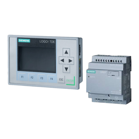
- Page 1 FAM 5 LOGO! Replace / adjust the control and display Operating Instruction English (translation of original instructions) Document No. : 4639760 Follow these instructions for proper and safe use. Keep for future reference.
- Page 2 The contact data of the Documentation Representative is: Günter Harge c/o HYDAC International GmbH, Industriegebiet, 66280 Sulzbach / Saar Germany Telephone: +49 6897 509 1511 Fax: +49 6897 509 1394 E-mail: guenter.harge@hydac.com Print date: 2/3/2022 © HYDAC FILTER SYSTEMS GmbH Subject to technical modifications.
-
Page 3: Table Of Contents
HYDAC FILTER SYSTEMS GMBH Table of Contents Table of Contents General ........................ 4 Target group of the manual ................ 4 Illustrations in the manual................ 5 1.2.1 Illustration on the title page .............. 5 1.2.2 Representation of requirements............ 6 1.2.3 Representation of procedural instructions ......... 6 1.2.4... -
Page 4: General
1 | General HYDAC FILTER SYSTEMS GMBH 1 General Before you use this product for the first time, read this manual at least up to the chapter "Operation". If you would like to carry out maintenance or troubleshooting, you can find the proce- dure in the respective chapters. -
Page 5: Illustrations In The Manual
HYDAC FILTER SYSTEMS GMBH General | 1 1.2 Illustrations in the manual You will find illustrations in this manual. You can find details re- garding these in the following chapters. 1.2.1 Illustration on the title page You will find the following information on the title page of this... -
Page 6: Representation Of Requirements
1 | General HYDAC FILTER SYSTEMS GMBH The document no. with the index (4) is meant for identifying and reordering the manual. The index is incremented every time the manual is revised or changed. The manual contains a table of contents, a list of tables and figures, an index and a glossary. -
Page 7: Representation Of Intermediate Results/Results
HYDAC FILTER SYSTEMS GMBH General | 1 – Rinse the product. 1.2.4 Representation of intermediate results/results In the case of some activities, it is necessary to carry out work steps with intermediate results and end results. Intermediate results are the consequence of activities; they are marked with an indented arrow. -
Page 8: Supplementary Symbols
1 | General HYDAC FILTER SYSTEMS GMBH 1.2.5 Supplementary symbols You will find the following symbols in the manual as additional details: Cross reference to a page / a chapter / a section or u ## another document. Glossary Terms in grey are explained in detail in the glos- sary, a chapter at the end of the manual. -
Page 9: Signal Words And Their Meaning In The General Safety Information
HYDAC FILTER SYSTEMS GMBH General | 1 1.2.7 Signal words and their meaning in the general safety information In these instructions you will find the following signal words: DANGER DANGER – The signal word indicates a hazardous situation with a high level of risk, which, if not avoided, will result lethal or serious injury. -
Page 10: Exclusion Of Liability / Warranty
1 | General HYDAC FILTER SYSTEMS GMBH 1.3 Exclusion of liability / warranty For the warranty provided by us, please refer to our terms of delivery. They are made available to you at the conclusion of the contract at the latest. In addition, you will find these under www.hydac.com ->... -
Page 11: Product- Performance Description
HYDAC FILTER SYSTEMS GMBH Product- Performance description | 2 2 Product- Performance description The LOGO! replacement set is used for the complete replace- ment of defective or faulty controls in the FAM. 2.1 Checking the scope of delivery Before assembly, check the scope of delivery for complete- ness. -
Page 12: Copying The Program
3 | Copying the program HYDAC FILTER SYSTEMS GMBH 3 Copying the program The USB memory stick included in the scope of delivery con- tains different language versions. These can also be loaded to the PLC using a micro SD card, which is also included in the scope of delivery. -
Page 13: Logo! Changing The Plc And Display
HYDAC FILTER SYSTEMS GMBH LOGO! Changing the PLC and display | 4 4 LOGO! Changing the PLC and display To exchange the Siemens Logo! PLC, proceed as follows: ü Switch the unit off and disconnect the main switch. Se- cure the unit against being switched on again. - Page 14 4 | LOGO! Changing the PLC and display HYDAC FILTER SYSTEMS GMBH 6. Loosen the screws (2) and remove the mounting brack- ets (1). 7. Remove the display and the seal ring (3). 8. Insert the new display with seal ring (3) and tighten the screws (2) of the mounting bracket to 0.2 Nm.
-
Page 15: Inserting The Sd Card
HYDAC FILTER SYSTEMS GMBH Inserting the SD card | 5 5 Inserting the SD card To insert the micro SD memory card, proceed as follows: 1x screwdriver 3 x 150 ü Switch the unit off and disconnect the main switch. Se- cure the unit against being switched on again. - Page 16 5 | Inserting the SD card HYDAC FILTER SYSTEMS GMBH O The insertion of the micro SD memory card is complete. 16 / 20 BA FAM5 replace adjust the control and display 4639760 en-us web...
-
Page 17: Setting The Configuration
HYDAC FILTER SYSTEMS GMBH Setting the configuration | 6 6 Setting the configuration After changing the PLC and TDE components, the optional configuration of the unit, e.g. additional sensors or equipment, must be set. The optional sensor system/equipment can be identified, for example, by the type code of the unit. - Page 18 6 | Setting the configuration HYDAC FILTER SYSTEMS GMBH ü Switch on the unit at the main switch. 1. The PLC now automatically copies the program from the micro SD memory card to the PLC. ð When the copying process is complete, the configura- tion menu is displayed.
-
Page 19: Index
HYDAC FILTER SYSTEMS GMBH Index Index Configuration Setting 17 configuration menu Leaving the 17 Opening the 17 Documentation Representative 2 Exclusion of Liability 10 HYDAC General Terms and Conditions 10 Terms of delivery 10 Imprint 2 Manufacturer 2 Publisher 2 Warranty 10... - Page 20 www.hydac.com...
Need help?
Do you have a question about the FAM 5 and is the answer not in the manual?
Questions and answers