
Subscribe to Our Youtube Channel
Related Manuals for HYDAC FILTER SYSTEMS FluidAqua Mobil FAM 10


Summary of Contents for HYDAC FILTER SYSTEMS FluidAqua Mobil FAM 10
- Page 1 FAM 10 FAM 10/15 FluidAqua Mobil Operating and maintenance instructions, part English (translation of original instructions) Keep for future reference. Document no.: 4170097b (Valid for FAM-xx-x-x-x-xx-x-C-x-x)
- Page 2 Imprint FAM 10, Instructions, part 1/2 Page 2 / 72 en-US BEWA FAM10-15 1-2 4170097b en-us 2018-05-23.docx 2018-05-23...
-
Page 3: Imprint
+49 6897 509 1394 E-mail: guenter.harge@hydac.com © HYDAC FILTER SYSTEMS GMBH All rights reserved. No part of this work may be reproduced in any form (print, photocopy or by other means) or processed, duplicated or distributed using electronic systems without the written consent of the publisher. -
Page 4: Table Of Contents
Content Content Imprint ......................3 Documentation Representative ..............3 Content ......................4 Preface ......................6 Technical Support ..................6 Product modification ..................6 Warranty ...................... 6 Using the documentation ................7 General safety information ................8 Hazard symbols ................... 8 Signal words and their meaning in the general safety information and instructions ................... - Page 5 Content Setting up the unit ..................31 Connection overview ................. 32 Notes on pipes and hoses ................. 33 Connecting the inlet (IN) ................. 35 Connecting the outlet (OUT)..............35 Preparing the Vacuum Pump ..............36 Filling up the rotary vane vacuum pump ..........36 Electrical connection of the unit ..............
-
Page 6: Preface
Warranty For the warranty provided by us, please refer to the terms of delivery of HYDAC FILTER SYSTEMS GMBH. You will find these under www.hydac.com -> General terms and conditions. FAM 10, Instructions, part 1/2... -
Page 7: Using The Documentation
Preface Using the documentation Note that the method described for locating specific information does not release you from your responsibility of carefully reading all these instructions prior to starting the unit up for the first time and at regular intervals in the future. What do I want to know? I determine which topic I am looking for. -
Page 8: General Safety Information
General safety information General safety information The unit was built according to the statutory provisions valid at the time of delivery and satisfies current safety requirements. Any residual hazards are indicated by general safety information and instructions and are described in the operating instructions. Observe all safety and warning instructions attached to the unit. -
Page 9: Signal Words And Their Meaning In The General Safety Information And Instructions
General safety information Risk of burns due to hot surfaces Substances that are health hazards or irritants Signal words and their meaning in the general safety information and instructions DANGER DANGER – The signal word indicates a hazardous situation with a high level of risk, which, if not avoided, will result lethal or serious injury. -
Page 10: Structure Of The General Safety Information And Instructions
General safety information Structure of the general safety information and instructions All warning instructions in this manual are highlighted with pictograms and signal words. The pictogram and the signal word indicate the severity of the danger. Warning instructions listed before an activity are laid out as follows: SIGNAL WORD Type and source of danger HAZARD SYMBOL... -
Page 11: Proper/Designated Use
General safety information Proper/Designated Use Use the unit only for the application described in the following. The FAM is for dewatering, filtering and degassing hydraulic and lubricating oils. In addition, it removes free water, emulsified water and a large percentage of the water found in solution. Intended use of the product also extends to the following: •... - Page 12 General safety information Depending on the version (see model code), the FAM may only be used for the following media (see model code): FAM-xx-M- Mineral oil, tested with mineral oil. … Mineral oils acc. to DIN 51524 Gear oils acc. to DIN 51517, 51524 Other hydraulic and lubrication oils which require or are compatible with NBR seals FAM-xx-I-…...
-
Page 13: Improper Use Or Use Deviating From Intended Use
Any use extending beyond this or deviating therefrom shall not be considered intended use. HYDAC Filter Systems GmbH will assume no liability for any damage resulting from such use. This risk is borne solely by the owner. Improper use may result in hazards and/or will damage the unit. Examples of improper use: •... -
Page 14: Qualifications Of Personnel / Target Group
General safety information Qualifications of personnel / target group Persons who work on the power unit must be aware of the associated hazards when using the power unit. Operating and specialist personnel must have read and understood the operating instructions, in particular the general safety information, and applicable regulations before beginning work. - Page 15 General safety information Activity Person Knowledge • Proof of knowledge of cargo Transport / storage Forwarding agent securing instructions • Safe handling/operation of Specialist personnel hoisting and lifting equipment • Safe handling/use of tools Hydraulic / electrical Specialist installation, personnel •...
-
Page 16: Wear Suitable Clothing
Unpacking the unit Wear suitable clothing Loosely worn clothing increases the danger of getting caught or wound up in rotating parts and the danger of getting snagged on projecting parts. You can be severely injured or killed. • Wear close-fitting clothing. •... -
Page 17: Transporting The Unit
Transporting the unit Transporting the unit CAUTION High empty weight (> 300 kg depending on version) Danger of bodily injury ► Use at least 2 persons to shift the mobile unit. NOTICE Using components for pushing/pulling The unit will be damaged. ►... -
Page 18: Transporting With A Crane
Transporting the unit Transporting with a crane The unit has four eyelets on the frame for fastening lifting accessories. NOTICE Unsuitable lifting accessories The unit will be damaged / Components will be damaged / destroyed ► Use only suitable lifting accessories to raise or lash the unit. ►... -
Page 19: Checking The Scope Of Delivery
Checking the scope of delivery Checking the scope of delivery Upon receiving the FAM check it for any damage in transit. The FAM may not be set up and installed unless it is in perfect order. Any damage in transit is to be reported to the forwarding agent or the department in charge immediately;... -
Page 20: Description Of Unit
Description of unit Description of unit The FluidAqua Mobil was developed for the dewatering, filtration and degassing of hydraulic and lubricating oils. It removes free water, emulsified water and a large percentage of the water to be found in solution. The integrated fluid filter ensures an efficient separation of solid particles. -
Page 21: Servicedescription
Description of unit Servicedescription The FluidAqua Mobil is able to dewater authorized fluids down to a water content of less than 100 ppm and transformer oils down to less than 10 ppm. As an approximate guideline, the dimensioning of the FluidAqua Mobil can be defined in accordance with the tank volume. -
Page 22: Description Of Function
Description of function Description of function Option Contamination Sensor * Option Connect up the power unit in bypass flow with the tank that is to be cleaned. After the unit is switched on, the filling pump (3) begins to convey the fluid from the tank through the suction filter (1) into the vacuum column (5) . - Page 23 Description of function Using the AquaSensors (2) installed, the saturation level of the fluid drawn in is measured and displayed on the control panel. The saturation level indicates what percent of maximum possible water is dissolved in the oil. A value of 0% would indicate water-free oil and 100% would mean oil that is completely saturated with water.
-
Page 24: Cleaning In Bypass Flow
Description of function Cleaning in Bypass Flow The FAM is connected with suction and pressure lines to the tank and cleans the medium found there in continuous operation. Purifying and transferring by pumping The FAM is connected to the contaminated oil tank with the suction hose and pumps the fluid into the tank for the purified oil while cleaning it at the same time. -
Page 25: Unit System Components
Description of function Unit system components FAM 10, Instructions, part 1/2 Page 25 / 72 en-US BEWA FAM10-15 1-2 4170097b en-us 2018-05-23.docx 2018-05-23... - Page 26 Description of function Item Designation Suction screen AquaSensor AS1000 Filling pump Non-return valve Vacuum column Heater (Option) Evacuation pump Non-return valve at the outlet (OUT) Fluid filter for separating solid particles Fluid filter drainage Air filter and dryer Needle valve for vacuum setting Pressure sensor for vacuum measurement Vacuum pump Vacuum column level sensor...
-
Page 27: Unit Dimensions
Unit dimensions Unit dimensions The different versions of the FAM series have the following illustrated dimensions. Stationary version FAM 10, Instructions, part 1/2 Page 27 / 72 en-US BEWA FAM10-15 1-2 4170097b en-us 2018-05-23.docx 2018-05-23... -
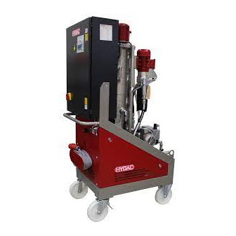
Page 28: Mobile Version
Unit dimensions Mobile version FAM 10, Instructions, part 1/2 Page 28 / 72 en-US BEWA FAM10-15 1-2 4170097b en-us 2018-05-23.docx 2018-05-23... -
Page 29: Hydraulicdiagram
Hydraulicdiagram Hydraulicdiagram FAM 10, Instructions, part 1/2 Page 29 / 72 en-US BEWA FAM10-15 1-2 4170097b en-us 2018-05-23.docx 2018-05-23... - Page 30 Hydraulicdiagram Item Designation Suction screen AquaSensor AS1000 Filling pump Non-return valve Vacuum column Heater (Option) Evacuation pump Non-return valve at the outlet (OUT) Fluid filter for separating solid particles Differential pressure switch for filter monitoring Fluid filter drainage Air filter and dryer Needle valve for vacuum setting Pressure sensor for vacuum measurement Vacuum pump...
-
Page 31: Unit Setup And Connection
Unit setup and connection Unit setup and connection CAUTION Rotary vane vacuum pump Hazardous to health ► Always make sure there is sufficient ventilation in the surrounding area of the unit. Air coming out of the rotary vane vacuum pump can contain particles of vacuum pump oil and/or the fluid. -
Page 32: Connection Overview
Unit setup and connection Connection overview The stationary and mobile FAM versions have different scopes of delivery. The stationary FAM has positions 1-4, while the mobile FAM also has positions 5-8. Item 28L / M36x2 FAM inlet connector (external thread)* Adapter G1 A Adapter (external thread)**... -
Page 33: Notes On Pipes And Hoses
Unit setup and connection Notes on pipes and hoses NOTICE Non-permitted pressure at the inlet IN / outlet OUT Failure malfunction ► Determine the pressure to be anticipated at the inlet/outlet with the prescribed values. Note that the cross-section of the connected hoses/piping must be at least as large as the cross-section of the inlet/outlet port sizes. - Page 34 Unit setup and connection The pressure loss in straight pipes ( ∆ P ) can be calculated as follows: (line) Δp ≈ 6.8 * L / d * Q * V * D Δ = Pressure differential in [bar] = Pipe length [m] = Internal pipe diameter [mm] = Flow rate [l/min] = Kinematic viscosity [mm²/s]...
-
Page 35: Connecting The Inlet (In)
Unit setup and connection Connecting the inlet (IN) The maximum permitted pressure P at the inlet to the FAM can be found e perm in the technical data. Use a negative pressure-resistant, flexible hose or a pipe for the suction-side connection. -
Page 36: Preparing The Vacuum Pump
Unit setup and connection Preparing the Vacuum Pump The rotary vane vacuum pump is not filled with oil at the time the FAM is delivered. A sufficient amount of vacuum pump oil for the initial filling is included in the scope of delivery. NOTICE Operation without vacuum pump oil The rotary vane vacuum pump will be destroyed... -
Page 37: Electrical Connection Of The Unit
Unit setup and connection Electrical connection of the unit DANGER Exposed electrical components in the switch cabinet Danger of fatal injury due to electric shock ► Any work involving the electrical system may only be done by a properly trained, certified electrician. - Page 38 Unit setup and connection A phase sequence relay checks the correct phase sequence after switch-on. In the event of an incorrect phase sequence, error message no. 29 is shown on the control panel. Additional details can be viewed in part 2/2 of the Operating and maintenance instructions.
-
Page 39: Operating Elements On The Fam
Operating Elements on the FAM Operating Elements on the FAM The following operating elements are to be found on the FAM: Item Description Main switch with E-STOP function Alarm signal lamp (yellow) Control panel (for details see Operation and Maintenance Instructions, part 2/2) Needle valve to set the pressure in the vacuum column SensorMonitoring Unit SMU1200 (optional) (See the appropriate operating instructions for details) -
Page 40: Switching On / Switching Off / Commissioning And Error Messages
Switching on / switching off / commissioning and error messages Switching on / switching off / commissioning and error messages Details on switching on/off, commissioning and error messages/troubleshooting can be found in the Operation and Maintenance Instructions, part 2/2. FAM 10, Instructions, part 1/2 Page 40 / 72 en-US BEWA FAM10-15 1-2 4170097b en-us 2018-05-23.docx... -
Page 41: Performing Maintenance
Performing Maintenance Performing Maintenance Before performing any maintenance work, pull out the plug on the FAM and wind up the power cord to prevent the unit from being switched on again. The Unit is to be disconnected from the power supply and protected against being inadvertently switched back on when performing any maintenance, servicing, inspection or repair work. - Page 42 Performing Maintenance spare part) Vacuum pump Checking the oil level Changing oil Replacing the Air De-oiling Element Check and clean the ventilator hood Emptying / filling pump Check and clean the ventilator hood Fluid filter Changing the filter element 48 Emptying and cleaning the filter housing Oil mist separator (optional)
- Page 43 Performing Maintenance with DIN VDE 0702 and/or corresponding national regulation. Measure power consumption of the heater and compare values with type label (applies only to versions with integrated heater) Function Test Testing the oil pan float switch Checking and cleaning the vacuum column level sensor Completely replace all of the hoses after 5 years.
-
Page 44: Function Testing Of The Fault Indicator Lamp
Performing Maintenance Function testing of the fault indicator lamp To perform the function test of the fault indicator lamp, follow these steps: 1. Switch the unit on using the main switch (A). 2. An automatic lamp test is conducted after the unit has been switched on. -
Page 45: Cleaning The Suction Strainer
Cleaning the suction strainer Cleaning the suction strainer NOTICE Operation without a suction strainer The pump will be destroyed ► The unit may not be operated without the suction strainer. ► Clean the suction screen regularly. To protect the pump from coarse contamination particles and other foreign bodies, a dirt trap with a strainer insert is fitted at the pump inlet. -
Page 46: Rotary Vane Vacuum Pump Components
Rotary vane vacuum pump components Rotary vane vacuum pump components Item Designation Oil filler neck Oil drain Oil sight glass Oil separator Suction port connection Gas outlet Safety screw on the plug Plug for the level sensor Level switch in the vacuum pump The following descriptions are in reference to these positions. -
Page 47: Replacing The Air De-Oiling Element
Rotary vane vacuum pump components The vacuum pump must be at operating state temperature when the oil is changed: Put the FAM into operation for 10 minutes. Switch off the FAM at the main switch. Wait until the pressure in the vacuum column has reached the atmospheric pressure (≈... -
Page 48: Replacing The Filter Element On The Fluid Filter
Replacing the filter element on the fluid filter ring. Install the air de-oiling element in such a way that the opening is situated correctly in the holder in the oil separator (g). Ensure that the tip of the screws in the center of the filter spring protrudes ≈... - Page 49 Replacing the filter element on the fluid filter the filter bowl. Release the tensioning clamp (1) on the filter housing and remove it downwards (2). Use a 6 mm (1) Allen wrench. Pull the filter bowl including filter element downwards. FAM 10, Instructions, part 1/2 Page 49 / 72 en-US...
- Page 50 Replacing the filter element on the fluid filter Remove (2) the filter element by turning (1) slightly out of the filter bowl. Dispose of the used filter element in an environmentally correct manner. Clean the inside of the filter bowl of dirt and deposits.
- Page 51 Replacing the filter element on the fluid filter Check the O-ring on the filter bowl for damage. Replace it if necessary. Moisten the O-ring on the filter bowl with the operating medium. Moisten the O-rings on the new filter element with the operating medium. Turning it slightly, press the new filter element down into the mount on the filter bowl.
- Page 52 Replacing the filter element on the fluid filter 10. Push the filter bowl with the filter element up into the mount on the filter head. 11. Slide the tensioning clamp (1) from the bottom over the filter bowl to the top over the bead on the filter bowl / filter head.
-
Page 53: Maintaining The Oil Mist Separator (Optional)
Maintaining the oil mist separator (optional) 13. The filter element change is now complete. After commissioning, check the filtration unit for leaks. Maintaining the oil mist separator (optional) Item Designation Separator head Separator pot Clogging indicator Filling level display FAM 10, Instructions, part 1/2 Page 53 / 72 en-US BEWA FAM10-15 1-2 4170097b en-us 2018-05-23.docx... - Page 54 Maintaining the oil mist separator (optional) The oil mist separator is located between the vacuum column and the vacuum pump. A filter element is used to retain the oil mist and the oil in the oil mist separator and the oil is collected in the separator pot, where it is continuously suctioned off and returned to the vacuum column.
-
Page 55: Replacing The Filter Element On The Oil Mist Separator
Maintaining the oil mist separator (optional) Replacing the filter element on the oil mist separator Proceed as follows to replace the filter element on the oil mist separator: 1. Stop automatic mode. Afterwards, wait ≈ 1 minute, until normal pressure (ambient pressure) has been established in the vacuum chamber. -
Page 56: Testing The Float Switch In The Oil Pan
Testing the float switch in the oil pan Testing the float switch in the oil pan Proceed as follows to test the float switch in the oil pan: Use your fingers to raise the float switch in the oil pan. The unit must switch off and the fault message "Pan overfilled"... -
Page 57: Checking The Level Sensor Of The Vacuum Column
Checking the level sensor of the vacuum column Checking the level sensor of the vacuum column Conditions for the check: Pull out the power plug or deenergize the unit. Replace the installed level sensor Pull out the level sensor connector. Remove the level sensor of the column. - Page 58 Checking the level sensor of the vacuum column 24 V DC Set the multimeter to resistance measurement. Insert the instrument leads on the multimeter into the bushings for resistance measurement. Connect one instrument lead with +24V DC, e.g. with a crocodile clip. Also connect the second instrument lead with the wire from E 0.3;...
-
Page 59: Locating Spare Parts
Locating spare parts Locating spare parts FAM 10 Qty. Designation Part no. Breather filter 0160 MU 003 M 1265765 Suction strainer 1" assy., 635624 consisting of: 1x strainer insert, 250µm 6016797 1x sealing ring 6033969 Vacuum pressure gauge 639989 3/2 directional valve 6014177 Pressure hose, Length = 5 m 6013308... - Page 60 Locating spare parts Vacuum pump oil, 1 liter drum 6018128 Vacuum pump oil, 5 liter drum 6018129 *) available on request FAM 10, Instructions, part 1/2 Page 60 / 72 en-US BEWA FAM10-15 1-2 4170097b en-us 2018-05-23.docx 2018-05-23...
-
Page 61: Taking The Unit Out Of Operation
Taking the unit out of operation Taking the unit out of operation Drain the unit completely, including all of its components, the same way as is done before putting it into storage. Pull out the power plug and securely fasten the hoses and power cord to the unit. -
Page 62: Technical Data
Technical data Technical data Refer to the type label for specific data of the unit. FAM10 FAM10/15 10 l/min @ 50Hz 15 l/min @ 50Hz Flow rate at the inlet (IN) 12 l/min @ 60Hz 18 l/min @ 60Hz 18 l/min @ 50Hz 23 l/min @ 50Hz Flow rate at the outlet (OUT) 22 l/min @ 60Hz... - Page 63 Technical data Sealing material See the model code, page 65 Permitted fluid temperature 10 … 80°C range Permitted ambient 10 … 40°C temperature range Permissable relative humidity maximum 90%, non-condensing Permitted storage temperature 10 … 50 °C range < 100 ppm - Hydraulic and lube oils Achievable residual water <...
-
Page 64: Appendix
Appendix Appendix Contact Customer Service / Service For product information or technical support or if you have comments or suggestions concerning this manual, please contact: HYDAC FILTER SYSTEMS GMBH Phone: +49 6897 509 1174 Fax: +49 6897 509 9046 E-mail: filtersystems@hydac.com... -
Page 65: Model Code
Appendix Model Code A - 05 - R - H - C1 - A - 00 Product FAM = FluidAqua Mobil Filter Size = 10 l/min @ 50 Hz 12 l/min @ 60 Hz 10/15 = 15 l/min @ 50 Hz 18 l/min @ 60 Hz Operating fluid = Mineral oil –... -
Page 66: Explanation Of Terms And Abbreviations
Appendix Explanation of terms and abbreviations An explanation of terms and abbreviations follows below: %Sat. % Water saturation, degree of saturation % saturation % Water saturation, degree of saturation °C Degrees Celsius °F Degrees Fahrenheit abs. Absolute (e.g. in pressure specifications) Alternating current Air Bleed Ventilation / air bleed port... - Page 67 Appendix The fluid is fire resistant. HFD-R Phosphoric acid ester Mineral oil–based hydraulic fluids with active ingredients for increasing rust protection, with high-pressure additives and aging resistance (also HLP acc. to DIN 51 524, part 2) Inlet INLET Inlet Classification of the solid particle contamination. Kilopascal Meter Maximum...
-
Page 68: Index
Appendix Index accident prevention 10 Gear pump 62 ambient temperature 21, 31, 63 AquaSensor 26, 30, 41, 42, 44, 65, 66 ATEX 66 Hazard symbol 8, 10 Heater 26, 30, 65 HFD 12, 66, 67 Breather filter 59 Imprint 3 care 3, 6, 18 IN 26, 30, 33, 35, 41, 62, 67 Changing the filter element 42... - Page 69 Appendix operating 6, 7, 8, 12, 13, 14, 15, 24, 36, 39, 44, 46, Suction hose 20, 32, 59 47, 48, 51, 66 Suction port connection 46 Operation 13, 15, 36, 39, 40, 45 Suction screen 26, 30 Operations control 15 switching off 40 OUT 26, 30, 33, 35, 62, 67 switching on 40...
- Page 72 HYDAC FILTER SYSTEMS GMBH Industriegebiet Postfach 1251 66280 Sulzbach/Saar 66273 Sulzbach/Saar Germany Germany Tel: +49 6897 509 01 Central Fax: +49 6897 509 9046 Technology Fax: +49 6897 509 577 Sales Internet: www.hydac.com E-mail: filtersystems@hydac.com...
Need help?
Do you have a question about the FluidAqua Mobil FAM 10 and is the answer not in the manual?
Questions and answers