
Related Manuals for Beckhoff KL3214


Summary of Contents for Beckhoff KL3214
- Page 1 Documentation KL3214 Four-channel HD input terminal for 3-wire connection of resistance sensors Version: 1.2.0 Date: 2019-09-24...
-
Page 3: Table Of Contents
Table of contents Table of contents 1 Foreword .............................. 5 Notes on the documentation...................... 5 Safety instructions .......................... 6 Documentation Issue Status...................... 7 Beckhoff Identification Code (BIC) .................... 7 2 Product overview............................. 10 Introduction ............................ 10 Technical data .......................... 11 3 Mounting and wiring.......................... 12 Instructions for ESD protection ...................... 12 Installation on mounting rails ...................... 12... - Page 4 Table of contents Version: 1.2.0 KL3214...
-
Page 5: Foreword
EP1590927, EP1789857, EP1456722, EP2137893, DE102015105702 with corresponding applications or registrations in various other countries. ® EtherCAT is registered trademark and patented technology, licensed by Beckhoff Automation GmbH, Germany. Copyright © Beckhoff Automation GmbH & Co. KG, Germany. The reproduction, distribution and utilization of this document as well as the communication of its contents to others without express authorization are prohibited. -
Page 6: Safety Instructions
All the components are supplied in particular hardware and software configurations appropriate for the application. Modifications to hardware or software configurations other than those described in the documentation are not permitted, and nullify the liability of Beckhoff Automation GmbH & Co. KG. Personnel qualification This description is only intended for trained specialists in control, automation and drive engineering who are familiar with the applicable national standards. -
Page 7: Documentation Issue Status
00 - hardware version 00 Beckhoff Identification Code (BIC) The Beckhoff Identification Code (BIC) is increasingly being applied to Beckhoff products to uniquely identify the product. The BIC is represented as a Data Matrix Code (DMC, code scheme ECC200), the content is based on the ANSI standard MH10.8.2-2016. -
Page 8: Fig. 1 Bic As Data Matrix Code (Dmc, Code Scheme Ecc200)
The following information is contained: Item Type of Explanation Data Number of digits Example information identifier incl. data identifier Beckhoff order Beckhoff order number 1P 1P072222 number Beckhoff Traceability Unique serial number, SBTNk4p562d7 Number (BTN) see note below Article description Beckhoff article 1KEL1809 description, e.g. - Page 9 Example of composite information from item 1 to 4 and 6. The data identifiers are marked in red for better display: An important component of the BIC is the Beckhoff Traceability Number (BTN, item no. 2). The BTN is a unique serial number consisting of eight characters that will replace all other serial number systems at Beckhoff in the long term (e.g.
-
Page 10: Product Overview
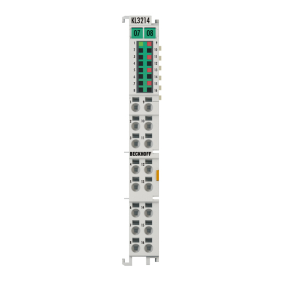
Product overview Introduction Fig. 2: KL3214-0000 The KL3214 analog HD input terminal allows four resistance sensors to be connected directly on a width of 12 mm. The Bus Terminal's circuitry can handle sensors using the 3-wire technique. A microprocessor handles linearization across the whole temperature range, which is freely selectable. -
Page 11: Technical Data
Product overview Technical data Technical data KL3214-0000 Number of inputs Sensor types PT100/200/500/1000, Ni100/120/1000, KTY sensors, Potentiometer (10 Ω … 1.2/4 kΩ) Connection technology 3-wire Measuring range Pt sensors -200°C ... +850°C Ni sensors -60°C ... +250°C Measuring current typ. 0.5 mA (load-dependent) Resolution 0.1℃... -
Page 12: Mounting And Wiring
• Each assembly must be terminated at the right hand end with a KL9010 bus end terminal, to ensure the protection class and ESD protection. Fig. 3: Spring contacts of the Beckhoff I/O components Installation on mounting rails WARNING... -
Page 13: Fig. 4 Attaching On Mounting Rail
To mount the mounting rails with a height of 7.5 mm under the terminals and couplers, you should use flat mounting connections (e.g. countersunk screws or blind rivets). KL3214 Version: 1.2.0... -
Page 14: Fig. 5 Disassembling Of Terminal
EL91xx, EL92xx) interrupt the power contacts and thus represent the start of a new supply rail. PE power contact The power contact labeled PE can be used as a protective earth. For safety reasons this contact mates first when plugging together, and can ground short-circuit currents of up to 125 A. Version: 1.2.0 KL3214... -
Page 15: Installation Instructions For Enhanced Mechanical Load Capacity
Vibration 10 frequency runs in 3 axes 6 Hz < f < 60 Hz displacement 0.35 mm, constant amplitude 60.1 Hz < f < 500 Hz acceleration 5 g, constant amplitude Shocks 1000 shocks in each direction, in 3 axes 25 g, 6 ms KL3214 Version: 1.2.0... -
Page 16: Connection
Standard wiring (ELxxxx / KLxxxx) Fig. 7: Standard wiring The terminals of ELxxxx and KLxxxx series have been tried and tested for years. They feature integrated screwless spring force technology for fast and simple assembly. Version: 1.2.0 KL3214... -
Page 17: Fig. 8 Pluggable Wiring
Ultrasonically "bonded" (ultrasonically welded) conductors Ultrasonically “bonded" conductors It is also possible to connect the Standard and High Density Terminals with ultrasonically "bonded" (ultrasonically welded) conductors. In this case, please note the tables concerning the wire-size width below! KL3214 Version: 1.2.0... -
Page 18: Wiring
The cables are released, as usual, using the contact release with the aid of a screwdriver. See the following table for the suitable wire size width. Version: 1.2.0 KL3214... -
Page 19: Shielding
Wire size width (conductors with a wire end sleeve) 0.14 ... 0.75 mm Wire size width (ultrasonically “bonded" conductors) only 1.5 mm Wire stripping length 8 ... 9 mm 3.4.3 Shielding Shielding Encoder, analog sensors and actors should always be connected with shielded, twisted paired wires. KL3214 Version: 1.2.0... -
Page 20: Connection And Led Displays
Mounting and wiring Connection and LED displays Fig. 11: KL3214 - terminal points and LEDs Connection - KL3214 Terminal point Comment Input +R1 Input RL1 Input +R2 Input RL2 Input +R3 Input RL3 Input +R4 Input RL4 Input –R1 n.c. reserved Input –R2... -
Page 21: Ks2000 Configuration Software
Fieldbus Box modules with the aid of which settings can be modified easily. Alternatively, you have full access to all internal registers of the bus couplers and intelligent terminals. Refer to the register description for the meanings of the registers. KL3214 Version: 1.2.0... -
Page 22: Parameterization With Ks2000
Click on the Login button. The configuration software will now load the information for the connected fieldbus station. In the example shown, this is • a BK9000 Bus Coupler for Ethernet • a KL1xx2 digital input terminal • a KL3214 multimeter terminal • a KL9010 bus end terminal Version: 1.2.0 KL3214... -
Page 23: Fig. 13 Display Of The Fieldbus Station In Ks2000
In the tree structure of the left-hand window, click on the plus-sign next to the terminal whose parameters you wish to change (item 2 in the example). Fig. 14: KS2000 tree branch for channel 1 of the KL3214 For the KL3214, the branches Register, Settings and ProcData are displayed: KL3214 Version: 1.2.0... -
Page 24: Register
• A dialog mask for the parameterization of the KL3214 can be found under Settings [} 26]. • ProcData displays the KL3214 process data. Register You can access the registers of the KL3214 directly under Register.– The meaning of the register is explained in the register overview. Version: 1.2.0... -
Page 25: Fig. 15 Register View In Ks2000
KS2000 Configuration software Fig. 15: Register view in KS2000 KL3214 Version: 1.2.0... -
Page 26: Settings
KS2000 Configuration software Settings The dialog mask for the parameterization of the KL3214 can be found under Settings. Fig. 16: Parameterization with the KS2000 configuration software Operation mode • User scaling active (R32.0 [} 35]) You can activate user scaling here (default: deactivated). -
Page 27: Sample Program For Kl Register Communication Via Ethercat On Kl3314 Exemplary
R32 and user scaling offset and gain (R33/ R34) similar as per KS2000. Fig. 17: Settings of KL3314 via visualisation of TwinCAT 3 At least following configuration setup shall be present: [coupler (e.g. BK1120) or embedded PC] + KL3314 + KL9010. KL3214 Version: 1.2.0... -
Page 28: Fig. 18 Opening The *. Tnzip Archive
KS2000 Configuration software Download: https://infosys.beckhoff.com/content/1033/kl3214/Resources/zip/5996114571.zip Preparations for starting the sample programs (tnzip file / TwinCAT 3) • Click on the download button to save the Zip archive locally on your hard disk, then unzip the *.tnzip archive file in a temporary folder. - Page 29 "Change NetId..." have to be selected. The first 4 numbers of the NetId of the target computer have to be entered; the both last values are 4.1 usually. Example: ◦ NetId of project: myComputer (123.45.67.89.1.1) ◦ Entry via „Change NetId...“: 123.45.67.89.4.1 KL3214 Version: 1.2.0...
-
Page 30: Access From The User Program
Measuring range exceeded, overrange or underrange; the Error LED lights up or conversion error or invalid measuring range SB.5 reserved SB.4 reserved SB.3 reserved SB.2 reserved SB.1 overrange 1 Electrical measuring range exceeded SB.0 underrange 1 Electrical measuring range undershot Version: 1.2.0 KL3214... -
Page 31: Register Communication
SB.6 SB.5 SB.4 SB.3 SB.2 SB.1 SB.0 Name RegAccess R/W Reg. no. Name Description SB.7 RegAccess 1 Acknowledgement for register access SB.6 Read access SB.5 Reg. no. Number of the register that was read or written. SB.0 KL3214 Version: 1.2.0... -
Page 32: Register Overview
User scaling: Offset 0x0000 SEEROM R33 [} 36] User scaling: Gain 0x0100 SEEROM R34 [} 36] reserved 0x0000 reserved 0x0000 Filter setting 0x0000 SEEROM R37 [} 36] Compensation for the line resistance 0x0000 SEEROM R38 [} 36] reserved 0x0000 … … reserved 0x0000 Version: 1.2.0 KL3214... -
Page 33: Register Description
Access from the user program Register description The following registers are used for parameterization of the KL3214. They can be read or written via the register communication with the aid of control, status and data bytes. • R0: ADC raw value RTD Raw value of the A/D converter (X ). - Page 34 This register contains the vendor calibration gain for RL. • R29: Terminal type, special version Register R29 contains the special designation of the KL3214-0000 terminal: 0x0000 (0000 • R31: Code word register ◦ If you write values into the user registers without first entering the user code word (0x1235) into the code word register, the terminal will not accept the supplied data.
- Page 35 Siemens S5 Format enabled R32.3 reserved R32.2 enWdTimer Watchdog timer is not active Watchdog timer is active (the watchdog is triggered if no process data are received for 100 ms) R32.1 reserved R32.0 enUserScal- User scaling deactivated User scaling activated KL3214 Version: 1.2.0...
-
Page 36: Examples Of Register Communication
• The terminal returns the value of the control byte as a receipt in the status byte. • The terminal returns the firmware version 0x3341 in the input data word (byte 1 and byte 2). This is to be interpreted as an ASCII code: Version: 1.2.0 KL3214... -
Page 37: Example 2: Writing To An User Register
• The output data word (byte 1 and byte 2) has no meaning during read access. Input Data (answer of the bus terminal) Byte 0: Status byte Byte 1: DataIN1, high byte Byte 2: DataIN1, low byte 0x9F (1001 1111 0x12 0x35 KL3214 Version: 1.2.0... - Page 38 • The output data word (byte 1 and byte 2) has no meaning during read access. Input Data (answer of the bus terminal) Byte 0: Status byte Byte 1: DataIN1, high byte Byte 2: DataIN1, low byte 0xA0 (1010 0000 0x00 0x02 Explanation: Version: 1.2.0 KL3214...
- Page 39 • The terminal returns a value as a receipt in the status byte that differs only in bit 0.6 from the value of the control byte. • The input data word (byte 1 and byte 2) is of no importance after the write access. Any values still displayed are invalid! KL3214 Version: 1.2.0...
-
Page 40: Process Image
Access from the user program Process image Complex mapping The following 12 bytes are transferred bi-directionally between KL3214 and control: Byte offset (without Byte offset (with Format Input data Output data word alignment*) word alignment*) Byte Status byte 0 (SB0) -
Page 41: Mapping
Default mapping for: PROFIBUS, Interbus Conditions Word offset High byte Low byte Complex evaluation: no Ch0 D0 Ch0 D1 Ch1 D0 Ch1 D1 Motorola format: yes Ch2 D0 Ch2 D1 Word alignment: don't care Ch3 D0 Ch3 D1 KL3214 Version: 1.2.0... - Page 42 CANopen, CANCAL, DeviceNet, ControlNet, Modbus, RS232, RS485 Conditions Word offset High byte Low byte Complex evaluation: no Ch0 D1 Ch0 D0 Ch1 D1 Ch1 D0 Motorola format: no Ch2 D1 Ch2 D0 Word alignment: don't care Ch3 D1 Ch3 D0 Version: 1.2.0 KL3214...
-
Page 43: Appendix
Beckhoff's branch offices and representatives Please contact your Beckhoff branch office or representative for local support and service on Beckhoff products! The addresses of Beckhoff's branch offices and representatives round the world can be found on her internet pages: http://www.beckhoff.com You will also find further documentation for Beckhoff components there. - Page 44 Fig. 12 KS2000 configuration software....................Fig. 13 Display of the fieldbus station in KS2000 ..................Fig. 14 KS2000 tree branch for channel 1 of the KL3214................ Fig. 15 Register view in KS2000......................Fig. 16 Parameterization with the KS2000 configuration software ............
Need help?
Do you have a question about the KL3214 and is the answer not in the manual?
Questions and answers