Sign In
Upload
Download
Table of Contents
Contents
Add to my manuals
Delete from my manuals
Share
URL of this page:
HTML Link:
Bookmark this page
Add
Manual will be automatically added to "My Manuals"
Print this page
×
Bookmark added
×
Added to my manuals
Manuals
Brands
Beckhoff Manuals
Touch terminals
KL320 Series
Documentation
Beckhoff KL320 Series Documentation
Analog input terminals for pt100 (rtd) or ntc10k
Hide thumbs
Also See for KL320 Series
:
Documentation
(58 pages)
1
2
3
4
5
6
7
8
9
10
11
12
13
14
15
16
17
18
19
20
21
22
23
24
25
26
27
28
29
30
31
32
33
34
35
36
37
38
39
40
41
42
43
44
45
46
47
48
49
50
51
52
53
54
page
of
54
Go
/
54
Contents
Table of Contents
Bookmarks
Table of Contents
Table of Contents
1 Foreword
Notes on the Documenation
Safety Instructions
Documentation Issue Status
2 Product Overview
Introduction
Fig. 1 KL3201
Fig. 3 KL3204-0000
Fig. 4 KL3204-0030
Technical Data
Basic Function Principles
Fig. 5 Data Flow of the Kl320X
3 Mounting and Wiring
Installation on Mounting Rails
Fig. 6 Attaching on Mounting Rail
Fig. 7 Disassembling of Terminal
Fig. 8 Power Contact on Left Side
Installation Instructions for Enhanced Mechanical Load Capacity
Connection System
Fig. 9 Standard Wiring
Fig. 10 Pluggable Wiring
Fig. 11 High Density Terminals
Fig. 12 Mounting a Cable on a Terminal Connection
Connection and LED Description
Fig. 13 KL3201 - Connection and Leds
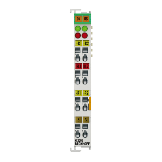
Fig. 2 KL3202
Fig. 14 KL3202 - Connection and Leds
Fig. 15 KL3204/ KL3204-0030 - Connection and Leds
ATEX - Special Conditions (Standard Temperature Range)
ATEX - Special Conditions (Extended Temperature Range)
ATEX Documentation
4 KS2000 Configuration Software
KS2000 - Introduction
Fig. 16 KS2000 Configuration Software
5 Access from the User Program
Mapping
Kl3201
Kl3204, Kl3204-0030
Terminal Configuration
Fig. 17 Mapping BK2000
Fig. 18 Mapping BK3000
Fig. 19 Mapping BK4000
Register Overview
General Description of Registers
Process Variables
Type Register
Manufacturer Parameters
User Parameters
Extended User Area
Terminal-Specific Register Description
Process Variables
Manufacturer Parameters
User Parameters
Output Format
Control and Status Byte
Control Byte for Process Data Exchange
Status Byte for Process Data Exchange
Compensation
Default Setting of the Registers
KL3202 as Resistance Input 0 to 1 Kω
Register Communication
Register Access Via Process Data Exchange
Fig. 20 Register-Modus Control Byte
Example 1
Example 2
6 Twincat
Programming
Function Block Fb_Kl320Xconfig
7 Appendix
Support and Service
List of Illustrations
Advertisement
Quick Links
1
Fig. 3 Kl3204-0000
2
Fig. 4 Kl3204-0030
3
Fig. 2 Kl3202
4
Fig. 14 Kl3202 - Connection and Leds
5
Fig. 15 Kl3204/ Kl3204-0030 - Connection and Leds
Download this manual
Documentation
KL320x
Analog Input Terminals for Pt100 (RTD) or NTC10K
Version:
Date:
4.4
2019-09-10
Table of
Contents
Previous
Page
Next
Page
1
2
3
4
5
Advertisement
Chapters
Table of Contents
4
List of Illustrations
54
Table of Contents
Need help?
Do you have a question about the KL320 Series and is the answer not in the manual?
Ask a question
Questions and answers
Related Manuals for Beckhoff KL320 Series
Touch terminals Beckhoff KS320 Series Documentation
Analog input terminals for pt100 (rtd) or ntc10k (58 pages)
Touch terminals Beckhoff KL3214 Documentation
Four-channel hd input terminal for 3-wire connection ofresistance sensors. (44 pages)
Touch terminals Beckhoff KL3222 Documentation
2 channel accurate input terminals for pt100 (rtd) (43 pages)
Touch terminals Beckhoff KS3222 Documentation
2 channel accurate input terminals for pt100 (rtd) (45 pages)
Touch terminals Beckhoff KL3201 Documentation
Analog input terminals for pt100 (rtd) or ntc10k (54 pages)
Touch terminals Beckhoff KL3202 Documentation
Analog input terminals for pt100 (rtd) or ntc10k (54 pages)
Touch terminals Beckhoff KL3208-0010 Documentation
Eight channel input terminals for pt1000, ni1000, ntc (49 pages)
Touch terminals Beckhoff KL3208 Manual
Eight channel input terminals for pt1000, ni1000, ntc (56 pages)
Touch terminals Beckhoff KL3228 Manual
Eight channel input terminals for pt1000, ni1000, ntc (56 pages)
Touch terminals Beckhoff KL3356 Documentation
Accurate 1 channel terminal for resistance bridges (55 pages)
Touch terminals beckhoff KL3444 Documentation
Four and eight channel analog input terminals (58 pages)
Touch terminals Beckhoff KL3314 Documentation
Single, dual- and four-channel analog imput terminals for thermocouples (51 pages)
Touch terminals Beckhoff KL3403 Series Documentation
3-phase power measurement terminals (65 pages)
Touch terminals Beckhoff KL3132 Manual
Two channel accurate analog terminals (63 pages)
Touch terminals Beckhoff KL3172 Manual
Two channel accurate analog terminals (63 pages)
Touch terminals Beckhoff KL3182 Manual
Two channel accurate analog terminals (63 pages)
This manual is also suitable for:
Kl3201
Kl3202
Kl3204-0000
Kl3204-0030
Table of Contents
Print
Rename the bookmark
Delete bookmark?
Delete from my manuals?
Login
Sign In
OR
Sign in with Facebook
Sign in with Google
Upload manual
Upload from disk
Upload from URL


Need help?
Do you have a question about the KL320 Series and is the answer not in the manual?
Questions and answers