
Related Manuals for Beckhoff KL3403 Series


Summary of Contents for Beckhoff KL3403 Series
- Page 1 Documentation KL3403 3-Phase Power Measurement Terminals Version: 3.1.0 Date: 2019-09-20...
-
Page 3: Table Of Contents
Table of contents Table of contents 1 Foreword .............................. 5 Notes on the documentation...................... 5 Safety instructions .......................... 6 Documentation issue status ...................... 7 Beckhoff Identification Code (BIC) .................... 9 2 Product overview............................. 12 Introduction ............................ 12 LEDs .............................. 13 Basic function principles ........................ 14 Technical data .......................... 19 Current transformer ......................... 20 3 Mounting and wiring.......................... 22... - Page 4 Table of contents Version: 3.1.0 KL3403...
-
Page 5: Foreword
EP1590927, EP1789857, EP1456722, EP2137893, DE102015105702 with corresponding applications or registrations in various other countries. ® EtherCAT is registered trademark and patented technology, licensed by Beckhoff Automation GmbH, Germany. Copyright © Beckhoff Automation GmbH & Co. KG, Germany. The reproduction, distribution and utilization of this document as well as the communication of its contents to others without express authorization are prohibited. -
Page 6: Safety Instructions
All the components are supplied in particular hardware and software configurations appropriate for the application. Modifications to hardware or software configurations other than those described in the documentation are not permitted, and nullify the liability of Beckhoff Automation GmbH & Co. KG. Personnel qualification This description is only intended for trained specialists in control, automation and drive engineering who are familiar with the applicable national standards. -
Page 7: Documentation Issue Status
Foreword Documentation issue status Version Comment 3.1.0 • Design of the safety instructions adapted to IEC 82079-1 • Example program added to chapter “KS2000 Configuration software“ • Description of KL3403-0333 added • KL3403-0021 deleted • Technical data updated • Chapter Instructions for ESD protection added 3.0.0 •... - Page 8 Foreword Version Comment 2.0.0 • Permitted ambient temperature range for KL3403-0000 and KL3403-0010 extended • Technical data updated • Chapter Basic function principles expanded 1.9.0 • UL notes updated • Technical data updated 1.8.0 • UL notes added • Technical data updated 1.7.0 •...
-
Page 9: Beckhoff Identification Code (Bic)
03 - hardware version 03 Beckhoff Identification Code (BIC) The Beckhoff Identification Code (BIC) is increasingly being applied to Beckhoff products to uniquely identify the product. The BIC is represented as a Data Matrix Code (DMC, code scheme ECC200), the content is based on the ANSI standard MH10.8.2-2016. - Page 10 The following information is contained: Item Type of Explanation Data Number of digits Example information identifier incl. data identifier Beckhoff order Beckhoff order number 1P 1P072222 number Beckhoff Traceability Unique serial number, SBTNk4p562d7 Number (BTN) see note below Article description Beckhoff article 1KEL1809 description, e.g.
- Page 11 Example of composite information from item 1 to 4 and 6. The data identifiers are marked in red for better display: An important component of the BIC is the Beckhoff Traceability Number (BTN, item no. 2). The BTN is a unique serial number consisting of eight characters that will replace all other serial number systems at Beckhoff in the long term (e.g.
-
Page 12: Product Overview
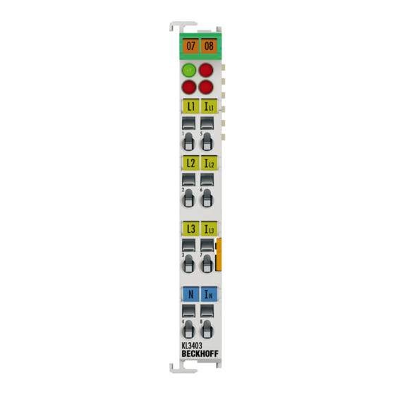
Product overview Product overview Introduction Fig. 2: KL3403 The 3-phase Power Measurement Terminal KL3403 enables the measurement of the electrical data of a three-phase supply network: • The voltage is measured via the connection of the network at the terminal points L1, L2, L3 and N. •... -
Page 13: Leds
Product overview Versions Several variants of the KL3403 are available. Name Comment Nominal value KL3403-0000 Standard version 1 A KS3403-0000 KL3403-0026 1 A Like KL3403-0000, but without EMC leakage capacitor between terminal points 4/8 [} 29] and the grounding contact for the mounting rail. KL3403-0010 Power measurement terminal with higher-capacity current circuits. -
Page 14: Basic Function Principles
Product overview Basic function principles Measuring principle The KL3403 works with 6 analog/digital converters for recording the current and voltage values of all 3 phases. The values are sampled with a time grid of approximately 16 µs. Recording and processing is synchronous and identical for the 3 phases. The signal processing for one phase is described below. - Page 15 Product overview The default setting for the measuring interval is 50 ms, corresponding to 2.5 T in a 50 Hz mains system and 3 T in a 60 Hz mains system. Experience shows that this is a good compromise between measuring speed and stability. Deviations from this value are only advisable in the event of particular measurement requirements (e.g. high measuring speed, low signal frequencies or special current curves).
- Page 16 Product overview The active power is smaller than the apparent power. S: Apparent power P: Active power Q: Reactive power φ: Phase shift angle curves with phase shift angle φ Fig. 6: u curves with phase shift angle φ Version: 3.1.0 KL3403...
- Page 17 Product overview In this context, further parameters of the mains system and its consumers are significant: • apparent power S • reactive power Q • power factor cos φ The KL3403 determines the following values: • active power P • effective voltage U •...
- Page 18 Product overview Fig. 7: Four-quadrant representation of active/reactive power in motor and generator mode Peak current measurement A distinction has to be made between the peak instantaneous value and the peak rms value. The peak rms value always refers to the peak value within the specified measuring interval. Frequency measurement The KL3403 can measure the frequency of the input signals at the voltage circuits (L1, L2, L3).
-
Page 19: Technical Data
Product overview Technical data Technical data KL3403-... KS3403-... 0000 0010 0014 0020 0022 0025 0026 0333 Measured values U, I U, I U, I U, I U, I U, I Calculated parameters Active power, energy, power factor (cosj) Measuring voltage max. -
Page 20: Current Transformer
Product overview Current transformer In principle, the choice of current transformer for the KL3403 is not critical. The internal resistance within the current circuit of the KL3403 is so small that it is negligible for the calculation of the total resistances of the current loop. - Page 21 Product overview On the voltage measurement side, a KL3403 is equipped with a protection impedance of 500 kΩ. If the neutral conductor is not connected and only one connection on the side of the voltage measurement is live, the resulting voltage against earth in a 3-phase system with a phase-to-phase voltage of 400 V is 230 V This should also be measured on the side of the current measurement using a multimeter with an internal resistance of 10 MΩ, which does not represent an insulation fault.
-
Page 22: Mounting And Wiring
• Each assembly must be terminated at the right hand end with a KL9010 bus end terminal, to ensure the protection class and ESD protection. Fig. 8: Spring contacts of the Beckhoff I/O components Installation on mounting rails WARNING... - Page 23 Mounting and wiring Assembly Fig. 9: Attaching on mounting rail The bus coupler and bus terminals are attached to commercially available 35 mm mounting rails (DIN rails according to EN 60715) by applying slight pressure: 1. First attach the fieldbus coupler to the mounting rail. 2.
- Page 24 Mounting and wiring Disassembly Fig. 10: Disassembling of terminal Each terminal is secured by a lock on the mounting rail, which must be released for disassembly: 1. Pull the terminal by its orange-colored lugs approximately 1 cm away from the mounting rail. In doing so for this terminal the mounting rail lock is released automatically and you can pull the terminal out of the bus terminal block easily without excessive force.
-
Page 25: Connection
Mounting and wiring Fig. 11: Power contact on left side NOTE Possible damage of the device Note that, for reasons of electromagnetic compatibility, the PE contacts are capacitatively coupled to the mounting rail. This may lead to incorrect results during insulation testing or to damage on the terminal (e.g. disruptive discharge to the PE line during insulation testing of a consumer with a nominal voltage of 230 V). - Page 26 Mounting and wiring Standard wiring (ELxxxx / KLxxxx) Fig. 12: Standard wiring The terminals of ELxxxx and KLxxxx series have been tried and tested for years. They feature integrated screwless spring force technology for fast and simple assembly. Pluggable wiring (ESxxxx / KSxxxx) Fig. 13: Pluggable wiring The terminals of ESxxxx and KSxxxx series feature a pluggable connection level.
-
Page 27: Wiring
Mounting and wiring Wiring HD Terminals The High Density (HD) Terminals of the ELx8xx and KLx8xx series doesn't support pluggable wiring. Ultrasonically "bonded" (ultrasonically welded) conductors Ultrasonically “bonded" conductors It is also possible to connect the Standard and High Density Terminals with ultrasonically "bonded"... - Page 28 Mounting and wiring Terminal housing ELxxxx, KLxxxx ESxxxx, KSxxxx Wire size width (single core wires) 0.08 ... 2.5 mm 0.08 ... 2.5 mm Wire size width (fine-wire conductors) 0.08 ... 2.5 mm 0,08 ... 2.5 mm Wire size width (conductors with a wire end sleeve) 0.14 ...
-
Page 29: Connection
Mounting and wiring 3.3.3 Connection WARNING Risk of injury through electric shock and damage to the device! Bring the Bus Terminals system into a safe, de-energized state before starting mounting, disassembly or wiring of the Bus Terminals! Fig. 16: Connection Terminal point No.: Connection for Comment Phase L1... -
Page 30: Application Examples
BKxxxx, BCxxxx, BXxxxx, LCxxxx, CXxxxx, KLxxxx, KSxxxx or KMxxxx from Beck- hoff. cULus verification For the cULus verification, the Beckhoff I/O system only examined for risk of fire or electric shock (in accordance with UL508 and CSA C22.2 No. 142). Phase voltage according to UL specifications 300 V max. -
Page 31: Application Examples For Alternating Current
Mounting and wiring 3.4.1 Application examples for alternating current WARNING Risk of injury through electric shock and damage to the device! Bring the Bus Terminals system into a safe, de-energized state before starting mounting, disassembly or wiring of the Bus Terminals! CAUTION Operate the current transformer as intended! Please note that many manufacturers do not permit their current transformers to be operated in no-load... - Page 32 Mounting and wiring Polarity of the current transformers If negative power values are measured on a circuit, please check whether the associated current transformer circuit is connected correctly. Current measurement on a motor CAUTION Make sure terminal point N is zeroed or grounded! If you do not connect the terminal point N with the neutral conductor of your mains supply (e.g. if the KL3403 is used purely for current measurements), terminal point N should be earthed, in order to avoid dangerous overvoltages in the event of a current transformer fault!
-
Page 33: Application Example For Dc
Mounting and wiring 3.4.2 Application example for DC WARNING Risk of injury through electric shock and damage to the device! Bring the Bus Terminals system into a safe, de-energized state before starting mounting, disassembly or wiring of the Bus Terminals! Switch off the DC filter for DC measurements Switch off the DC filters for the KL3403 (using the configuration software KS2000 [} 41] or the reg- ister communication (register R32.4 [} 54])) for measuring direct voltage and DC. -
Page 34: Application Example With Frequency Converter
Mounting and wiring Fig. 19: Application example - power measurement at a fieldbus station 3.4.3 Application example with frequency converter WARNING Risk of injury through electric shock and damage to the device! Bring the Bus Terminals system into a safe, de-energized state before starting mounting, disassembly or wiring of the Bus Terminals! The example illustrates power measurement at several three-phase motors that are controlled by a frequency converter (AC converter), e.g. at a conveyor system. - Page 35 Mounting and wiring Fig. 20: Application example with frequency converter The electrical isolation of the three-phase-transformer (Yy0) operated by the voltage circuit of the power measurement terminals enables measurement after the frequency converter. Measuring error in the lower frequency range If the power measurement takes place after the frequency converter, a larger measuring error is possible in the lower frequency range, particularly for voltage measurement.
-
Page 36: Application Example For Kl3403-0014
Mounting and wiring 3.4.4 Application example for KL3403-0014 WARNING Risk of injury through electric shock and damage to the device! Bring the Bus Terminals system into a safe, de-energized state before starting mounting, disassembly or wiring of the Bus Terminals! The KL3403-0014 has no internal shunts for current measurement. - Page 37 Mounting and wiring Dimensioning of the shunts A voltage drop of 60 mV / x A is typically indicated for the shunts. Examples Nominal value of the shunt 60 mV / 1 A 60 mV / 25 A 60 mV / 100 A Sample current 1 A 25 A 100 A Current output value of the terminal 25000 (0x61A8) 25000 (0x61A8)
-
Page 38: Ks2000 Configuration Software
KS2000 Configuration Software KS2000 Configuration Software KS2000 - Introduction The KS2000 configuration software permits configuration, commissioning and parameterization of bus couplers, of the affiliated bus terminals and of Fieldbus Box Modules. The connection between bus coupler / Fieldbus Box Module and the PC is established by means of the serial configuration cable or the fieldbus. Fig. 22: KS2000 configuration software Configuration You can configure the Fieldbus stations with the Configuration Software KS2000 offline. -
Page 39: Parameterization With Ks2000
KS2000 Configuration Software Commissioning The KS2000 software facilitates commissioning of machine components or their fieldbus stations: Configured settings can be transferred to the fieldbus modules by means of a download. After a login to the terminal station, it is possible to define settings in couplers, terminals and Fieldbus Box modules directly online. The same high-level dialogs and register access are available for this purpose as in the configuration phase. - Page 40 KS2000 Configuration Software Fig. 23: Display of the fieldbus station in KS2000 The left-hand KS2000 window displays the terminals of the fieldbus station in a tree structure. The right-hand KS2000 window contains a graphic display of the fieldbus station terminals. In the tree structure of the left-hand window, click on the plus-sign next to the terminal whose parameters you wish to change (item 2 in the example).
-
Page 41: Settings
KS2000 Configuration Software For each of the three channels, the branches Register, Settings and ProcData are displayed: • Register enables direct access to the channel registers. • The dialog mask for the parameterization of the KL3403 can be found under Settings [} 41]. •... - Page 42 KS2000 Configuration Software Watchdog timer active (R32 [} 54].2) You can deactivate the watchdog timer here (the default is activated). DC filter active (R32.4 [} 54]) Here you can disable the DC filter (default: enabled). CosPhi, signed (R32.5 [} 54]) Here you can disable the signed representation for CosPhi (default: enabled). Energy measurement inverted (R32.6 [} 54]) Here you can enable sign inversion for the energy measurement (default: disabled).
-
Page 43: Sample Program For Kl Register Communication Via Ethercat On Kl3314 Exemplary
KS2000 Configuration Software deletion time (R38 [} 55]) Here you can change the time constant (resolution: 10 ms) for automatic deletion of the minimum and maximum current, voltage and power values (default: 2000 ms). Password Here you change can the password for the KL3403 (default: 4661 ), in order to prevent unauthorized deletion of the energy consumption: •... - Page 44 [coupler (e.g. BK1120) or embedded PC] + KL3314 + KL9010. Download: https://infosys.beckhoff.com/content/1033/kl3403/Resources/zip/5996114571.zip Preparations for starting the sample programs (tnzip file / TwinCAT 3) • Click on the download button to save the Zip archive locally on your hard disk, then unzip the *.tnzip archive file in a temporary folder.
- Page 45 KS2000 Configuration Software • Select the .tnzip file (sample program). • A further selection window opens. Select the destination directory for storing the project. • For a description of the general PLC commissioning procedure and starting the program please refer to the terminal documentation or the EtherCAT system documentation.
-
Page 46: Access From The User Program
Access from the user program Access from the user program Process image The KL3403 is represented in the process image with a minimum of 9 bytes of input data and 9 bytes of output data. These are organized as follows: Byte offset (without Byte offset (with word Format Input data... -
Page 47: Control And Status Bytes
Access from the user program Control and status bytes Control and status byte of the first channel (L1) Process data mode Control byte 1 in process data mode Control byte 1 (CB1) is located in the output image [} 46], and is transmitted from the controller to the KL3403. - Page 48 Access from the user program The energy consumption is counted in RAM and saved every 15 minutes in the EEPROM. It is retained there even if the KL3403 is switched off. The command-register (R7 [} 52]) can be used to clear the energy value or to save it manually within 15 minutes.
- Page 49 Access from the user program CB1.7 CB1.6 CB1.5 CB1.4 CB1.3 CB1.2 CB1.1 CB1.0 Name RegAccess Reg. no. Name Description CB1.7 RegAccess Register communication switched on CB1.6 Read access Write access CB1.5 to CB1.0 Reg. no. Register number: Enter the number of the register [} 51] that you want to - read with input data word 1 read, or - write with output data word 1.
-
Page 50: Reading The Process Data
Access from the user program Reading the process data Simple process image (compatibility mode) Supported by all firmware versions. In the simple process image, each process data word is assigned to a fixed channel and can only read measured values of this channel! Channel Control byte Associated process data word... -
Page 51: Register Overview
Access from the user program • Enter 0x12 in control byte 3 (channel index 01 , process data index 0010 The effective power of phase L2 is returned in process data word DataIN3. Reading current (RMS value), voltage (RMS value) of phase L1 and voltage of phase L2 •... -
Page 52: Register Description
Access from the user program Register description These registers are used for the parameterization of the power measurement terminal and exist for each channel. They can be read or written by means of register communication. R0: Overflow register for energy consumption If the register for the energy consumption (read via process data index [} 47] 0x4) overflows, this overflow register is incremented. - Page 53 Access from the user program Command 0x100B: clear minimum active power Write the value 0x100B into the command register, in order to clear the minimum active power stored in the process data (process data index [} 47] 0xB). Command 0x1014: store energy consumption early The KL3403 logs the energy consumption in the RAM and cyclically saves the values in the EEPROM every 15 minutes.
- Page 54 Access from the user program The code word is reset if the terminal is restarted. R32: Feature register The feature register specifies the terminal's operation mode. Feature Value Explanation Default R32.15 to R32.8 - reserved R32.7 enClrMinMaxValues 1 Automatic deletion of the minimum and maximum current, voltage and power values enabled (process data index [} 47] 0x5, 0x6, 0x7, 0x9, 0xA and 0xB)
-
Page 55: Examples Of Register Communication
Access from the user program Note the permissible range of the measured value output The KL3403 should only take the transformer ratio into account if the calculated resulting current does not exceed the value 65535! If the calculated result does exceed 65535, the transformer ratio should be taken into account in the PLC. -
Page 56: Example 2: Writing To An User Register
Access from the user program ◦ ASCII code 0x41 represents the letter A The firmware version is thus 3A. 5.6.2 Example 2: Writing to an user register Code word In normal mode all user registers are read-only with the exception of Register 31. In order to deacti- vate this write protection you must write the code word (0x1235) into Register 31. - Page 57 Access from the user program Explanation: • The terminal returns the value of the control byte as a receipt in the status byte. • The terminal returns the current value of the code word register in the input data word (byte 1 and byte III.
- Page 58 Access from the user program • The terminal returns the value of the control byte as a receipt in the status byte. • The terminal returns the current value of the feature register in the input data word (byte 1 and byte 2). V.
-
Page 59: Appendix
Appendix Appendix Error correction The following table shows typical errors and how to fix them. Error Cause Remedy The KL3403 indicates • The connection of one or several Check the wiring! negative power current circuits is reversed. consumption, despite the •... -
Page 60: Measuring Error Due To Input Overload
Appendix Measuring error due to input overload The various variants of the KL3403 differ only in terms of input configuration. The output value for the nominal value (full scale) is the same for most variants (see process data [} 46]). Terminal type KL3403-... - Page 61 Appendix Fig. 30: Current and sampling curve for 20% overload In the example shown, the terminal outputs a value of approx. 1150 for the RMS value of the current. This value is already subject to a small error. Current and sampling curve for 50% overload The higher the input overload, the more interpolation points are subject to an ever greater measuring error due to the input overload.
- Page 62 Appendix Fig. 32: Increase in measuring error "∆" with increasing overload The output values indicated for input overloads of 20% and 50% are typical values. They may differ to some degree, due to component tolerances between terminals. Version: 3.1.0 KL3403...
-
Page 63: Measuring Error For Dc Voltage Measurement
Appendix Measuring error for DC voltage measurement Measurements of small DC voltages may be subject to small measuring inaccuracies, since the voltage inputs are subject to a small non-linearity. Fig. 33: Measuring error for DC voltage measurement This stepped drop is approx. 1 to 2 V and typically occurs between 10 and 20 V. KL3403 Version: 3.1.0... -
Page 64: Support And Service
Beckhoff's branch offices and representatives Please contact your Beckhoff branch office or representative for local support and service on Beckhoff products! The addresses of Beckhoff's branch offices and representatives round the world can be found on her internet pages: http://www.beckhoff.com You will also find further documentation for Beckhoff components there. - Page 65 φ ................Fig. 7 Four-quadrant representation of active/reactive power in motor and generator mode....Fig. 8 Spring contacts of the Beckhoff I/O components................. Fig. 9 Attaching on mounting rail ......................Fig. 10 Disassembling of terminal......................
Need help?
Do you have a question about the KL3403 Series and is the answer not in the manual?
Questions and answers